

Page 1

AR
9/17/2013
PORTABLE POWER SUPPLY
MODEL NUMBER VMS-2
VERSION 2.2
Page 2

TABLE OF CONTENTS
Section Number
DANGER
INTRODUCTION AND TECHNICAL SPECIFICATIONS 1
CONTROL AND METERING DESCRIPTION 2
OPERATION AND CALIBRATION 3
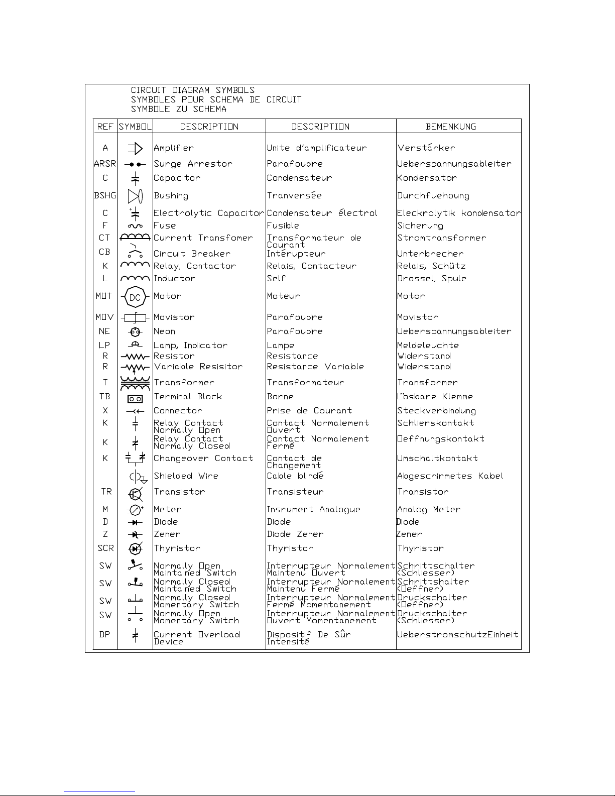
CIRCUIT DIAGRAM SYMBOLS 4
ELECTRICAL DRAWINGS 5
RECOMMENDED SPARE PARTS 6
PARTS ORDERING INFORMATION 7
RETURNED MATERIAL 8
Page 3

GENERAL SAFETY PRECAUTIONS
!
This equipment is capable of providing POTENTIALLY LETHAL VOLTAGES!
Improper operation or test practices may result in injury or death to the
operator or surrounding personnel.
The operation of High Voltage test equipment should only be performed by personnel
familiar with HIGH VOLTAGE testing and safety procedures. The operator of this
equipment must be aware of all hazards associated with High Voltage testing. The
operator is responsible for himself and others in close proximity of the testing area.
Some General Safety Practices for working with High Voltage Test Equipment have been
listed below for your reference.
• Become familiar with your instrument before performing an actual test
• Know your work area, check that all circuits are de-energized and locked out.
• Never work alone; always work with another qualified worker.
• Mark off entire work area with barriers and warning tape.
• Make all personnel aware of your testing activities.
• Be aware of dangerous conditions that may arise from energizing a test specimen.
• Never modify test equipment, modifications to equipment could introduce an
unknown hazard or hinder a designed-in safety feature.
• DO NOT operate damaged equipment. Remove power, and do not use the
equipment until safe operation can be verified by service-trained personnel.
Phenix Technologies, Inc. assumes no liability for unsafe or improper use of test equipment.
CAUTION
HIGH VOLTAGE
Page 4

1-1
INTRODUCTION
The Phenix Technologies VMS-2 Portable Power Supply is well equipped with
the various features listed on the specifications page to allow for the easy testing
of the operational voltage/current of electro-mechanical devices. The VMS-2
allows the user to dial in an output voltage or current to determine the operational
voltage or current levels of various electro-mechanical devices. Both the voltage
and current output levels can be simultaneously read and monitored with the
highly accurate, onboard meters. The VMS-2 is ideal for running small motors,
energizing power circuits, operating circuit breakers, powering substation relays
or for unregulated charging of substation batteries. The separate output
terminals for both AC and DC voltage provide convenient hookup configurations
depending on the type of component being tested.
Page 5

TECHNICAL SPECIFICATIONS
Model:
VMS-2 Portable Power Supply
Input:
220/240 Volts, 25 Amps, 60 Hz, Single Phase
Output:
0-240VAC; 25AAC MAX through Multilamm jacks (Will not reach 240VAC with the
220VAC input. Output will be 0-220VAC)
0-300VDC; 10ADC MAX through binding posts
Instrumentation:
AC Meters:
Digital Voltmeter, 3 ½ digit resolution
Digital Ammeter, 3 ½ digit resolution
DC Meters
Digital Voltmeter, 3 ½ digit resolution
Digital Ammeter, 3 ½ digit resolution
Features:
Main power circuit breaker with indicator lamp
Independent overloads for both outputs: AC – overload breaker; DC – output fuse
Output via Multilamm jacks (AC) and binding posts (DC)
Simultaneous digital readouts of both RMS Voltage and Current in both AC & DC
Two copies of instruction manual, parts list, and schematics
Size:
19”L x 18”W x 10”H; 65 lbs.
Scale: 0-300VAC. Accuracy: ± 0.4% FS ± 2 counts
Scale: 0-50AAC. Accuracy: ±0.15% FS ± 6 counts
Scale: 0-600VDC. Accuracy: ± 0.1% FS ± 1 count
Scale: 0-20ADC. Accuracy: ± 0.1% FS ± 1 count
1-2
Page 6

2-1
CONTROL AND METERING DESCRIPTION
(Key numbers refer to Figure 1)
1. Main Power Indicator Lamp. Lights when main power circuit breaker is energized and in
the ON position.
2. Main Power Circuit Breaker. Serves dual function as main switch and provides overload
protection for all circuits in test set.
3. AC Digital Voltmeter. Provides continuous display of AC output voltage in Volts.
4. AC Digital Ammeter. Provides continuous display of AC output current in Amps.
5. DC Digital Voltmeter. Provides continuous display of DC output voltage in Volts.
6. DC Digital Ammeter. Provides continuous display of DC output current in Amps.
7. AC Overload Circuit Breaker. Circuit Breaker will open once AC output exceeds 25A.
Close switch to reset breaker.
8. Main Variac Knob. Adjusts voltage and current output levels.
9. DC Overload Fuse. Fuse will blow when DC output exceeds 10A. Replace fuse via panel
fuse holder when needed.
10. AC/DC Output Selector Switch. Toggle to select either AC or DC output.
Page 7
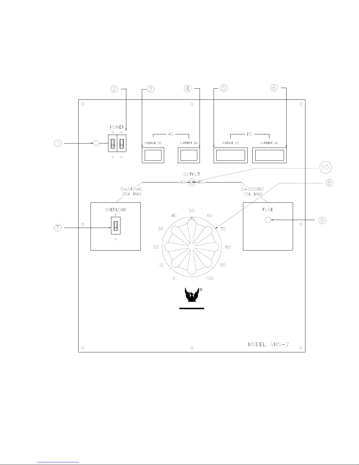
Figure 1: VMS-2 Front Panel
2-2
R
PHENIX
TECHNOLOGIES
Accident, Maryland, USA
Page 8

3-1
OPERATION AND CALIBRATION
OPERATION
Setup
1. Connect input power supply to on board terminal block on the rear of the panel with
240VAC or 220VAC, 25A source.
2. Ensure Main Variac knob is dialed to its zeroed out position before connecting output
terminals.
3. If either of the two Overloads is tripped, close the switch to reset the AC output breaker or
replace the DC output fuse.
4. Verify power is off and then connect the output supply via the Multilamm jacks or the
binding posts depending on whether AC or DC will be used and hook up the component to
be tested with the leads provided.
Operation
5. Turn on main circuit breaker switch to power on unit. Note indicator light comes on.
6. Slowly raise the output voltage by turning the Main Variac clockwise until the desired output
voltage or current is reached for the intended application or test.
7. Upon completion of testing, turn off main power by switching off the main breaker before
disconnecting the output leads from the test component.
8. For safety reasons, dial back the Main Variac knob to its zeroed out position before and
after each use.
Page 9

3-2
CALIBRATION
Your VMS-2 portable power supply itself does not require any calibration for normal operation.
The onboard digital Voltmeters and Ammeters will also hold their normally calibrated settings
during the lifetime of your VMS-2 for all normal indoor operations. In the rare case that any meter
needs calibration adjustments, the procedure for doing so should be performed by qualified
technical personnel such as the Phenix Technologies Service Department during a scheduled
service appointment.
MAINTENANCE
During the lifetime of your portable power supply, certain items will need replacement. Common
replacement parts are listed on page 7-1 under “Recommended Spare Parts.”
Page 10
4-1
Page 11

ELECTRICAL DIAGRAMS
Drawing Number
Description
1. 9907010 VMS-2 Electrical Schematic
5-1
Page 12

Page 13

RECOMMENDED SPARE PARTS
PHENIX
QTY.
4 1603601 AGC-1 Fuse
5 1603503 KTK-10 Fuse
1 1423265 Neon Lamp Green
2 N/A Output lead wires
1 1356212 Multilamm Plug Black
1 1356213 Multilamm Plug Red
4 1353042 Gator Clip – 20 Amp
2 1353041 Gator Clip Boot Black
2 1353040 Gator Clip Boot Red
2 1356312 MULTILAMM PLUG, 6mm, (600V/100A)
PART # DESCRIPTION
6-1
Page 14

7-1
PARTS ORDERING INFORMATION
Replacement parts are available from Phenix Technologies, Inc.
Changes to Phenix Technologies' products are sometimes made to accommodate improved
components as they become available, and to give you the benefit of the latest technical
improvements developed in our Engineering Department. It is, therefore, important when
ordering parts to include the serial number of the unit as well as the part number of the
replacement part. When your purchase order is received at our office, a representative of Phenix
Technologies will contact you to confirm the current price of the part being ordered. If a part you
order has been replaced with a new or improved part, an Applications Engineer will contact you
concerning any change in part number.
Your order for replacement parts should be sent to:
Replacement Parts Department
Phenix Technologies, Inc.
75 Speicher Drive
Accident, Maryland 21520
Page 15

8-1
RETURNED MATERIAL
If for any reason it should become necessary to return this equipment to the factory, the Service
Department of Phenix Technologies, Inc. must be given the following information:
Name Plate Information
Model Number
Serial Number
Reason for Return
Cause of Defect
If Phenix Technologies, Inc. deems return of the part appropriate, it will then issue an
"Authorization for Return".
If return is not deemed advisable, other inspection arrangements will be made.
NOTE: Material received at this plant without the proper authorization shall be held as
"Customer's Property" with no service until such time as the proper steps have been taken.
Your cooperation is requested in order to ensure prompt service.
 Loading...