

Page 1

JSH
FEB 17, 2012
PORTABLE HIGH CURRENT TEST SET
MODEL NUMBER HC-5
Version 5.0
Page 2

INTRODUCTION
The HC-5 is a portable high current test set built for field and shop use. Designed using the latest
technology, the HC-5 combines a variable high current output with appropriate controls and
instrumentation for testing thermal, magnetic, and solid-state motor overload relays, molded-case
circuit breakers, and ground fault trip devices. The HC-5 can be used in many other applications
requiring a high current source.
The HC-5 provides a short duration output of up to 5000 amps through a typical 500 ampere
molded-case circuit breaker when an instantaneous trip element must be tested. Sufficient current
is available for testing time delay characteristics of motor overload relays and molded-case circuit
breakers.
The unique auto-sensing feature makes the HC-5 easy to operate. Sensing leads, which operate
on either normally-open or normally-closed (non-energized) devices, are connected to the test
object auxiliary or non-energized contacts. The output current level can be easily pre-set. When
the output is initiated, the pre-set output current locks on and the timer starts. When the test set
senses a change in state of the test object auxiliary contacts (NO to NC or NC to NO), the current
shuts off and the timer stops. If set to sense current, unit will shut current off at approximately 9%
(4% of range at 5000 amps) of range switch setting of currentmeter when test object goes open.
For instantaneous trip tests, the memory feature of the currentmeter holds the peak current value
until reset by the operator.
Page 3

TABLE OF CONTENTS
Section Number
DANGER
TECHNICAL SPECIFICATIONS 1
WARNING 2
THEORY OF OPERATION 3
BASIC APPROACH TO TESTING 4
CALIBRATION 5
ELECTRICAL SCHEMATICS 6
PARTS LIST 7
PARTS ORDERING INFORMATION 8
RETURNED MATERIAL 9
Page 4
GENERAL SAFETY PRECAUTIONS
!
HIGH VOLTAGE
This equipment is capable of providing POTENTIALLY LETHAL VOLTAGES!
Improper operation or test practices may result in injury or death to the
operator or surrounding personnel.
The operation of High Voltage test equipment should only be performed by personnel
familiar with HIGH VOLTAGE testing and safety procedures. The operator of this
equipment must be aware of all hazards associated with High Voltage testing. The
operator is responsible for himself and others in close proximity of the testing area.
Some General Safety Practices for working with High Voltage Test Equipment have been
listed below for your reference.
• Become familiar with your instrument before performing an actual test
• Know your work area, check that all circuits are de-energized and locked out.
• Never work alone; always work with another qualified worker.
• Mark off entire work area with barriers and warning tape.
• Make all personnel aware of your testing activities.
• Be aware of dangerous conditions that may arise from energizing a test specimen.
• Never modify test equipment, modifications to equipment could introduce an
unknown hazard or hinder a designed-in safety feature.
• DO NOT operate damaged equipment. Remove power, and do not use the
equipment until safe operation can be verified by service-trained personnel.
CAUTION
Phenix Technologies, Inc. assumes no liability for unsafe or improper use of test
equipment.
Page 5

1-1
HC-5 TECHNICAL SPECIFICATIONS
INPUT: 220-240 Volts, 50 Amps - Delay
50 Hz or 60 Hz (must be preset)
OUTPUT: 0-15 Volts, 0-333 Amps
0-10 Volts, 0-500 Amps
0-5 Volts, 0-1000 Amps
OVERLOAD: Short duration overloads are possible on each tap. The test set is capable of up to
5000+ amps, depending on the impedance of the test circuit.
DUTY CYCLE: Continuous at 100%
5 minutes ON/15 minutes OFF at 200%
1 minute ON/10 minutes OFF at 300%
10 seconds ON/5 minutes OFF at 400%
3 seconds ON/5 minutes OFF at 500%
INSTRUMENTATION: Currentmeter: 4 1/2 digit LCD
Ranges: 0-1.9999/19.999/199.99/5000+ amperes
Accuracy: +/- .5% F.S. to 2000 Amps, ± 1% F.S. 2000-5000 Amps
Timer: 6 digit LCD, in cycles or seconds
Ranges: 0-999999 cycles or 0-9999.99 seconds
Accuracy: +/- 0.1% reading
DIMENSIONS: 22 1/4" W x 22 1/4" D x 46" H; (266 lbs. with cables)
(565 mm W x 565 mm D x 1168 mm H; 121 kg)
OUTPUT LEADS: 8 ft. sense leads
2 ft. high current leads (Parallel 4/0)
6 ft. low current leads (10 Ga)
4 ft medium current leads (4 Ga)
Page 6

2-1
WARNING
1. For safe operation, it is important that the unit be plugged into a properly grounded receptacle.
2. This unit is not designed for use in energized circuits.
3. Due to leakage current within the solid-state circuitry, it is strongly recommended to turn control
power off when changing the output leads.
4. Never connect sense jacks to energized contacts or terminals being injected by test unit.
Page 7

3-1
THEORY OF OPERATION
The following is a listing of the controls, switches, and lamps on the control panels and a description
of their functions.
INPUT Input cable plugs in here to provide input power.
MAIN POWER This controls the input power to the control and the power section, and
provides power circuit protection.
OUTPUT Protect the variable transformers.
F1, F2 Protects the control circuitry and power supplies.
HC ON When pressed, this allows current to flow from the unit (provided that the
output is shorted as through a closed breaker). If this output current
exceeds approximately 9% (4% of 5000A range) of the selected output
current range, the output will be maintained when the switch is released.
Also, the TIMER will begin to run at this point.
HC OFF When this is pressed, the output current will cease to flow from the unit.
JOG This switch is used when it is desired to preset output current to a specific
level. When pressed, the output current will begin to flow as it would when
HC ON is pressed. The difference is that the TIMER will not begin running
in this mode, and the output current will cease to flow when the switch is
released, regardless of its magnitude.
CURRENT CONTROL Controls current level from minimum to maximum of output tap when HC
ON or JOG is activated. Use with JOG to preset current level through test
object.
TRIP/RESET This switch serves several purposes.
1) When in CONTACTS mode, the lamp will illuminate to indicate that the
non-energized contacts of the test specimen connected to the SENSE
INPUTS have changed states.
2) When in CURRENT mode, the lamp will illuminate to indicate that the
output current has dropped below the 9% level (4% of 5000A range).
3) When pressed, the TIMER will be reset to zero.
4) When the CURRENTMETER MEM/CONT is set to the MEM mode,
pressing reset will release currentmeter from its highest registered
reading. If the output current is not at zero, the present output reading
will be maintained until either the output level increases, or the reset is
pressed again.
5) When illuminated, it must be pressed to reset controls for further
operation.
Page 8

3-2
THEORY OF OPERATION
SENSE SWITCH This can be set to CONTACTS or CURRENT mode. When placed in
CONTACTS mode, the unit will react to a change in condition of the
SENSE INPUTS (Normally Open to Normally Closed, or Normally Closed to
Normally Open). Upon a change in condition, the TIMER will stop running
and the output current will cease to flow. The TRIP lamp will illuminate as
an indication to the operator of a change in condition.
In CONTACTS mode, sense leads must be properly connected to non-
energized contacts operated by the test specimen or the timer will not
shut off when the test specimen goes open. If the sense leads are not
used, the sense switch must be in CURRENT position for proper
functioning.
When the SENSE switch is set to the CURRENT mode, the unit will react
to the output current dropping below approximately 9% (4% of 5000A
range) of the level of the selected current range.
SENSE INPUTS These are connected to an auxiliary set of contacts (non-energized)
regardless if they are normally open or closed. When RESET is pressed,
the unit will remember its state. If the state changes, the unit will react to
this change if the SENSE switch is set to CONTACTS.
Please do not attempt to connect these to the same set of contacts
which you intend to energize, or energized auxiliary contacts. This
may cause damage to the unit.
CURRENTMETER This displays the RMS value of the output current level of the unit. There
are four ranges available:
2 Amp 1.9999
20 Amp 19.999
200 Amp 199.99
5000 Amp 5000+
WARNING: Please note that there is no correlation between the
currentmeter range switch setting and the rating of the taps.
MEM/CONT When set to the CONT (continuous) mode, the meter will continuously
update to display the output current level. When placed in the MEM
(memory) mode, the meter will retain the highest output current level
achieved. If the level again exceeds this value, the meter will be updated.
If you are below the highest level, pressing RESET will update the meter to
the present level of output.
Please note that the MEM mode of operation will only maintain the reading
for a short time before the reading starts to decay.
Page 9

THEORY OF OPERATION
TIMER The timer will begin counting when HC ON is pressed and the current
surpasses the 9% or 4% level. The timer will stop when the current drops
below the 9% or 4% level in the SENSE CURRENT mode. When in the
SENSE CONTACTS mode, the timer will stop when a change in the
SENSE INPUTS is detected.
The timer can be set to read CYCLES or SECONDS.
3-3
Page 10

4-1
BASIC APPROACH TO TESTING
The HC-5 is basically a continuously variable high current source, the magnitudes of which are
dependent on the output tap which is selected. Please refer to the Technical Data and
Specifications for the voltage and current ratings of the taps.
The output current is controlled by use of the CURRENT CONTROL knob on the control panel. By
turning the knob in the clockwise direction, the current is raised. By turning the knob in the counterclockwise direction the output magnitude is decreased.
The RMS value of the output current is displayed on the CURRENTMETER. If the MEM/CONT
switch is in the CONT (for CONTinuous), the meter displays the real-time value of the output. If the
MEM/CONT switch is in the MEM (for MEMory), the highest value of the output current is displayed.
When a breaker is to be tested, the operator may select the SENSE CONTACTS mode or the
SENSE CURRENT mode of operation. If an auxiliary set of non-energized contacts are available,
the SENSE CONTACTS mode may be selected. By pressing JOG or RESET the state of the
contacts (be it normally open or normally closed) are remembered by the unit. The operator may
then preset the output current to the desired level by use of the JOG switch. When this is done, by
pressing HC ON (and assuming that the current level exceeds approximately 9% of the
CURRENTMETER range selected; (4% on 5000A range) the current will continue flowing after the
switch is released and the TIMER will begin to run. When the contacts connected to the SENSE
INPUTS change state, the TIMER will stop running and the output current will cease to flow. The
TRIP lamp will illuminate as an indication to the operator. If the MEM/CONT switch is in the MEM
mode, the highest output current achieved will be displayed on the CURRENTMETER. The
operator should note this level before the readings begin to decay. Pressing RESET will zero the
TIMER and CURRENTMETER readings, and prepare the unit for operation again.
When the SENSE switch is set to the CURRENT mode, the SENSE INPUTS are not used. This
position was meant mainly for single pole breakers in which the SENSE INPUTS cannot be used.
In this mode initiation of the test is the same as in SENSE CONTACTS mode. The difference is the
completion of the test. When the output current falls below 9% or 4% of range (as when the
contacts of the breaker open) the TIMER stops running and the output current turns off. The TRIP
lamp illuminates as an indication to the operator.
Page 11

5-1
CALIBRATION
TIMER The timer is run from a precision programmable oscillator and should never
require calibration.
CURRENTMETER The calibration of the currentmeter should be checked on a yearly basis.
To do this, place the MEM/CONT switch in the CONT position. Place the
range switch in the 2 AMP range. With nothing connected to the output
and the CURRENT CONTROL knob in its fully counter-clockwise position,
adjust R10 until the CURRENTMETER reads zero. With appropriate test
equipment (RMS) raise the output current to 80% of each range and adjust
the corresponding calibration potentiometer to agree with your standard.
2 Amp R84
20 Amp R85
200 Amp R69
5000 Amp R73
Page 12

ELECTRICAL SCHEMATICS
Drawing Number Description
1. 9304535 Sheet 1 HC-5 Electrical Schematic
6-1
Page 13
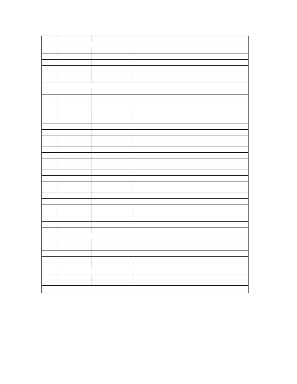
Qty Part Number Item Description
1 1153309 Cable, Input Connector, Connector Body
1 1153308 Panel, Input Connector, Flanged Inlet
2 1603602
2 1603920 F1, F2 Fuse Holder
1 1601352 CB1 Main Power Circuit Breaker – 50 Amp
1 1601327 CB2 Output Circuit Breaker – 25 Amp
2 1351100 JACKS-SENSE Binding Post, Black
1 1892209 CT1 Current Transformer, 2000:1
4 1420143
1 1422151 HC OFF Lens, Green
2 1422150 HC ON, JOG Lens, Red
1 1422148 RESET Lens, Blue
1 1422152 RESET Lens, Yellow
1 1506405 M1 Current Meter, 4 ½ Digit
3 1606110 MOV1-3 Movistor, V275LA40A
1 1590110 P.S. 5V Power Supply, 5 Volt
2 1741990 R200,201 Resistor, 1kOhm, 10W
1 31136100 PCB1361 PCB1361: HC CNTRLS AND PWR ASSY
2 1151955 J1,J2 JUMP-JAX ROHS
1 31122306 PCB1223 PCB1223 ASSY FOR HC-5
1 1721700 R206 Resistor, 910 Ohm, .5W, 1%
1 1722091 R207 Resistor, 3.65 kOhm, .5W, 1%
4 1860120 SW1,3,4,5 Switch, HC ON, OFF, JOG, RESET
3 1865010 SW2,8,9 Mem/Cont, Cycles/Seconds, Current/Contacts
1 1355310 SW6 Knob, Current Range SW
1 1891938 T1 Current Control Wheel
1 1863042 SW6 Switch, Current Range
1 1505420 Timer Timer, Red Lion, Sub Cub D, SCUB-D2-00/A
1 1505421 Timer Bezel Kit, HWK-60-000/D
1 1700390 SSR1 Relay, Solid State
2 1890239 T1 Transformer, Variable
1 2350125 Fan 1 Cooling Fan
1 1077300 Cord Set, Fan
1 38602152 T2 IA1-2152, Output Transformer
1 2371045
2 2109500 Bumpers, Cover
HC-5 PARTS LIST
INPUT PANEL
*F1, F2
*HC ON, HC
OFF, JOG,
RESET
REGULATOR/OUTPUT
MISCELLANEOUS/MECHANICAL
*
*INDICATES RECOMMENDED SPARE PARTS TO KEEP ON HAND
Fuse, 1.5A, 250V, Fast Acting Fuse
CONTROLS
Lamp, 6.3V
Latch, Cover
7-1
Page 14

8-1
PARTS ORDERING INFORMATION
Replacement parts are available from Phenix Technologies, Inc.
Changes to Phenix Technologies' products are sometimes made to accommodate improved
components as they become available, and to give you the benefit of the latest technical
improvements developed in our Engineering Department. It is, therefore, important when ordering
parts to include the serial number of the unit as well as the part number of the replacement part.
When your purchase order is received at our office, a representative of Phenix Technologies will
contact you to confirm the current price of the part being ordered. If a part you order has been
replaced with a new or improved part, an Applications Engineer will contact you concerning any
change in part number.
Your order for replacement parts should be sent to:
Replacement Parts Department
Phenix Technologies, Inc.
75 Speicher Drive
Accident, Maryland 21520
Page 15

9-1
RETURNED MATERIAL
If for any reason it should become necessary to return this equipment to the factory, the Service
Department of Phenix Technologies, Inc. must be given the following information:
Name Plate Information
Model Number
Serial Number
Reason for Return
Cause of Defect
If Phenix Technologies, Inc. deems return of the part appropriate, it will then issue an "Authorization
for Return".
If return is not deemed advisable, other inspection arrangements will be made.
NOTE: Material received at this plant without the proper authorization shall be held as
"Customer's Property" with no service until such time as the proper steps have been taken.
Your cooperation is requested in order to ensure prompt service.
 Loading...