

Page 1

MXC-4K862-HDTL-KIT
8x6+2 HDBaseT™ 18Gb 8X8 Matrix Kit
User Manual
Series
VER 1.0_ 06062019 MXC-4K862-HDTL-KIT User Manual
Page 2

MXC-4K862-HDTL-KIT USER MANUAL
Thank you for purchasing this incredible
product.
For best performance and safety, please read
these instructions carefully before connecting and
operating this product.
Surge protection device recommended
This product contains sensitive electrical components that may be damaged by electrical spikes,
power surges, electro static discharge (ESD),
lightning strikes or transients. The use of surge
protection systems is highly recommended in order
to protect and extend the life of your equipment.
Safety and Performance Notice
The transmission distances of HDMI over UTP Cat
cables are measured using TE CONNECTIVITY
1427071-6
EIA TIA-568-B termination (T568B) of cables is
essential for optimal performance.
Do not run the HDBaseT™ / Cat5e/6/6a cabling in
close parallel proximity or close to mains power
cables. This will minimise interference of the unshielded twisted pairs in the CAT5e/6 cable, which can
cause problems with the signal transmission.
Only use the power supply supplied with the unit,
or a PhD Solutions supplied replacement.
Do not disassemble any of the equipment. This will
void the manufacturer’s warranty.
Table of contents
Introduction..............................................................
Features..................................................................
Package Contents...................................................
Optional Accessories...............................................
Specifications..........................................................
Colour Space Conversion (CSC)............................
Operations Controls & Functions............................
HDBaseT™ Display Receiver.................................
Infrared (IR) Distribution..........................................
Master Remote Control...........................................
Web GUI Setup Guide.............................................
EDID Management..................................................
Matrix Control Protocols & Drivers..........................
Cable Termination & Best Practices........................
Application Diagram................................................
Troubleshooting.......................................................
Product Warrantee..................................................
1
2
3
4
5
6
6
8
9
12
13
17
18
18
20
21
22
2
www.phdsolutions.co
Page 3

MXC-4K862-HDTL-KIT USER MANUAL
1.Introduction
The ECO 8x8 HDBaseT™ Matrix is built with the latest features, at economic price points and is
tailored for the custom installer. It supports HDMI2.0 4K60Hz 4:4:4 HDCP2.2 HDR-18Gbps up to
40m and 1080P up to 70m.Embedded with CSC visually lossless compression technology it
delivers HDMI, Bi-directional IR, and PoC (PoE) over a single CAT cable. The Matrix also prov-
ides 6x HDBaseT™ outputs and 2x independent HDMI output, audio de-embedding configurable
to one of the outputs and advanced EDID management. The Matrix KIT is supplied with 6 x
EXC-4KP70-HDTL-RX HDBaseT™ display receivers. Sources can be selected from the front
panel buttons, IR remote control, RS-232, LAN or Web GUI. Control drivers are available for 3rd
Party control systems (ELAN, Control4, RTI, Crestron etc).
2.Features
• HDBaseT™ distribution of video and audio over a single CAT cable
• Colour Space Conversion (CSC) visually lossless compression technology supports: HDMI2.0
4K604:4:4 HDR 8bit/10bit 18Gbps
• Extends 1080P60Hz 48 bit, 1080P120Hz 24 Bit , 4K60Hz 4:2:0 and 4K60Hz 4:4:4 UHD HDR,
video up to 40m
• Extends HDMI 1080P60Hz 36bit video up to 70m
• Features 8x HDMI 2.0 inputs which can be independently routed to 6x HDBaseT™ outputs
and 2x independent HDMI 2.0 outputs
• Configurable analogue stereo audio or SPDIF optical audio de-embedding to follow one of
eight HD outputs
• Supports most digital HDMI audio formats including Dolby TrueHD, Atmos; DTS-HD Master
Audio and DTS:X transmissions
• Web interface GUI for control and configuration
• Supports bi-directional IR on all HDBaseT outputs
• Supplied with 5v IR(RX) receivers and IR (TX) emitters
• Supplied with 6 x EXC-4KP70-HDTL-RX HDBaseT™ display receivers
• Control via front panel, IR, RS-232, TCP/IP and web-GUI
• Supports PoC (Power over HDBaseT™) to power compatible HDBaseT™ receivers
• 3rd Party drivers available for most major 3rd party control brands
• Advanced EDID management
• HDCP2.2 and HDCP 1.4 compliant
of the matrix
www.phdsolutions.co
3
Page 4

MXC-4K862-HDTL-KIT USER MANUAL
3.Package Contents
• 1 x MXC-4K862-HDTL Matrix
• 1 x RS232 cable
• 1 x IEC Power cable
• 1 x IR master remote control
• 1 x User manual
• 2 x 19” 1U Rack mounting ears for the matrix
• 6 x EXC-4KP70-HDTL-RX HDBaseT™ Display Receivers
• 7 x Phoenix terminals (male)
• 12 x Surface mounting brackets for EXC-4KP70-HDTL-RX HDBaseT™ Receivers
• 15 x ECO-IR-TX 5V IR (TX) emitters
• 16 x ECO-IR-RX 5V IR (RX) receivers
4.Optional accessories
These optional accessories are not included with this Matrix KIT and can be purchased separately
ECO-REM8 8-button basic IR room remote controls
PHD-OPTOCABLE-E: Optically isolated IR control cable, 3.5mm Mono to 3.5mm Stereo jack,
for IR passthrough from third party control solutions to PhD Solutions ECO matrices and extenders.
Compatible with 12v IR third party products. Note: Cable is directional -Mono end plugs into IR
output of the control system -stereo end plugs into the IR input of the matrix or extender.
4
www.phdsolutions.co
Page 5
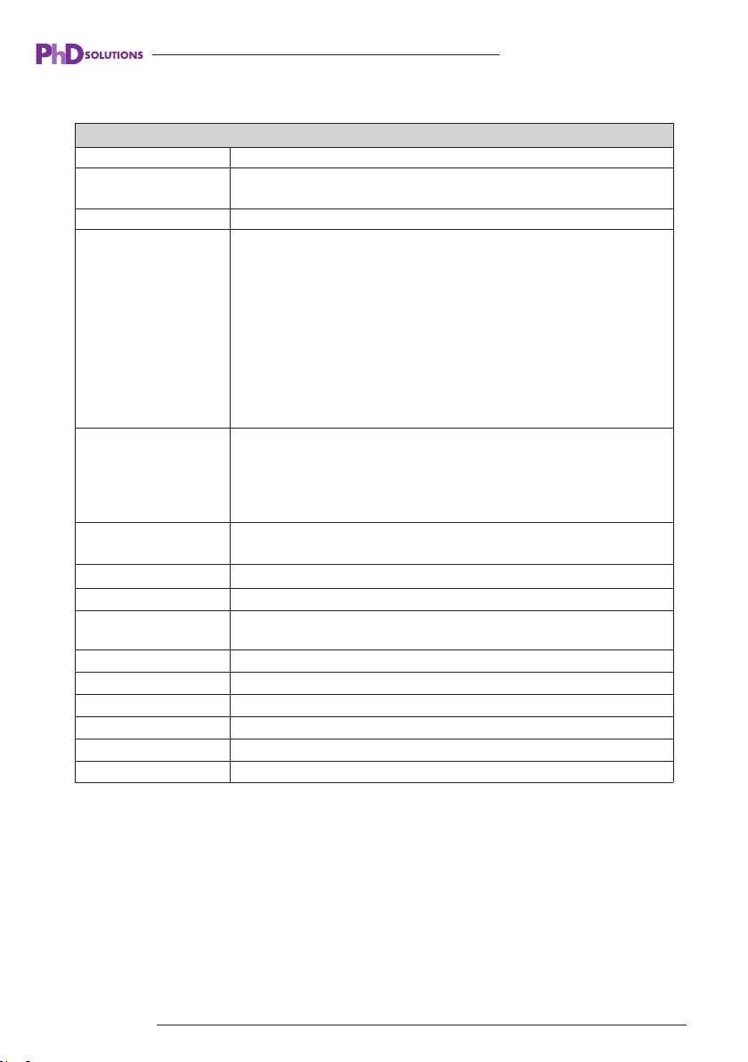
5.Specifications
Technical
Video Bandwidth 600MHz[18Gbps]
Video Resolution
HDBASET Class B
Matrix
Receiver
ESD Protection
Chassis Material Metal
Silkscreen Color Black
Dimensions
Weight MATRIX CHASSIS : 3kg, DISPLAY RECEIVER: 206g
Power Supply (Internal) 100~240V AC 50/60Hz- IEC
Power Consumption
Operating Temperature 0°C ~ 40°C / 32°F ~ 104°F
Storage Temperature -20°C ~ 60°C / -4°F ~ 140°F
Relative Humidity 20~90% RH (non-condensing)
480i, 576i, 480p, 576p, 720p, 1080i, 1080p24/30/
50/60, 4Kx2K@30, 4Kx2K@60 (4:4:4)
Input Ports:
8×HDMI Type A [19-pin female]
9×IR input [3.5mm Stereo Mini-jack]
1×RS-232 [Phoenix connector]
1×LAN [RJ45 connector]
Output Ports:
2×HDMI Type A [19-pin female]
6×HDBaseT CLASS B Out [RJ45]
9×IR output [3.5mm Stereo Mini-jack]
1×Optical audio [S/PDIF]
1×Stereo audio [3.5mm Stereo Mini-jack]
Input ports: 1×HDBaseT CLASS B In [RJ45]
1×IR In [3.5mm Stereo Mini-jack]
Output ports: 1×HDMI Type A [19-pin female]
1×IR Out [3.5mm Stereo Mini-jack]
1×RS-232 [Phoenix connector]
Human body model —— ±8kV (Air-gap discharge),
±4kV (Contact discharge)
MATRIX CHASSIS: 440mm(W)*320mm(D)*44.5mm(H)
DISPLAY RECEIVER: 115mm(W)*65mm(D)*17mm(H)
74W
MXC-4K862-HDTL-KIT USER MANUAL
NOTE: Specifications are subject to change without notice.
www.phdsolutions.co
5
Page 6
MXC-4K862-HDTL-KIT USER MANUAL
6.Colour Space Conversion (CSC) Technology over
HDBaseT™
HDBaseT™ technology is limited to the maximum bandwidth of CAT cable at 10.2 Gbps, it does
not have enough bandwidth to support the 18Gbps required for 4K UHD resolutions of 4K 60Hz
4:4:4 or 4K60Hz 4:2:2 with HDR 8/10bit colour space. With new sources and displays supporting
these high bandwidth resolutions there is now a requirement to integrate video resolutions with
data speeds up to 18 Gbps over distance to multiple locations. We have implemented CSC
(Colour Space Conversion) technology into our latest products to ensure 4K HDR signals can
now be supported over the 10.2 Gbps infrastructure of HDBaseT™.
Colour Space Conversion reduces the data rate of the HDMI signal by converting the colour space
(or Wide Colour Gamut) from 4:4:4 or 4:2:2 to a lower format. Within Colour Space Conversion
technology, the native resolution and frame rate remain constant from end to end. The only part
of the signal that is converted during transmission is the colour gamut variations.
* CSC products do not support HDR10+ or Dolby Vision due to the way these specific creations
of HDR are encoded. These codecs transmit repeated metadata packets throughout the trans-
mission of any media making it impossible at this stage to convert in the same way using CSC
technology.
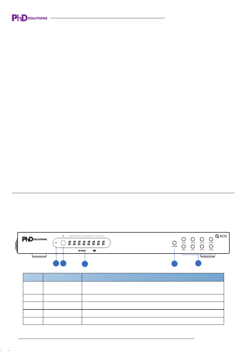
7.Operations Controls and Functions
Front Panel
MXC-4K862-HDTL
Number Function descriptionName
LED power
1
indicator
2 IR receive window Receives IR codes from IR remote controls to control the matrix.
3 Display Shows the display output & source Input number.
4 POWER button Power on/off button.
5 OUTPUT button A/B/C/D/E/F/G/H output source button.
1
2
4K60 HDR HDCP
6 www.phdsolutions.co
2.2
3
3
4
When the Matrix is in standby mode the LED shows red. The LED
shows blue input numbers when matrix is working normally.
4
5
Page 7
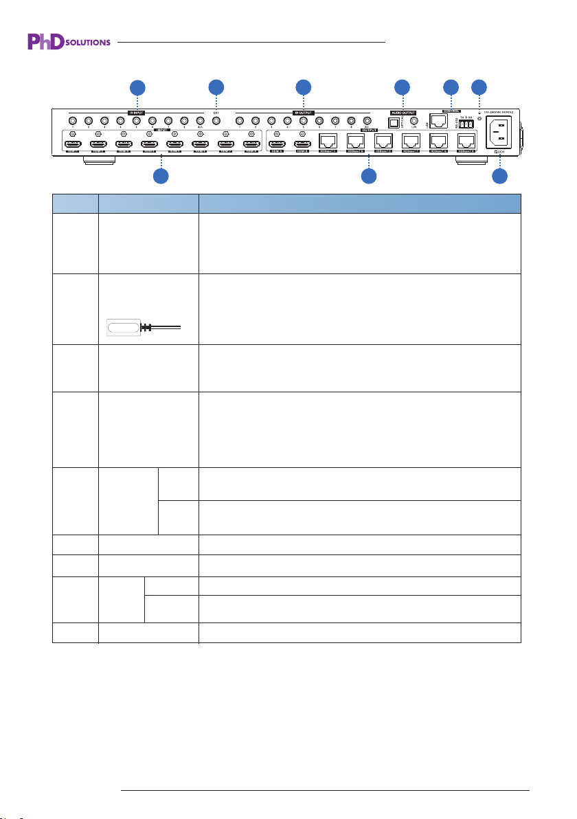
Rear Panel
MXC-4K862-HDTL-KIT USER MANUAL
1
2
3
4
5
6
7
3
LAN
RS-232
4
IR input ports-1&2 have no function, IR input ports 3-8 sends 5V
IR out to C,D,E,F,G & H corresponding HDBaseT™ Zones. PHDOPTOCABLE-E will be required when sending IR into these ports
from a 3rd party control system.
If the front IR sensor of unit is obstructed or the unit is installed in
a closed area out of infrared line of sight, the 5v IR (RX) receiver
included can be inserted into the IR EXT port at the rear of the
matrix to extend the IR sensor range and enable local IR control
of the matrix
IR output ports-connect the supplied 5V IR(TX) emitter cables
here and place on the corresponding HDMI source1-8 these are
discrete ports
De-embedded audio output ports. By default, it follows HDMI
output A audio. The de-embedded audio output is configurable in
the matrix web interface to follow any one of the 8 HD outputs.
NOTE: Optical port can support PCM and compressed audio
formats, but L/R analogue audio port only supports PCM audio.
TCP/IP (RJ45) – Connect to LAN for TCP/IP control of Matrix
and Web GUI.
Connect to a PC or control system for RS232 serial control via
the Phoenix terminal to transmit & receive commands.
HDBaseT™ outputs C/D/E/F/G/H. Connect to the supplied PoC HDBaseT™
display receiver over cat cable.
Number Function descriptionName
1 IR INPUT
2 IR EXT PORT
3 IR OUTPUT
4 Audio OUTPUT
5 CONTROL
6 GND Connect to earth the chassis to ground.
7 HDMI 2.0 INPUTS HDMI 2.0 Inputs 1-8 Connects HDMI sources to the matrix
OUTPUT
8
9 AC POWER INPUT Connect to AC power with IEC AC power cable.
HDMI 2.0 Connect to HDMI display devices, such as TVs or Monitors.
HDBaseT™
98
www.phdsolutions.co 7
Page 8
MXC-4K862-HDTL-KIT USER MANUAL
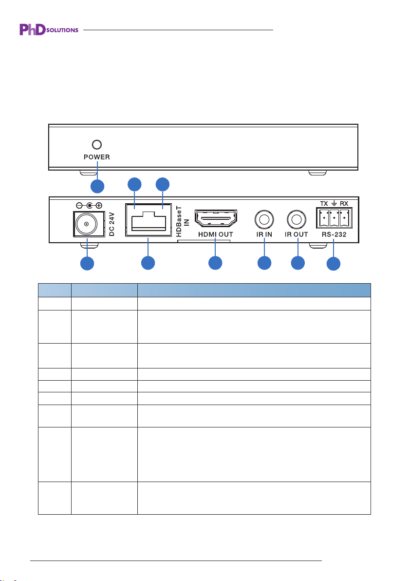
8.HDBaseT™ Display Receiver
The Matrix is supplied with 6x EXC-4KP70-HDTL-RX HDBaseT™ display receivers
The EXC-4KP70-HDTL-RX Receiver is a Class B HDBaseT™ receiver with 2-way IR pass-through.
The receiver supports display distances up to 70
at the input).
m @ 1080P and 40m 4K (4K60 4:4:4 / 18Gbps
EXC-4KP70-HDTL-RX
1
2
Number Function descriptionName
1 This LED illuminates when the device is connected with power supply.POWER
2 DC 24V
3 HDBaseT™ IN
4 HDMI OUT HDMI output port. Connect to the display with an HDMI cable.
5 IR IN IR Receiver input. Connect the 5V IR Rx cable here.
6 IR OUT IR transmitter output. Connect the 5V IR TX blaster cable here.
7 RS-232
Connection Signal
8
Indicator Lamp
Data Signal
9
Indicator Lamp
8 9
3 4
3
4
No connection is required
(The matrix will power the receiver balun from the HDbaseT IN
port over PoC from the matrix.)
Standard HDBaseT™ signal input port. Connect to Matrix
HDBaseT™ output with a terminated UTP CAT cable.
Connect to a PC or control system with phoenix jack for transm-
ission of RS-232 serial commands.
※Illuminate: The Transmitter and Receiver are in good connection
status.
※Flashing: The Transmitter and Receiver are in poor connection
status.
※Dark: The Transmitter and Receiver are not connected.
※Illuminate: The HDMI signal with HDCP.
※Flashing: The HDMI signal without HDCP.
※Dark: No HDMI signal.
5 6
7
8 www.phdsolutions.co
Page 9
MXC-4K862-HDTL-KIT USER MANUAL
9.Infrared (IR) Distribution
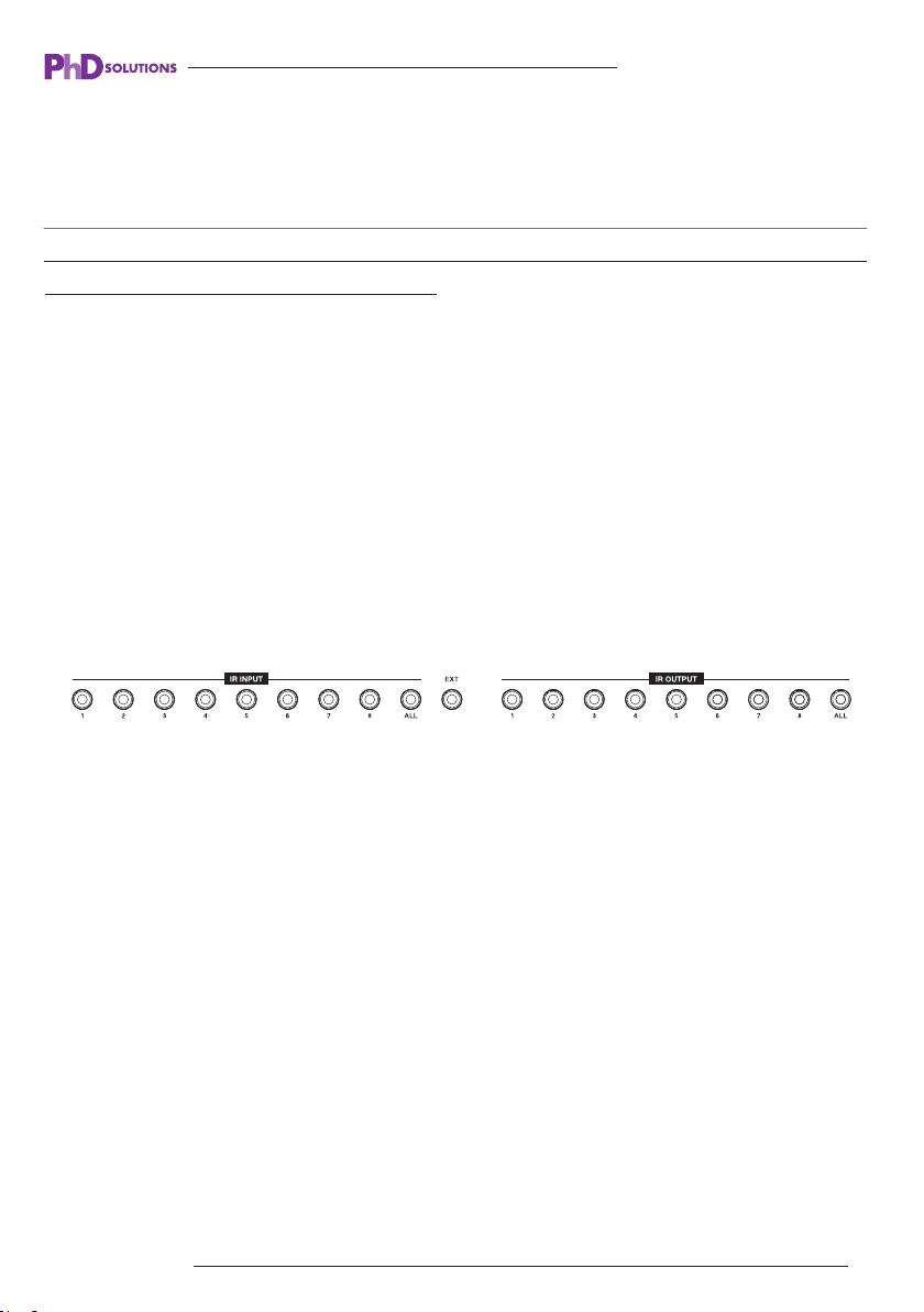
The matrix includes multiple options for control and routing of IR signals.
IMPORTANT: PhD Solutions Infrared matrices and extenders are all 5v and are NOT compatible
with alternative manufacturers Infrared solutions. Please use the supplied IR (TX) Emitters/blasters
& IR (RX) Receivers supplied with the matrix.
The matrix is a switcher and extender of multiple HDMI signals to multiple HDMI receivers located
remotely, it also passes IR control signals through the IR call-back system to the matrix and HDMI
sources for independent control of connected outputs from input locations.
Two-way IR Call-back between matrix, Sources and displays from multiple locations.
A key feature of the matrix is discrete IR control of the matrix, sources and displays from different
locations. Inputs at the matrix end can be controlled at a display location and displays can be
controlled at the matrix location. This is accomplished by placing a series of IR (TX) Emitters/
blasters on devices to control and IR (RX) Receivers at all the locations you wish to control from.
The IR signal travels both ways via the single Cat5e/6/7 cable connected to the display receiver
balun.
IR control from display location.
Insert the 3.5mm IR (TX) emitter/blaster cables into IR OUTPUT ports at the rear of the matrix.
Place the IR (TX) emitter/blaster over the IR window of the source device you wish to control.
At the display connect the HDBaseT™ display receiver extender balun to the matrix’s HDBaseT™
C,D,E,F,G&H ports with a suitable CAT cable. Insert the 3.5mm IR (RX) receiver cable into the
IR IN port of HDBT receiver balun.
www.phdsolutions.co
9
Page 10

MXC-4K862-HDTL-KIT USER MANUAL
When the user controls the matrix from the display location via remote control, the matrix IR
OUTPUT follows the HDMI video input source. This mean that discrete IR is passed from the IR
(RX) receiver connected to the HDBaseT™ display receiver, down the cat cable to the matrix
and outputted through the IR output ports which are matched to the corresponding video source
selected.
The ALL output port passes all IR commands received by any of the IR (RX) receivers connected
to HDBaseT™ display receiver baluns.
Please note that the local HDMI A & B ports of the matrix have no IR control. IR INPUT 1 &
2 also has no function.
Control for HDMI A/B output will need to be done at the matrix via one of 3 methods:
① Local control at the Matrix: Point the remote control at the front panel of the matrix
② Extend IR control: Insert the 3.5mm IR (RX) receiver cable into the IR EXT port of the Matrix
③ From a 3rd party Control System: via IP, RS232 or IR
Note: Source control will need to be done directly from the sources, by a 3rd party control system
or IR routing system
IR control from a 3rd party control system
IMPORTANT: PhD Solutions Infrared matrices and extenders are all 5v and are NOT compatible
with most alternative manufacturers Infrared solutions. When using third party 12v IR control
solutions please use the optional PHD-OPTOCABLE-E Opto-isolated cable for IR conversion,
these are available as an optional accessory from your dealer.
From the control system’s IR output port plug in the 3.5mm Mono end of the Opto-isolated cable
(Part no. Phd- OPTOCABLE-E) Insert the 3.5mm stereo end into the required IR INPUT port at
the rear of the matrix.
At the display connect the HDBaseT™ display receiver extender balun to the matrix HDBaseT™
C,D,E,F,G&H ports with a suitable CAT cable. Insert the 3.5mm IR (TX) emitter/blaster cables into
the IR OUT port of HDBaseT™ display receiver. Place the IR (TX) emitter/blaster over the IR window
of the display you wish to control.
The matrix IR INPUT port passes through IR to the HDMI video output display. This means that
discrete IR is passed from the 3rd party control system to the matrix IR INPUT Port, down the cat
cable to the HDBaseT™ display receiver and out the IR(TX) emitter/blaster to the display.
10
www.phdsolutions.co
Page 11

MXC-4K862-HDTL-KIT USER MANUAL
IR input routing will work as follows: IR Input 3 corresponds to HDBaseT™ output Port C, IR
Input 4 corresponds to HDBaseT™ output Port D, IR Input 5 corresponds to HDBaseT™ output
Port E. IR Input 6 corresponds to HDBaseT™ output Port F, IR Input 7 corresponds to HDBaseT™
output Port G. IR Input 8 corresponds to HDBaseT™ output Port H.
PLEASE NOTE: IR Input 1&2 has no function as HDMI output Port A& B are not a CAT extension
ports.
The IR EXT input will receive IR matrix switching commands.
www.phdsolutions.co 11
Page 12
A
B
C
D
DISPLAY
1
A
B
C
D
SOURCE
DISPLAY
1 2 3 4
5 6 7 8
A B C
D
E F G
H
ALL
1
2
2
3
4
MXC-4K862-HDTL-KIT USER MANUAL
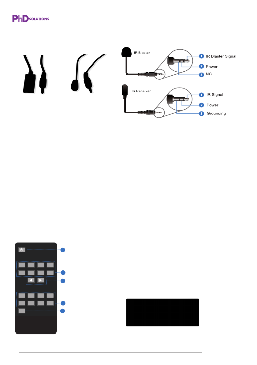
IR Pin-outs
IR (RX) Receiver and IR (TX) Emitter/Blaster
IR RECEIVER IR BLASTER
Each PhD ECO Matrix KIT is supplied with all necessary IR hardware required and includes:
Contextual IR
The Matrix receives CONTEXTUAL infrared (IR) commands from display receivers, determining
which zone output the IR command originated from. Contextual IR allows for the use of simplified
remotes with less buttons compared the Master Remote supplied with the matrix, these are the
optional ECO-REM8 room remotes. Contextual IR allows you to roam between rooms with the
same room remote, and the matrix knows exactly which zone you are controlling from.
10.Master Remote Control
① POWER BUTTON to toggle on/off standby power of the matrix.
② INPUT -OUTPUT SELECT keys: First Select the DISPLAY
OUTPUT A,B,C,D,E,F,G,H next select the required SOURCE
INPUT 1,2,3 4,5,6,7,8
③ Use the left or right arrow keys to select next or previous source
12 www.phdsolutions.co
inputs.
④ Press the ALL Button then Select a Source number. This will
disable the left and right source arrow keys.
Note: optional ECO-REM8 basic 8 button room IR remotes are
available for purchase, these have no power on/off function
Page 13
11. Web GUI Setup Guide
MXC-4K862-HDTL-KIT USER MANUAL
The Matrix can be controlled via the built in W
matrix into any device (smartphone, tablet, PC or Mac) on the local network with a web browser.
The default static IP address of the matrix is 192.168.1.100.
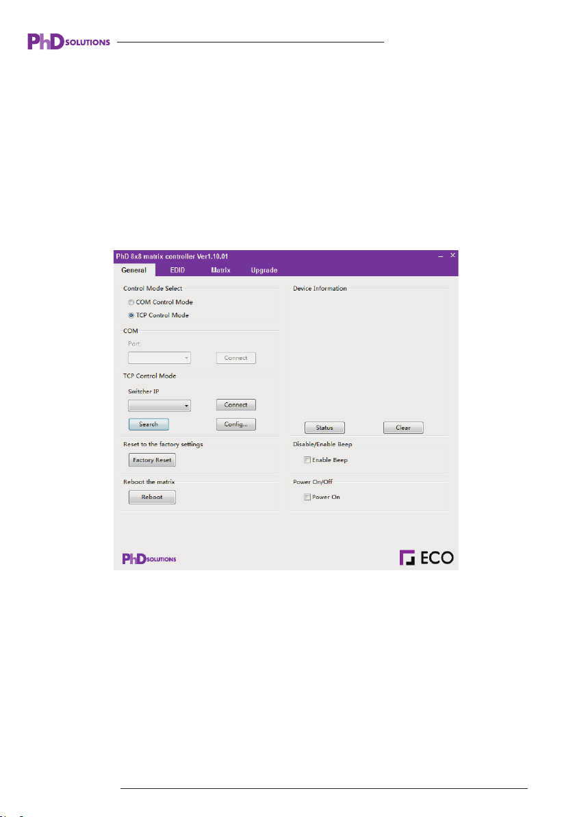
You can also find the matrix’s IP address via Eco Matrix PC Controller software. Software can be
downloaded from the PhD solutions website: www.phdsolutions.co Launch the Eco Matrix PC
Controller software utility :
eb GUI interface, by typing in the IP address of the
Then select the “TCP Control Mode” port, click the “Search” button. You will the see the current
IP address of the matrix. Put the Matrix’s IP address in to your web browser to enter the matrix’s
local Web GUI page.
www.phdsolutions.co
13
Page 14
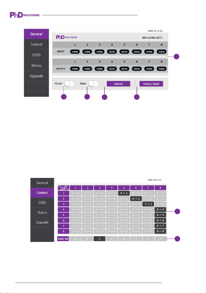
Matrix web GUI page
1
MXC-4K862-HDTL-KIT USER MANUAL
1
2 3
4
5
① Displays the current matrix input and output port status. The “yes” represents connected input
sources or output displays “none” represents no connection.
② Power switch.
The matrix will turn on when this switch is open. The matrix will switch to standby
when this switch is closed
③ Beep switch. When this switch is open the matrix will beep when front panel or remote buttons
are pressed. Close the switch to mute the beeping sound.
④ This button will reboot device.
⑤ This button will factory reset the matrix.
Control page
1
2
① Select the input source to the output display.
② Select the output port audio.
14
www.phdsolutions.co
Page 15

MXC-4K862-HDTL-KIT USER MANUAL
EDID page
① Set EDID mode to input source, then click “Set” button.
② Copy EDID from HDMI output port to input source, then click “Set” button.
③ Open EDID file to input source, then click “Set” button.
④ Click “Refresh” button to refresh current EDID mode. It will display the current input
source EDID mode status.
*See 12. EDID Management for more information
Status page
1
2
① Network Configuration
NET STATUS switch: Obtains the network configuration information, including IP address, Subnet,
Gateway.
DHCP switch:
www.phdsolutions.co
15
Page 16
MXC-4K862-HDTL-KIT USER MANUAL
◆ DHCP selected: Selects DHCP mode : the matrix will obtain a DHCP IP address from the router
Please click “Save Changes” button to save DHCP status.
◆ DHCP unselected: You can manually set the IP, Subnet and Gateway address.
Please click “Save Changes” button to save DHCP status.
(Attention: If you have set a new IP address and clicked the “Save Change” button you will need
set the new IP address in your PC’s web browser and click “Search” to re-enter the Matrix Web
GUI page.)
Net Status button: Press to refresh the current network configuration information to display in the
status log window. .
② Displays the network configuration information.
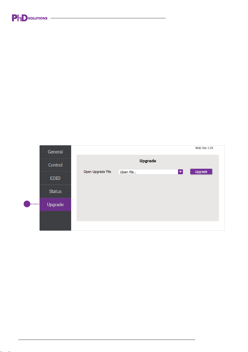
Upgrade page
1
① Open upgrade file to upgrade system firmware. If firmware upgrades are required, they can
be obtained from your distributor or from PhD Solutions technical support.
16
www.phdsolutions.co
Page 17

MXC-4K862-HDTL-KIT USER MANUAL
12. EDID Management
EDID (Extended Display Identification Data) is an exchange (handshake)of data between a source
and a display. The display sends its highest audio and video resolution capabilities to the source.
The source then decides on the best compatible audio and video resolution it needs to send to
the display.
EDID is used to make connecting a digital display to a source a simple plug and play procedure,
however issues do sometimes arise when multiple displays are connected to the same source
or switched to different sources on a video matrix.
By pre-determining the video resolution and audio format of the source and display device you
can reduce the time need for EDID hand shaking thus making switching quicker and more reliable.
You can also force the source to output a certain audio and video resolution if problems with
older or problematic displays arise.
This is done through the advanced EDID management page on the matrix’s web interface.
On this page you can set an EDID mode for each source input on the matrix or copy an EDID
from a display.
EDID mode EDID description
720p,Stereo Audio 2.01
2
3
4
5
6
7
8
9
10
11
12
13
14
15
1080p,Stereo Audio 2.0
1080p,Dolby/DTS 5.1
1080p,HD Audio 7.1
1080i,Stereo Audio 2.0
1080i,Dolby/DTS 5.1
1080i,HD Audio 7.1
3D,Stereo Audio 2.0
3D,Dolby/DTS 5.1
3D,HD Audio 7.1
4K2K30_444,Stereo Audio 2.0
4K2K30_444,Dolby/DTS 5.1
4K2K30_444,HD Audio 7.1
4K2K60_420,Stereo Audio 2.0
4K2K60_420,Dolby/DTS 5.1
www.phdsolutions.co 17
Page 18

MXC-4K862-HDTL-KIT USER MANUAL
16
17
18
19
4K2K60_420,HD Audio 7.1
3
4K2K60_444,Stereo Audio 2.0
4K2K60_444,Dolby/DTS 5.1
4K2K60_444,HD Audio 7.1
13.Matrix Control Protocols & Drivers
The matrix can be controlled via TCP IP, RS232 or IR. For the technical API document and IR
hex files and 3rd party control drivers, these are available for Control4, ELAN, RTI, Crestron etc…
Please visit the PhD website www.phdsolutions.co the information is posted on the relevant
product page.
14.Cable Termination and best practices
Sending High Bandwidth HDMI signals over Cat cable successfully is determined by the bandwidth
capability of the cable network. Most problems with HDMI distribution can be avoided by following
a few basic principles. For 4K signal distribution or long distance runs over HDBaseT™.
we recommend CAT6 UTP solid 23 AWG 550mhz Cable.
1.Use decent quality SOLID UTP CAT cable: a min CAT5E or above.
2.Avoid using CCA (copper clad aluminium) this is cheap cable as its made up of mostly aluminium
and does not carry the bandwidth required for long distance HDMI distribution or CSC 18Gb
compression technology.
3.The CAT cable should be terminated properly with the correct RG45 connectors according to
TIA568B termination standard as this is less prone to electromagnetic interference.
4.Avoid running the Cat cable close to or parallel with electric cables, near machinery or HVAC
compressors.
5.Handle the Cat cable with care, avoid stretching kinking, denting, twisting ,folding or joining it
as this will limit the bandwidth of the cable.
6.Avoid punch down block or Wall plates, these may work but are not recommended as they
add potential resistance to the network and reduce transmission distance and bandwidth.
7.Avoid tight bends and tying cable ties tightly around the CAT cables.
18
www.phdsolutions.co
Page 19

MXC-4K862-HDTL-KIT USER MANUAL
8.If the HDMI signal does not have the correct amount of bandwidth (up to 8gbps for CSC 18gbps
compression), you will not get a picture. If there is any EMI (electromagnetic interference) this
will disrupt the signal. If there is unstable voltage the signal will be disrupted
9.If shielded FTP CAT cables are used, they should be terminated correctly with the correct
shielded connectors, if this is not done properly, more EMI interference will be introduced into
the cable and performance will be inhibited.
RJ45 Pin-Out T568B
1.White Orange 5.White Blue
2.Orange 6.Green
3.White Green 7.White Brown
4.Blue 8.Brown
www.phdsolutions.co 19
Page 20
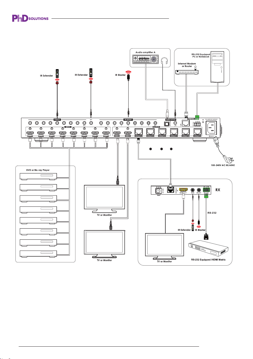
15. Application Diagram
MXC-4K862-HDTL-KIT USER MANUAL
LAN
LAN
20 www.phdsolutions.co
Page 21

MXC-4K862-HDTL-KIT USER MANUAL
16. Troubleshooting
Should you encounter installation difficulties or issues with device communication, the following
checklist of common issues and causes should help resolve your issues. If you still continue to
experience issues, please contact your place of purchase.
NO OR POOR PICTURE QUALITY:
• Connected and powered? Double check all HDMI, Ethernet and power cables are firmly
connected into the correct ports and all devices are correctly powered.
• Cable length? Are you approaching the maximum distance of the cable (70m for 1080p, 40m
for 4K) if so, adjust the picture quality or try using an additional extender kit to go further distance.
Cables bundled together may cause cross talk and further degrade signal quality.
• Signal strength? The use of cable joins, stranded patch panels, wall outlets and stranded patch
leads as interconnects between them, can significantly reduce signal strength. Use solid core
straight through connections wherever possible.
• If you reduce the resolution of the source do you get a picture? If so, this suggests a conflicting
resolution between source and display or a bandwidth capacity issue with your cable. Check all
inputs and outputs share the same resolution capabilities.
• Picture ‘snow’ / HD ‘noise’ signifies a failure to fully establish a signal and can often be caused
by poorly terminated RJ45 connectors or excess cable lengths. Ensure your cable is correctly
wired to 568B standards.
• Pink or off-colour picture? This could be caused by an invalid EDID or the source device failing
to read the EDID from the matrix. Try re-booting matrix and all source devices to force the
re-reading of the EDID.
• Cable quality and condition - HDMI cable/connectors can easily be damaged, and the quality
of material can vary, Always use good quality leads and cables and try swapping cables that are
known to be working to see if this improves your image.
www.phdsolutions.co
21
Page 22

MXC-4K862-HDTL-KIT USER MANUAL
IR Control:
• Are the IR (TX) emitter/blasters and IR (TX) receivers correctly positioned to allow infrared
signals to be transmitted and received? Emitters should be fixed firmly over infrared sensors
of sources. Receivers should be attached to displays ensuring a clear line of sight to the remote
control used to operate.
• Is your remote control powered and sending a signal? As IR is invisible to the naked eye, check
your remote is transmitting a signal by viewing the remote handset sensor througha digital
camera/camera phone. The sensor should flash when a button on the handset is held down.
• IR signal dropout can be experienced due to exterior emissions of infrared radiation. Ensure
emitters and receivers are away from direct sunlight. Halogen lighting and plasma screens may
also interfere with IR signals.
17. PhD Solutions Product Warranty
IMPORTANT INFORMATION ABOUT YOUR RIGHTS AND OBLIGATIONS, AS WELL AS
LIMITATIONS AND EXCLUSIONS THAT MAY APPLY TO YOU. YOUR RIGHTS AND THIS
LIMITED WARRANTY
This Limited Warranty gives you specific legal rights. You may also have other legal rights that
vary by state, province or jurisdiction. The disclaimers, exclusions, and limitations of liability under
this Limited Warranty will not apply to the extent prohibited by applicable law. For a full description
of your legal rights you should refer to the laws applicable in your jurisdiction and you may wish
to contact a relevant consumer advisory service. Should you feel your product does not function
adequately due to defects in materials or workmanship, PhD Solutions (hereby referred to as
“the warrantor”) will, for the length of the period indicated below:
Repair the product with new or refurbished parts, or replace it with a new or refurbished product.
1. WHAT THIS LIMITED WARRANTY COVERS; PERIOD OF COVERAGE PHD Solutions (“PHD
Solutions”), 5th Floor, Barkly Wharf, Le Caudan Waterfront, Port Louis, Mauritius, warrants to
the owner of the enclosed product that the product contained in this box (“Product”) will be free
from defects in materials and workmanship for a period of two years from the date of delivery
following the original purchase (the “Warranty Period”), or if this product has been professionally
22
www.phdsolutions.co
Page 23

MXC-4K862-HDTL-KIT USER MANUAL
installed, the warranty start date is from the date your installer purchased the item, not your
system commissioning date. Please check with your installer for their purchase date. If the
Product fails to conform to this Limited Warranty during the Warranty Period, PHD Solutions will,
at its sole discretion, either (a) repair or replace any defective Product or component; or (b) accept
the return of the Product and refund the money actually paid by the original purchaser for the
Product. Repair or replacement may be made with a new or refurbished product or components,
at PHD Solutions’ sole discretion.
If the Product or a component incorporated within it is no longer available, PHD Solutions may
replace the Product with a similar product of similar function, at PHD Solutions’ sole discretion.
This is your sole and exclusive remedy for breach of this Limited Warranty. Any Product that has
either been repaired or replaced under this Limited Warranty will be covered by the terms of this
Limited Warranty for the longer of ninety (90) days from the date of delivery or the remaining
Warranty Period. This Limited Warranty is transferable from the original purchaser to subsequent
owners, but the Warranty Period will not be extended in duration or expanded in coverage for
any such transfer.
2.WARRANTY CONDITIONS; HOW TO GET SERVICE IF YOU WANT TO CLAIM UNDER
THIS LIMITED WARRANTY
Before being able to claim under this Limited Warranty, the owner of the Product must (a) notify
PHD Solutions of the intention to claim during the Warranty Period and providing a description
of the alleged failure, and (b) comply with PHD Solutions’ return shipping instructions, and (c)
ship the Product at owner’s cost (except where prohibited by applicable law) to PHD Solutions
for repair or replacement. PHD Solutions will have no warranty obligations with respect to a
returned Product if it determines, in its reasonable discretion after examination of the returned
Product that the Product is an Ineligible Product (defined below). PHD Solutions will bear all
costs of return shipping to owner, except with respect to any Ineligible Product, for which owner
will bear all shipping costs.
3. WHAT THIS LIMITED WARRANTY DOES NOT COVER
This warranty does not cover the following (collectively “Ineligible Products”): Products marked
as “sample” or sold “AS IS”; or Products that have been subject to: (a) modifications, alterations,
tampering, or improper maintenance or repairs; (b) handling, storage, installation, testing, or use
not in accordance with the Installation Guide or other instructions provided by PHD Solutions;
(c) abuse or misuse of the Product; (d) breakdowns, fluctuations, or interruptions in electric power
or the telecommunications network;Electro Static Discharge (ESD) or (e)
Acts of God, including
lightning, fire, flood, tornado,
www.phdsolutions.co
23
Page 24

MXC-4K862-HDTL-KIT USER MANUAL
earthquake, or hurricane. This warranty does not cover consumable parts, including batteries,
unless damage is due to defects in materials or workmanship of the Product, or software (even
if packaged or sold with the product). PHD Solutions recommends that you use only authorized
service providers for maintenance or repair. Unauthorized use of the Product or software can
impair the Product’s performance and may invalidate this Limited Warranty. PHD Solutions does
not warrant that operation of the Product will be error-free or uninterrupted or that the Product
will in every case process all data correctly.
4.DISCLAIMER OF WARRANTIES
Except as stated above in this limited warranty, and to the maximum extent permitted by applic-
able law, PHD Solutions disclaims all express, implied, and statutory warranties and conditions
with respect to the product, including the implied warranties of merchantability, fitness for a
particular purpose. To the maximum extent permitted by applicable law, also limits the duration
of any implied warranties or conditions to the duration of this limited warranty.
5.LIMITATION OF DAMAGES
In addition to the above warranty disclaimers, in no event will PHD Solutions be liable for any
consequential, incidental, exemplary, or special damages, including any damages for lost data
or lost profits, arising from or relating to this limited warranty or the product, and PHD Solutions’
total cumulative liability arising from or related to this limited warranty or the product will not
exceed the amount actually paid for the product by the original purchaser.
6.LIMITATION OF LIABILITY
PHD Solutions disclaims all liability of any kind of PHD Solutions’ suppliers. The PHD Solutions
online services (“services”) may provide you information (“product information”) regarding your
products performance and/or peripherals connected to your product (“product peripherals”). The
type of product peripherals that may be connected to your product may change from time to time.
Without limiting the generality of the disclaimers above, all product information is provided for
your convenience, “as is”, and “as available”. PHD Solutions does not represent, warrant, or
guarantee that product information will be available, accurate, or reliable. You use all product
information, the services, and the product at your own discretion and risk. You will be solely
responsible for (and PHD Solutions disclaims) any and all loss, liability, or damages, including
to your hvac system, plumbing, home, product, product peripherals, computer, mobile device,
and all other items and pets in your home, resulting from your use of the product information,
services, or product. Product information provided by the services is not intended as a substitute
for direct means of obtaining the information.
24
www.phdsolutions.co
Page 25

MXC-4K862-HDTL-KIT USER MANUAL
7.VARIATIONS THAT MIGHT APPLY TO THIS LIMITED WARRANTY
Some jurisdictions do not allow limitations on how long an implied warranty lasts or exclusions/
limitations on incidental or consequential damages, so some of the limitations set out above may
not apply to you.
8.COPYRIGHT NOTICE
No part of this document may be reproduced, transmitted, transcribed, stored in a retrieval system,
or any of its part translated into any language or computer file, in any form or by any means
(electronic, mechanical, magnetic, optical, chemical, manual, or otherwise) without express
written permission and consent from PHD Solutions.
© Copyright 2019 PHD Solutions. All Rights Reserved.
VER 1.0_ 06062019 MXC-4K862-HDTL-KIT User Manual -June 2019
www.phdsolutions.co
Series
www.phdsolutions.co 25
 Loading...