


Operating Instructions
Ultra-Low Temperature Freezer
MDF-DU900V
Please read the operating instructions carefully before using this product, and keep the operating
instructions for future use.
See page 64 for model number.


CONTENTS
INTRODUCTION ········································································· 2
PRECAUTIONS FOR SAFE OPERATION ········································· 3
LABELS ON UNIT ········································································ 7
SYMBOLS ON UNIT ····································································· 7
ENVIRONMENTAL CONDITIONS ··················································· 8
INTENDED USE AND PRECAUTIONS ············································· 8
FREEZER COMPONENTS
Unit ······················································································ 9
LCD touch panel ··································································· 11
Remote alarm terminal ··························································· 13
AIR INTAKE PORT ····································································· 14
INSTALLATION SITE ·································································· 14
INSTALLATION ········································································· 16
START-UP OF UNIT ·································································· 17
Operation during power failure ················································· 18
Operation after recovery from power failure ································· 18
BASIC OPERATION ON LCD TOUCH PANEL ································· 19
BASIC PARAMETERS
How to input numerical value and alphanumeric character ·············· 20
Setting Temperature, High Alarm and Low Alarm ························· 22
Setting operation control mode ················································· 23
Setting key lock ···································································· 25
Removing key lock ································································· 27
ALARM PARAMETERS ······························································ 28
OPERATION/ALARM LOG
Setting log interval ································································· 31
Displaying operation log ·························································· 32
Exporting operation log ·························································· 35
Displaying alarm log ······························································· 38
Exporting alarm log ································································ 40
OTHER PARAMETERS
Setting date and time······························································ 43
Setting brightness and sleep ···················································· 44
OPERATION MONITOR SYSTEM ················································ 46
ALARMS, SAFETY, AND SELF-DIAGNOSIS ··································· 47
ROUTINE MAINTENANCE ·························································· 50
Cleaning of cabinet ································································ 50
Cleaning of condenser filter ···················································· 50
Defrosting of chamber ··························································· 51
Cleaning of air intake port ······················································ 52
CALIBRATION ·········································································· 52
REPLACEMENT OF WEAR-OUT PARTS
Replacing the battery for power failure alarm ······························· 53
Replacing the battery for backup cooling kit ································ 53
TROUBLESHOOTING ································································ 54
DISPOSAL OF UNIT ·································································· 55
Recycle of battery ································································· 55
TEMPERATURE RECORDER (OPTION) ········································ 60
SMALL INNER DOOR (OPTION) ·················································· 60
INVENTORY RACK (OPTION) ······················································ 61
BACKUP COOLING KIT (OPTION) ················································ 62
SPECIFICATIONS ····································································· 63
PERFORMANCE ······································································· 64
SAFETY CHECK SHEET····························································· 65
1

INTRODUCTION
■ Read the operating instructions carefully before using the product and follow the instructions for safe
operation.
■ PHC Corporation takes no responsibility for safety if the product is not used as intended or is used with
any procedures other than those given in the operating instructions.
■ Keep the operating instructions in a suitable place so that they can be referred to as necessary.
■ The operating instructions are subject to change without notice for improvement of performance or
function.
■ Contact our sales representative or agent if any page of the operating instructions is lost or the page
order is incorrect, or if the instructions are unclear or inaccurate.
■ No part of the operating instructions may be reproduced in any form without the express written
permission of PHC Corporation.
IMPORTANT NOTICE
PHC Corporation guarantees this product under certain warranty conditions. However, please note that
PHC Corporation shall not be responsible for any loss or damage to the contents of the product.
2

PRECAUTIONS FOR SAFE OPERATION
It is imperative that the user complies with the operating instructions
as it contains important safety advice.
Items and procedures are described so that you can use this unit correctly and safely.
If the precautions advised are followed, this will prevent possible injury to the user and
any other person.
Precautions are illustrated in the following way:
WARNING
Failure to observe WARNING signs could result in a hazard to personnel
possibly resulting in serious injury or death.
CAUTION
Failure to observe CAUTION signs could result in injury to personnel and
damage to the unit and associated property.
Symbol shows;
T
Be sure to keep the operating instructions in a place accessible to users of this unit.
his symbol means caution.
This symbol means an action is prohibited.
This symbol means an instruction must be followed.
WARNING
As with any equipment that uses CO
of the equipment. It is important that you assess the work site to endure there is suitable and
sufficient ventilation. If restricted ventilation is suspected, then other methods of ensuring a safe
environment must be considered. These may include atmosphere monitoring and warning
devices.
gas, there is a likelihood of oxygen depletion in the vicinity
2
3

PRECAUTIONS FOR SAFE OPERATION
Do not use the unit outdoors. Current leakage or electric shock may result if the unit is exposed to
rain water.
Only qualified engineers or service personnel should install the unit. The installation by
unqualified personnel may cause electric shock or fire.
Install the unit on a sturdy floor and take an adequate precaution to prevent the unit from
turning over. If the floor is not strong enough or the installation site is not adequate, this may result
in injury from the unit falling or tipping over.
Never install the unit in a humid place or a place where it is likely to be splashed by water.
Deterioration of the insulation may result which could cause current leakage or electric shock.
Never install the unit in a flammable or volatile location. This may cause explosion or fire.
Never install the unit where acid or corrosive gases are present as current leakage or electric
shock may result due to corrosion.
Always ground (earth) the unit to prevent electric shock. If the power supply outlet is not
grounded, it will be necessary to install a ground by qualified engineers.
Never ground the unit through a gas pipe, water main, telephone line or lightning rod. Such
grounding may cause electric shock in the case of an incomplete circuit.
Connect the unit to a power source as indicated on the rating label attached to the unit. Use
of any other voltage or frequency other than that on the rating label may cause fire or electric shock.
Never store volatile or flammable substances in this unit if the cylinder cannot be sealed. These
may cause explosion or fire.
Do not insert metal objects such as a pin or a wire into any vent, gap or any outlet on the unit.
This may cause electric shock or injury by accidental contact with moving parts.
Use this unit in safe area when treating the poison, harmful or radiate articles. Improper use
may cause bad effect on your health or environment.
Turn off the power switch (if provided) and disconnect the power supply to the unit prior to any
repair or maintenance of the unit in order to prevent electric shock or injury.
Do not touch any electrical parts (such as power supply plug) or operate switches with a wet
hand. This may cause electric shock.
WARNING
4

WARNING
Ensure you do not inhale or consume medication or aerosols from around the unit at the time of
maintenance. These may be harmful to your health.
Never splash water directly onto the unit as this may cause electric shock or short circuit.
Never put cylinders with liquid on the unit as this may cause electric shock or short circuit when
the liquid is spilled.
Never bind, process, or step on the power supply cord, or never damage or break the power
supply plug. A broken supply cord or plug may cause fire or electric shock.
Do not use the supply cord if its plug is loose. Such supply cord may cause fire or electric shock.
Never disassemble, repair, or modify the unit yourself. Any such work carried out by an
unauthorized person may result in fire, or electric shock or injury due to a malfunction.
Disconnect the power supply plug if there is something wrong with the unit. Continued
abnormal operation may cause electric shock or fire.
Do not position this unit and the other unit so that it is difficult to operate the disconnection of
the power supply plug. Failure to disconnect the power supply plug may cause fire if there is
something wrong with the unit.
When removing the plug from the power supply outlet, grip the power supply plug, not the cord.
Pulling the cord may result in electric shock or fire by short circuit.
Disconnect the power supply plug before moving the unit. Take care not to damage the power
cord. A damaged cord may cause electric shock or fire.
Disconnect the power supply plug when the unit is not used for long periods. Keeping the
connection may cause electric shock, current leakage, or fire due to the deterioration of insulation.
If the unit is to be stored unused in an unsupervised area for an extended period, ensure that
children do not have access and that doors cannot be closed completely with a key.
The disposal of the unit should be accomplished by appropriate personnel. Remove doors to
prevent accidents such as suffocation.
Do not put the packing plastic bag within reach of children as suffocation may result.
Connect the power supply plug to the power source firmly after removing the dust on the plug.
A dusty plug or improper insertion may cause a heat or ignition.
Do not touch the condenser directly when the filter is removed for cleaning. This may cause injury
by hot surface.
5

PRECAUTIONS FOR SAFE OPERATION
This unit must be plugged into a dedicated circuit protected by branch circuit breaker.
Use a dedicated power source as indicated on the rating label attached to the unit. A
multiple-tap may cause fire resulting from abnormal heating.
Never store corrosive substances such as acid or alkali in this unit if the container cannot be
sealed. These may cause corrosion of inner components or electric parts.
Check the setting when starting up of operation after power failure or turning off of power
switch. The stored items may be damaged due to the change of setting.
Be careful not to tip over the unit during movement to prevent damage or injury.
Prepare a safety check sheet (copy the last page) when you request any repair or maintenance for
the safety of service personnel.
Never touch the storage items with wet hands. Touching with the wet hands may cause frostbite.
CAUTION
6

LABELS ON UNIT
Warning safety labels applied to the ultra-low temperature freezer
Users are advised to avoid accidents by carefully reading the warnings and cautions contained on
warning labels at key locations on the interior and exterior of the ultra-low temperature freezer.
Possible
Danger
Personal
injury
Warning/Caution Type
Location of Danger
Frostbite and frost
Interior
Warning/Caution Label Description of Danger
Frostbite and frost caution label.
Sample
damage
Sample
damage
Personal
injury
SYMBOLS ON UNIT
The symbols are attached to the ultra-low temperature freezer. The following table describes the
symbols.
Chamber temperature
Interior
Chamber temperature
Interior
Negative pressure
release
Interior
This symbol is attached to covers that access high-voltage electrical components to
prevent electric shock. Only a qualified engineer or service personnel should be
allowed to open these covers.
Forgets to close a door and latch.
Rise in temperature is prevented.
Door cannot open.
This symbol indicates that caution is required. Refer to product documentation for
details.
This symbol indicates an earth.
This symbol means “ON” for a power switch.
This symbol means “OFF” for a power switch.
7

ENVIRONMENTAL CONDITIONS
This equipment is designed to be safe at least under the following conditions (based on the IEC 61010-1):
■ Indoor use;
■ Altitude up to 2000 m;
■ Ambient temperature 5
■ Maximum relative humidity 80% for temperature up to 31
o
at 40
C;
■ Mains supply voltage fluctuations up to ±10% of the nominal voltage;
■ Transient overvoltages up to the levels of OVERVOLTAGE CATEGORY II;
■ Temporary OVERVOLTAGES occurring on the mains supply;
■ Applicable pollution degree of the intended environment (POLUTION DEGREE 2 in most cases);
o
C to 40oC;
o
C decreasing linearly to 50% relative humidity
INTENDED USE AND PRECAUTIONS
This equipment is designed for low temperature storage of human cells, organs, plasma and DNAs.
■ The effective storage period depends on the sample condition and storage temperature. It is
necessary to determine the storage temperature and period suitable for the purpose.
■ For the live cells, the lower storage temperature should be required for long term storage. It is
recommended to store the live cells at -130
o
C or lower.
8

FREEZER COMPONENTS
Unit
13
12 (inside)
Front side
11
12
10 (inside)
18
19
17
9
7
8
16 15
1
2
3
4
5
6
14
Rear side
9

FREEZER COMPONENTS
1. Outer door: To open the outer door, grip the outer door latch. When closing, lock the outer door
latch completely.
2. Inner door: The operation of the inner door should be quick to minimize the temperature rise in
chamber. Lock the inner door latch completely when the inner door is closed. The inner door is
removable for cleaning or defrosting. See page 51.
3. Outer door latch: Always lock the outer door latch when the outer door is closed. A padlock is also
available.
4. Keyhole: Turn clockwise to 180
5. Inner door latch: Always lock the inner door latch when the inner door is closed.
6. Magnetic door gasket: This provides a tight door seal and prevents cold air leak. Keep clean.
7. Air intake vent (grille): Do not block this vent to keep the proper cooling performance.
8. Leveling feet: These are screw bolts used to install and fix the unit. Adjust the height of the leveling
feet by turning the screw bolts until 2 front casters are away from the floor.
9. Caster: 4 casters are provided to facilitate moving of the cabinet. For the installation, adjust the
leveling foot so that the front 2 casters cannot contact with the floor.
10. Condenser filter (behind the grille): This filter prevents the dust from accumulating on the
condenser. The dusty condenser filter may cause failure of refrigerating device. Clean the condenser
filter once a month. See page 50.
11. Space for temperature recorder: A temperature recorder (optional component) can be attached
here. See page 60.
12. Access port (rear and bottom): This is used for leading a cable and sensor of a measuring
equipment, or nozzle of backup cooling kit to chamber.
Replace the cap and insulation after using the access port. Improper replacement may cause poor
cooling or condensation around the outside of access port.
13. Air intake port: Used for open the outer door immediately after closing the outer door. See page 14.
14. Fixture (on back side): 2 fixtures are provided as spacers between the cabinet and wall and also
serve as hooks to fix the unit. See page 16.
15. Battery switch: This is a switch for a battery for power failure alarm. Normally, turn on this switch.
Be sure to turn off this switch if the freezer is not in operating for the long period (over one month).
16. Remote alarm terminal: This is used to notice an alarm condition of the unit to remote location.
See page 13.
17. Power switch: This is for turning ON/OFF the power to the unit.
18. LCD touch panel: See page 11~12.
19. USB port: Insert USB memory to export operations and alarms log. See page 35~42.
Note: It is impossible to use USB memory which is required password input.
Note:
3 shelves are packaged at the bottom of the chamber. Set the shelves on the shelf stoppers at the
standard location firmly. The upward edge should be upside.
Refer to page 61 for the attachment of shelf stopper when changing the location of shelf stopper.
o
with a key and the outer door is securely locked.
10

LCD touch panel
The following display (called the Top screen) will appear when the power switch is turned ON.
Note: It takes approximately 20 seconds until Top screen is displayed.
1 2 3
1. Present temperature display field: The current chamber temperature is displayed.
Note: An integer rounded off below a decimal point is displayed.
2. Set temperature value display field: The set value of chamber temperature is displayed. Default
setting: -80
3. Present date/time display field: Normally, this indicator shows date and time. The date and time is
simply set when the freezer is shipped from the factory. Refer to page 43 for details.
4. Filter alarm indicator: This indicator is lit when the excessive dust is accumulated on the condenser filter.
When this indicator is lit, clean the condenser filter following the procedure on page 50.
5. Alarm display: Refer to page 47~48 for details of alarms.
Normal condition: “Normal” is displayed.
Alarm-activated, buzzer-delayed: “Alarm” is displayed alternately in normal characters and reverse video.
Alarm-activated, buzzer-sounding: “Warning” is displayed alternately in normal characters and reverse video.
6. Door (opening/closing) display: Refer to page 47
Open: “Open” is displayed alternately in normal characters and reverse video.
Close: “Closed” is displayed.
7. Backup display: (It is displayed only when an optional backup cooling kit MDF-UB6B is installed)
ON/OFF of the backup power switch is displayed (refer to page 62).
ON: “Switch ON” is displayed.
OFF: “Switch OFF” is displayed.
o
C.
4
5
6
7
11

FREEZER COMPONENTS
8
11 10
8. Message display field: The information of the operation monitor system, alarms or errors are
displayed when fault occurs. Refer to page 46~48.
9. Message select key: When there are a number of alarm, errors or information of the operation monitor
system, the message on the screen is changeable.
10. Menu key: Press this key to lead the Menu screen. It is possible to set various setting on the Menu
screen. Refer to page 19.
11. Buzzer key: Press this key to silence the buzzer. However, when the ring back is ON, the buzzer will
sound again when the ring back passed and the alarm state still continues. Refer to page 29 and 49.
9
12

Remote alarm terminal
The alarm of this unit can be informed at a remote location from this unit by connecting the external alarm
device to the remote alarm terminals. For the type and behavior of remote alarm output, refer to page
47~48.
The terminal of the remote alarm is installed at the
right side of the unit (See the figure on the point).
The alarm is outputted from this terminal. Contact
capacity is DC 30 V, 2 A.
When Buzzer key is pressed, the behavior of the
remote alarm is showed in Table.1.
Note: In the door alarm, the remote alarm does not
work. Refer to page 47.
Table 1 The behavior of the remote alarm when pressing Buzzer key
Remote Alarm setting
(Refer to page 28~30)
ON:
Non-interlock with Buzzer key
OFF:
Interlock with Buzzer key
Use a twisted sealed wire for the connection.
Type; UL 2343, UL 2448, UL 2464, UL2552, UL2623.
Length: 30 m max.
Connecting
terminal
COM.-N.C. Close Open Open (Maintain in abnormality)
COM.-N.O. Open Close Close (Maintain in abnormality)
COM.-N.C. Close Open Close (Return to normal)
COM.-N.O. Open Close Open (Return to normal)
Normal
condition
(Including in the cases of power outage and
Remote alarm terminal
Abnormal condition
of where the power plug is pulled out.)
When pressing Buzzer key
13

AIR INTAKE PORT
Opening the outer door immediatery after closing it, may make
feel heavy. The cause is the pressure difference between inside
and outside the unit that caused by contraction of the chamber air
which cooled down rapidly. When the outer door is closed and
opened soon, the outer door is easy to open with the following
process.
1. Turn the cap on the left side counterclockwise about two laps.
(Or remove the cap.)
2. Allow about twenty seconds before open the outer door.
3. Close (or replace) the cap when the door operation is
completed.
The outer door may not open in the above method when there are frost and ice in the air intake port. In
that case, remove the cap and check the frost inside the air intake port. Remove the frost inside the air
intake port with the enclosed "stick for air intake port cleaning" when the excessive frost is built in the air
intake port. Clean the air intake port every month even when there is no frost in the air intake port.
Refer to page 52 for the cleaning.
Two laps
Cap
INSTALLATION SITE
CAUTION
For removing the frost in the air intake port, do not use a tool with sharp edge such as a knife or a screw
driver.
Replace the cap when the air intake port is not used. Improper replacement may cause rise of chamber
temperature or condensation around the air intake port.
To operate this unit properly and to obtain maximum performance, install the unit in a location with the
following conditions:
■ A location not subjected to direct sunlight
Do not install the unit under direct sunlight. Installation in a location subjected to direct sunlight cannot
obtain the intended performance.
■ A location with adequate ventilation
Leave at least 10 cm around the unit for ventilation. Poor ventilation will result in a reduction of the
performance and consequently the failure.
■ A location away from heat generating sources
Avoid installing the unit near heat-emitting appliances such as a heater or a boiler etc. Heat can decrease
the intended performance of the unit.
14

■ A location with little temperature change
Install the unit under stable ambient temperature. The allowable ambient temperature is between +5
and +30
■ A location with a sturdy and level floor
Always install the unit on a sturdy and level floor. The uneven floor or tilted installation may cause failure
or injury. Install the unit in stable condition to avoid the vibration or noise. Unstable condition may cause
vibration or noise.
o
C.
WARNING
Install the unit on a sturdy floor. If the floor is not strong enough or the installation site is not
adequate, this may result in injury from the unit falling or tipping over.
Select a level and sturdy floor for installation. This precaution will prevent the unit from tipping.
Improper installation may result in water spillage or injury from the unit tipping over.
■ A location not prone to high humidity
Install the unit in the ambient of 80 %R.H. or less humidity. Installation under high humidity may cause
current leakage or electric shock.
o
C
WARNING
Do not use the unit outdoors. Current leakage or electric shock may result if the unit is exposed to
rain water.
Never install the unit in a humid place or a place where it is likely to be splashed by water.
Deterioration of the insulation may result which could cause current leakage or electric shock.
■ A location without flammable or corrosive gas
Never install the unit in a location where it will be exposed to inflammable or corrosive gas. This may
cause explosion or fire or may result in the current leakage or electric shock by the corrosion of the
electrical components.
■ A location without corrosive substance
Never install the unit in a location where corrosive substance such as sulfur-contained compound may
generate (ex. near a sink). The corrosion of copper pipe of the cooling circuit may result in the failure of
the unit.
■ A location without the possibility of anything fall
Avoid installing the unit in the location where anything can fall down onto the unit. This may cause the
breakdown or failure of the unit.
15

INSTALLATION
1. Remove the packaging materials and tapes
Remove all transportation packaging materials and tapes. Open the doors and ventilate the unit. If the
outside panels are dirty, clean them with a diluted neutral dishwashing detergent (Undiluted detergent can
damage the plastic components. For the dilution, refer to the instruction of the detergent). After the
cleaning with the diluted detergent, always wipe it off with a wet cloth. Then wipe off the panels with a dry
cloth.
Note: Remove the cable tie banding the power supply cord. Prolonged banding may cause the corrosion
of the cord coating.
2. Adjust the leveling feet
Stretch the leveling feet by rotating them as shown in Fig. 1 to contact them to the floor. Ensure the unit
is installed horizontally.
3. Fix the unit
Two fixtures are attached to the rear of the frame. Fix the frame to the wall with these fixtures and rope
or chain. (Fig. 2)
Shrink
Stretch
4. Setting the shelves
3 shelves are packaged at the bottom of the chamber. Set the shelves on the shelf stoppers at the
standard location firmly. The upward edge should be upside.
5. Ground (earth)
The ground (earth) is for preventing the electric shock in the case of unexpected deterioration of the
electrical insulation. Always ground the unit at the time of installation.
6. Installation branch circuit breaker
This unit is to be connected to a dedicated circuit protected by branch circuit breaker.
Contact our sales representative or agent.
Leveling feet
Fig.1
Fixture
Fig. 2
WARNING
Use a power supply outlet with ground (earth) to prevent electric shock. If the power supply outlet is
not grounded, it is necessary to install a ground by qualified engineers.
Never ground the unit through a gas pipe, water main, telephone line or lightning rod. Such
grounding may cause electric shock in the case of an incomplete circuit.
16

START-UP OF UNIT
Use the following procedure to start trial operation or actual operation of the unit.
1. Make sure that both of the power switch and the battery switch for power failure alarm are OFF (factory
setting is OFF).
Note: When the power switch is ON and the battery switch for power failure alarm is ON, the power
failure alarm is activated (refer to page 47).
2. (When an optional backup cooling kit MDF-UB6B is installed) Turn OFF the backup power switch.
3. Before putting some contents to cryopreserve into the chamber, connect the power supply cord to the
outlet.
4. Turn ON the power switch to start operation of the unit.
5. Turn ON the battery switch for power failure alarm.
Note: When the battery switch for power failure alarm is OFF, “Err09: Battery Switch is OFF.” is displayed
in the message display field. By turning ON the battery switch for power failure alarm, this message
disappears.
6. Set the chamber temperature and the high/low alarm (refer to page 22~23).
Note: Keep the ambient temperature between 5
set temperature when the ambient temperature is higher than 30
7. Make sure that chamber temperature is cooled to the set temperature.
8. Do the alarm test. Make sure that the buzzer sounds by pressing Buzzer key for 5 seconds. Press
Buzzer key again to stop the buzzer and the alarm test finishes.
9. (When an optional backup cooling kit MDF-UB6B is installed) After the chamber temperature reaches
the set temperature, turn ON the backup power switch.
Note: When operating this unit for the first time or after not using it for an extended period of time, it is
required 3 days (72 hours) operation of unit before using the backup cooling kit. The capacity of internal
battery for backup cooling kit may be less or flat by electric discharge.
10. (When an optional backup cooling kit MDF-UB6B is installed) Set the injection set temperature of the
backup cooling kit by adjusting the temperature setting knob.
11. Put the contents to cryopreserve into the chamber.
Note:
• Do not put a large amount of contents to cryopreserve at a time. Put little by little to prevent rapid rise of
the chamber temperature.
• Do not put a large amount of warm contents to cryopreserve. The rise of the chamber temperature may
have a bad influence on the contents in the unit.
• In case some optional inventory racks are in the chamber, be careful not to drop inventory rack when
pulling out it.
o
C to 30 oC. The chamber temperature may not reach
o
C.
17

START-UP OF UNIT
Operation during power failure
When the battery switch for power failure is ON, during a power failure the behavior of this unit is as
follows.
●The power failure alarm is activated (refer to page 47).
Press Buzzer key to silence the buzzer of the power failure alarm. In case the ring back is turned ON,
buzzer sounds again when a power failure still continues after ring back set time passed (refer to page
29).
●LCD touch panel is turn OFF (refer to page 47).
By touching the LCD touch panel, it lights in the set brightness for 5 seconds.
●The High/Low Alarm is ready to activate during a power failure (refer to page 22~23 and 47).
(While the LCD touch panel is lighting after touching) The message of the High/Low Alarm is displayed in
the message display field, and “Alarm” (or “Warning”) is displayed alternately in normal characters and
reverse video in the alarm display. The buzzer and the remote alarm (although it is of the power failure
alarm) are already activated.
●The clock function does not stop.
●Operation log data and alarm log data during a power failure is saved.
Note: When the capacity of the battery for power failure alarm is flat during a power failure, subsequent
operation log data and alarm log data is not saved.
Operation after recovery from power failure
The set value is memorized by nonvolatile memory. Accordingly, the chamber resumes the operation with
setting before power failure.
Note:
• It may take up to 1 minute until the LCD touch panel lights after recovery from power failure.
• All products start at the same time as the recovery from the power failure, so that, the temporary voltage
drop may have a bad influence on the starting of this unit. To prevent this situation, set the appropriate
compressor delay time of this unit (refer to page 24).
Although the power failure alarm is canceled at the
recovery of the power failure, in order to remind
that power failure had happened, buzzer is
sounding and “Alarm” is displayed alternately in
normal characters and reverse video in the alarm
display (refer to page 49). By pressing Buzzer key,
the alarm display returns to “Normal” and the
buzzer stops.
Note: It is possible to confirm the past alarms in
the “Displaying alarm log” (refer to page 38~39).
18

BASIC OPERATION ON LCD TOUCH PANEL
A
♦Message select key:
(Operate) Changing some messages
♦Buzzer key: (Operate) Silencing the buzzer
(Alarm is not canceled except for some alarms; page 49)
●Operation from Menu key
■Menu screen
♦Set →
♦Log →
♦Chart →
♦Actual Temp. (Display) Chamber temp. log graph (can be exported)
♦Door Opening (Display) Door opening log graph (can be exported)
♦Actual Temp. (Export) Chamber temperature log
♦Door Opening (Export) Door opening log
♦Setting (Setting) Log interval, Unique ID
♦Alarm (Display)
♦Alarm Export (Export) Alarm log
♦Key Lock →
♦Tools →
♦Operation Setting (Setting) Comp. delay time
♦Alarm Setting (Setting) Alarm delay, ring back, remote alarm etc.
♦DAQ Setting Do not press (It is not possible to set.)
♦Date & Time (Setting) Date, time
♦Brightness/Sleep (Setting) Brightness, sleep ON/OFF etc.
■Temp. Setting screen
■Log screen
■Chart screen
Data
♦
Export
■Key Lock screen
■Tools screen
→
■Export screen
(Setting) Temp., High Alarm, Low Alarm
larm log (can be exported)
(Setting) Key lock ON/OFF, password
Page
22
32
32
35
35
31
38
40
25
23
28
43
44
~23
~34
~34
~37
~37
~32
~39
~42
~27
~24
~30
~45
19
BASIC PARAMETERS
How to input numerical value and alphanumeric character
On each screen in the LCD touch panel, it may be necessary to input numerical value or alphanumeric
characters.
●When inputting numerical value
1. By pressing numeric input box, numeric input
window is displayed.
2. Press Numeric key or Up/Down key to input
numerical value, and press OK key.
●Key description
• Numeric key (0~9): Input numerical value.
• Up/Down key (▲/▼): Increases or decreases the numerical value displayed in the numeric input box.
• Clear key: Deletes the numerical value displayed on the numeric input box.
• Cancel key: Stops inputting on the numeric input box and closes the input window.
Note: Up/Down key may not be displayed.
Numeric input box
Numeric input window
20

●When inputting alphanumeric characters
1. By pressing alphanumeric input box,
alphanumeric input window is displayed.
2. Press alphabetic key and numeric key to input
alphanumeric characters, and press OK key.
●Key description
• Alphabetic key (A~Z, Space): Input alphabetic characters or spaces.
• Numeric key (0~9): Input numerical values.
• UC/LC key (A a): Change UC/LC of alphabetic key.
• Left/Right key ( / ): Move the cursor to left/right.
• Delete key: Delete an alphanumeric character on the left side of the cursor.
• Cancel key: Stops inputting on the alphanumeric input box and closes the alphanumeric input window.
Note: While the alphanumeric input window is open, it is not possible to operate Top key and Back key.
Alphanumeric input box
Alphanumeric input window
21

BASIC PARAMETERS
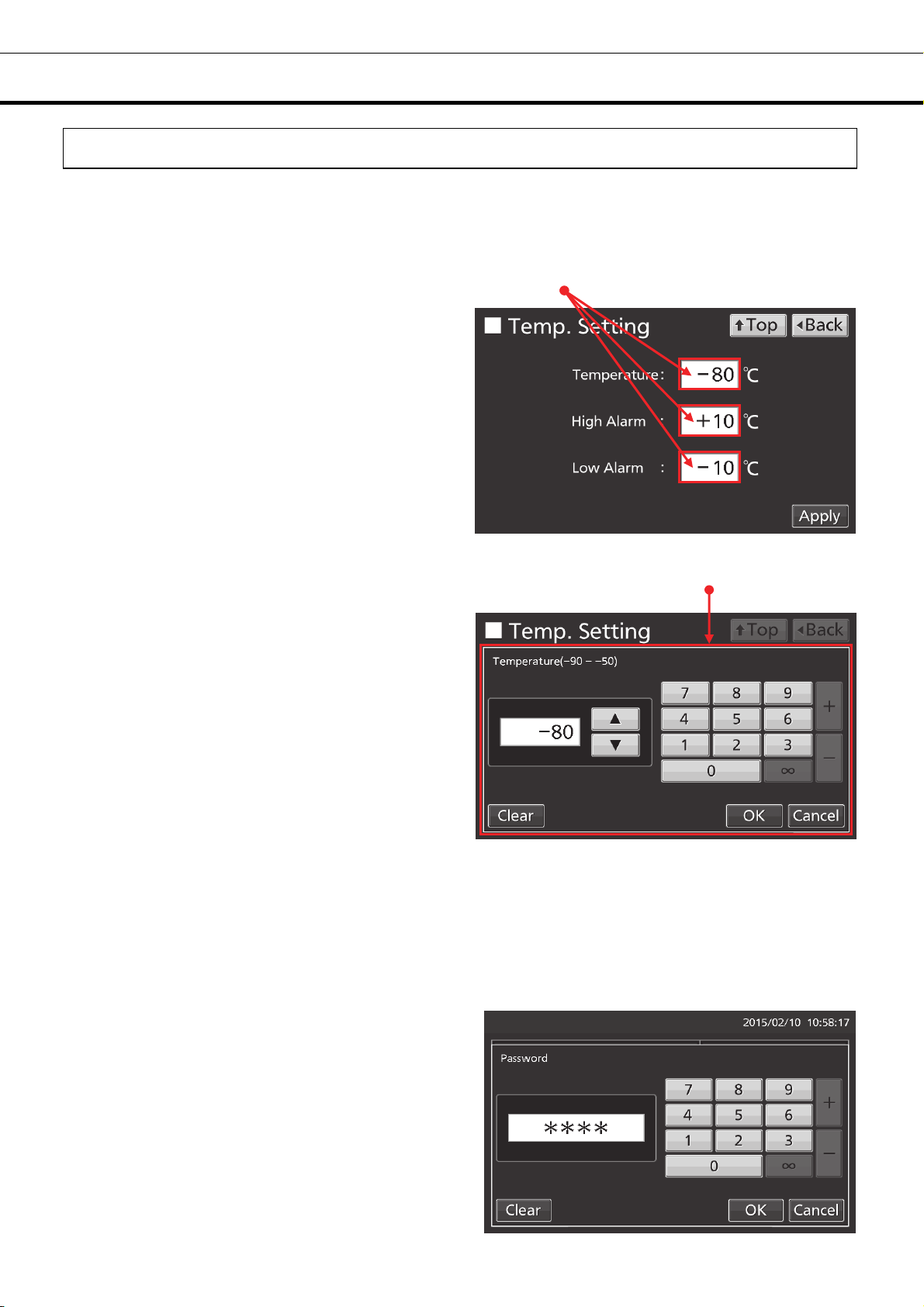
Setting Temperature, High Alarm and Low Alarm
Set the Temperature, High Alarm and Low Alarm for normal operation according to the following
procedure. The unit automatically starts operation using these settings after power-on.
1. Press Menu key to lead the Menu screen.
2. Press Set key to lead the Temp. Setting
screen.
3. Input each parameter. Press Apply key to save
the input value. The display returns to the Menu
screen.
●Each parameter setting
• Temperature: Set value of chamber temperature.
Settable range: -90
• High Alarm: When the chamber temperature exceeds the High Alarm set temperature (= the set
temperature + the set value of High Alarm)*, the High Alarm is activated.
Settable range: +5
• Low Alarm: When the chamber temperature falls below the Low Alarm set temperature (= the set
temperature - the set value of Low Alarm)*, the Low Alarm is activated.
Settable range: -40
o
C~-50 oC, Control range: -86 oC~-50 oC, factory setting: -80 oC.
o
C~+40 oC, factory setting: +10 oC.
o
C~-5 oC, factory setting: -10 oC.
22

* The current chamber temperature is the value rounded off below a decimal point, so the High/Low
Alarm may be activated when the value of the current chamber temperature is equal to the High/Low
Alarm set temperature.
4. On the Menu screen, press Back key to return to the Top screen.
Setting operation control mode
1. Press Menu key to lead the Menu screen.
2. Press Tools key to lead the Tools screen.
3. Press Operation Setting key to lead the
Operation Setting screen.
23

BASIC PARAMETERS
4. Input each parameter. Press Apply key to save
the input value and setup. The display returns to
the Tools screen.
●Each setting
• Compressor Delay:
The time from turning ON this unit until starting its compressor. This unit is required a large electric power
at the moment its compressor starts. When some units are in a same room, set so as to be shifted to
each other the compressor delay times, to prevent the simultaneous start of all compressors after power
failure. Settable range: 3 minutes~15 minutes, factory setting: 3 minutes.
5. Press Top key to return to the Top screen.
24

Setting key lock
1. Press Menu key to lead the Menu screen.
2. Press Key Lock key to lead the Key Lock
screen.
3. On the Key Lock screen, it is possible to set
each setting of key lock (refer to next page).
Press Apply key to change key lock ON and to
save the password. The display returns to the
Menu screen.
25
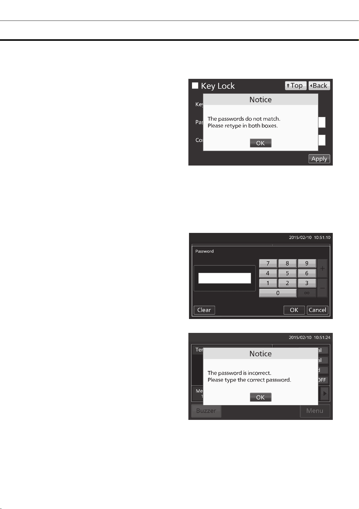
BASIC PARAMETERS
●Each setting of key lock
• Key Lock: By holding Key Lock slide key and sliding it to the right, Key Lock turns to ON.
• Password: The number (Max. 6 digits) inputted here are registered the release password of Key Lock.
• Confirm Password:
To prevent erroneous input, input the same
password as Password input box. When inputting
different password, Notice dialog box is displayed.
Press OK key and input the correct password.
Note: Manage the release password of Key Lock properly.
4. On the Menu screen, press Back key to return to the Top screen.
●Operation for Keylock-ON
• When pressing Menu key, Password input box is
displayed, and input of the release password of
Key Lock is required.
• When the inputted password is incorrect, Notice
dialog box is displayed. Press OK key, and then
input the correct password.
26

Removing key lock
1. By pressing Menu key, the Password input
window is displayed.
2. On Password input box, input the set release
password of Key Lock, and press OK key to lead
the Menu screen.
3. Press Key Lock key to lead the Key Lock
screen.
4. On the Key Lock screen, by holding Key Lock
slide key and sliding to the left, change to OFF.
Press Apply key to turn the key lock OFF. The
display returns to the Menu screen.
Note: The release password of key Lock is
deleted.
5. On the Menu screen, press Back key to return to the Top screen.
27
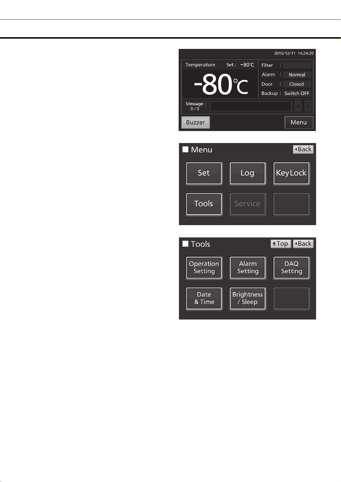
ALARM PARAMETERS
1. Press Menu key to lead the Menu screen.
2. Press Tools key to lead the Tools screen.
3. Press Alarm Setting key to lead the Alarm
Setting screen.
28

4. On the Alarm Setting screen, it is possible to
set each setting. Press Apply key to save the
input value and setup. The display returns to the
Tools screen.
●Each setting
• Alarm Delay:
The function is that when the unit is in the alarm state of High Alarm or Low Alarm, the alarm buzzer will
sound after the alarm delay set time passed.
Settable range: 0 minute~15 minutes, factory setting: 15 minutes.
Note: When the unit is recovered from the alarm state within the alarm delay time, the buzzer does not
sound after the elapse of the alarm delay.
• Door Delay:
The function is that when the unit is in the alarm state of door, the alarm buzzer will sound after the alarm
delay set time passed. Settable range: 0 minute~15 minutes, factory setting: 2 minutes.
Note: When the unit is recovered from the alarm state within the door alarm delay time, the buzzer does
not sound after the elapse of the door alarm delay.
• Ring Back:
The function is that the alarm buzzer sounds again when the alarm state still continues after the ring back
set time passed even though the alarm buzzer was stopped by pressing Buzzer key. By holding and
sliding Ring Back slide key to the right, the Ring Back is turned to ON.
Settable range: 1 minute~99 minutes, factory setting: 30 minutes.
Note: At Door alarm, the alarm is not re-activated because the alarm itself is deactivated by pressing
Buzzer key (refer to page 49).
• Remote Alarm:
The function is that the remote alarm is continued even though the buzzer is stopped by pressing Buzzer
key. By holding and sliding Remote Alarm slide key to the right, the Ring Back is turned to ON (not in
conjunction with Buzzer key). Factory setting: ON.
5. Press Top key to return to the Top screen.
29

ALARM PARAMETERS
●
At the alarm state
• While the unit’s alarm is being activated and the
buzzer is being sounding, the buzzer is silenced by
pressing Buzzer key. For the behavior at the time
of pressing Buzzer key and the re-activation of
alarm, under each setting condition, refer to Table
4-5 on page 49.
Resolve the cause of the alarm in reference to
page 47~48 because the alarm itself is not
deactivated by pressing Buzzer key except for
some alarms.
30

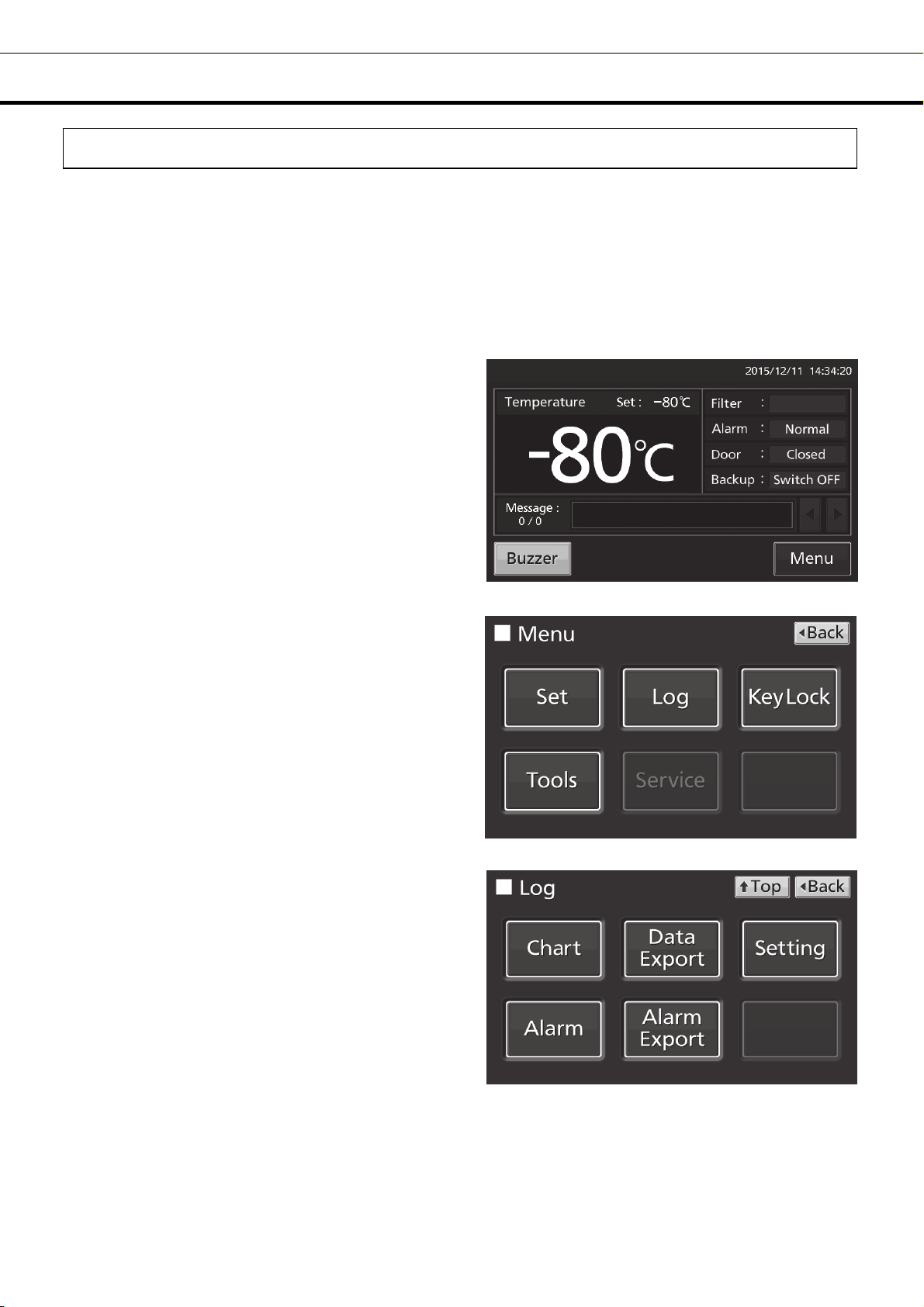
OPERATION/ALARM LOG
Setting log interval
The unit is equipped with a function of saving operation log data (chamber temperature and open/close
state of door).
Note: When the battery switch for power failure alarm is ON, operation log is saved during a power
failure.
Use the following procedure to set the log interval (interval of acquiring the operation log).
1. Press Menu key to lead the Menu screen.
2. Press Log key to lead the Log screen.
3. Press Setting key to lead the Setting screen.
31

OPERATION/ALARM LOG
4. On the Setting screen, input Log Interval. Press
Apply key to save the input value. The display
returns to the Log screen.
Settable range: 2 minutes~30 minutes.
Factory setting: 6 minutes.
Note: Only an even number can be inputted.
When inputting an odd number and when pressing
OK key in the numeric input window, it changes to
an even number which is 1 smaller than that.
Note: It is possible to register 8-digit alphanumeric
characters as the Unique ID. Refer to page 37.
Note: Relation between log interval and the estimated amount of data that can be saved
Log interval=2 minutes: Approx. 46 days
Log interval=6 minutes: Approx. 135 days
Log interval=30 minutes: Approx. 664 days
When saving data more than the above, and the data is overwritten and the old data is delated.
5. Press Top key to return to the Top screen.
Displaying operation log
Operation log saved in the freezer can be displayed graphically on the LCD touch panel.
1. Press Menu key to lead the Menu screen.
2. Press Log key to lead the Log screen.
32

3. Press Chart key to lead the Chart screen.
4. On the Chart screen, input the date (year /
month / day) of the operation log you want to
display graphically.
5. On the Chart screen, by pressing Show key after
pressing the item you want to display graphically,
the graph of each operation log is displayed.
• Actual Temp.:
Chamber temperature log graph
(Go to procedure 6)
• Door Opening:
Open/close state of door log graph
(Go to procedure 7)
33

OPERATION/ALARM LOG
6. Actual Temp. log graph is displayed.
• Press Back key to return to the Chart screen.
• Press Top key to return to the Top screen.
7. Door Opening log graph is displayed.
• Press Back key to return to the Chart screen.
• Press Top key to return to the Top screen.
*When exporting operation log data, without pressing the Export key, follow the procedure on page 35~37.
When pressing Export key by mistake, press the Back key to return to the previous screen.
Note: The error of about 1 minute may be observed during a month. Refer to page 43 for the procedure
of setting time.
To previous day To next day
To previous day
To next day
Export key*
To Door Opening log
To Actual Temp. log
Export key*
34

Exporting operation log
Operation log data saved in the freezer can be exported in CSV format to the USB memory inserted into
the USB port.
1. Insert the USB memory into the USB port.
Note: It is not possible to use a USB memory with security functions that requires entering password.
2. Press Menu key to lead the Menu screen.
3. Press Log key to lead the Log screen.
4. Press Data Export key to lead the Export
screen.
35

OPERATION/ALARM LOG
5. On the Export screen, select the time period you
want to export.
• To export the saved operation log data over the
entire period, press All radio button.
• To export the operation log data of a specified
date, press 1 Day radio button and input the date
(year / month / day) of the operation log data you
want to export.
Note: The error of about 1 minute may be
observed during a month. Refer to page 43 for the
procedure of setting time.
6. On the Export screen, select the type of
operation log data you want to export.
• To export all types of operation log data, press All
Ch key.
• To export only operation log data you want to
export, select operation log data you want to export,
and then press Selected Ch key.
• Actual Temp.: Chamber temperature log data
• Door Opening: Open/close state of outer door log
data
Note: When no USB memory is inserted into
the USB port, Notice dialog box is displayed.
Press OK key, and then insert a USB memory
into the USB port.
36

Note: When the specified operation log data
does not exist, Notice dialog box is displayed.
Press OK key, and then re-specified according
to procedure 4 and 5.
7. When the export is complete, Information
dialog box is displayed. Press OK key.
Note: Even after the export of operation log
data is complete, operation log data saved in
the unit are not deleted.
8. Remove the USB memory from the USB port.
Note:
• The log folder is created in the USB memory, and the exported file is saved in it in CSV format. The
exported file name is in date (8 digits) - type of data format.
(e.g.) When exporting all types of data using All (from Oct. 1st, 2015 to Jan. 1st, 2016):
20151001-20160101_AllCh.csv
20151001-20160101_Door.csv
(e.g.) When exporting Actual Temp. using 1 Day (Jan. 1st, 2016):
20160101_Temp.csv
• On the beginning of the exported file, product name (“MDF-DU900V”) is written. However when the
Unique ID is registered (refer to page 32), product name and Unique ID (8-digit) are written.
(e.g.) When “RoomA001” is set as the Unique ID of MDF-DU900V:
MDF-DU900V, RoomA001
9. Press Top key to return to the Top screen.
37
OPERATION/ALARM LOG
Displaying alarm log
The unit is equipped with a function of saving alarm log data (Max. 256 logs).
Note:
• When saving alarm logs more than 257, the oldest alarm log is deleted, and then overwritten.
• When the battery switch for power failure alarm is ON, operation log is saved during a power failure.
Alarm log saved in the freezer can be displayed graphically on the LCD touch panel.
1. Press Menu key to lead the Menu screen.
2. Press Log key to lead the Log screen.
3. Press Alarm key to lead the Alarm screen.
38

4. On the Alarm screen, the newest 7 days’ alarm
logs (containing that day) are displayed.
Note: When the number of applicable alarm log is
6 or more, by pressing the top (▲) or the bottom
(▼) log, the log table currently displayed scrolls
and hidden alarm logs can be seen.
• Press Back key to return to the Log screen.
• Press Top key to return to the Top screen.
5. On the Alarm screen, by inputting days into the
Last XX Days input box, alarm logs for specified
days (containing that day) are displayed.
Settable range: 1 day~45 days.
Note: The error of about 1 minute may be
observed during 1 month. Refer to page 43 for the
procedure of setting time.
• Press Back key to return to the Log screen.
• Press Top key to return to the Top screen.
●On the Alarm screen of procedure 4 or 5, alarm log data can be exported in CSV format to the USB
memory inserted into the USB port.
6. Insert the USB memory into the USB port.
Note: It is not possible to use a USB memory with security functions that requires entering password.
7. Press Export key.
8. When the export is complete, Information dialog
box is displayed. Press OK key. Refer to page 41
and 42 for the details about abnormal export or
exported file name.
9. Press Top key to return to the Top screen.
39

OPERATION/ALARM LOG
Exporting alarm log
It is possible to export saved alarm log data to a USB memory inserted in the USB port by CSV format.
1. Insert a USB memory in the USB port.
Note: It is not possible to use a USB memory with security functions that requires entering password.
2. Press Menu key to lead the Menu screen.
3. Press Log key to lead the Log screen.
4. Press Alarm Export key to lead Alarm Export
screen.
40

5. On the Alarm Export screen, select the period to
export.
• To export the saved alarm log data over the
entire period, press All radio button.
• To export the alarm log data for the specified
days (The newest period containing that day),
press Last XX Days radio button and input days.
Settable range: 1 day~45 days.
Note: The error of about 1 minute may be
observed during 1 month. Refer to page 43 for
the procedure of setting time.
6. Press Export key.
Note:
• When USB memory is not inserted in the USB
port, Notice dialog box is displayed. Press OK
key and insert an USB memory into the USB
port.
• When alarm log data does not exist in the
specified days, Notice dialog box is displayed.
Press OK key and specify days again as shown
in the procedure 5.
41

OPERATION/ALARM LOG
7. Even after completion the export of alarm log
data, Information dialog box is displayed. Press
OK key.
Note: After completing the export of alarm log
data, alarm log data saved at unit is not deleted.
8. Remove a USB memory from the USB port.
Note: A log folder is created in a USB memory, and an exported data file is saved in the log folder by
CSV format.
Exported file name; The first date during exported period (8 digits) + the last date (8 digits) + AlarmLog
Example) When exporting alarm log data for 7 days on January 7, 2016;
20160101-20160107_AlarmLog.csv
9. Press Top key to return to the Top screen.
42

OTHER PARAMETERS
Setting date and time
1. Press Menu key to lead the Menu screen.
2. Press Tools key to lead the Tools screen.
3. Press Date & Time key to lead the Date &
Time screen.
4. On the Date & Time screen, input the present
date and time. Press Apply key to save the input
value. The display returns to the Tools screen.
Note:
• 24-hour clock.
• It is recommended to set the time periodically
since the error of about 1 minute may be observed
during a month.
5. Press Top key to return to the Top screen.
43

OTHER PARAMETERS
Setting brightness and sleep
1. Press Menu key to lead the Menu screen.
2. Press Tools key to lead the Tools screen.
3. Press Brightness/Sleep key to lead the
Brightness/Sleep screen.
4. On the Brightness/Sleep screen, each setting of
brightness and sleep is available. Press Apply key
to save the input value and setup. The display
returns to the Tools screen.
44

●Each setting
• Brightness(Active):
Brightness of LCD touch panel of the usual state. Adjust Brightness(Active) slide bar or input set value
into the Brightness(Active) input box. Settable range: 50~100, factory setting: 80.
• Sleep:
The function is that the brightness of LCD touch panel is lowered to save electricity, when there is no key
operation during set time.
By holding the Sleep slide key and sliding it right, the Sleep function is turned to ON. Input the set value
of time to change the Sleep state. Settable range: 1 minute~5 minutes, factory setting: 2 minutes.
Note: It is not possible to operate any key in the Sleep state. By touching the LCD touch panel, the Sleep
state is released and the LCD touch panel returns to the usual state. Under this condition, key operations
are available.
• Brightness(Sleep):
Brightness of LCD touch panel of the Sleep state. Adjust Brightness(Sleep) slide bar or input set value
into the Brightness(Sleep) input box. Settable range: 0~50, factory setting: 20.
5. Press Top key to return to the Top screen.
45

OPERATION MONITOR SYSTEM
This unit has the operation monitor system. It is the function to detect and inform some hard operating
conditions that leaving the unit operating may cause a failure. The table 2 shows the information of the
operation monitor system.
Table 2 Information of the operation monitor system
Information Status
Abnormal
ambient
temperature
Overload
operation
When the ambient
temp. is over approx.
o
35
C or lower than
approx. 0
When the chamber
temp. does not reach
the set temp. for
approx. 5 days or
more.
o
C.
Status1:
Ambient Temp Abnormal.
Status3:
Cooling Circuits
Overload.
Message
display field
Note:
• The operation monitor system is not the alarm function. Buzzer, remote alarm and safety operation are
not activated.
• “Status 2” does not exist.
• When the above remedy results in the following situations, contact our sales representative or agent.
The message does not disappear.
The message is displayed repeatedly.
Other situations.
If this status
continues
The cooling
performance and/or the
durability of the
refrigerating circuit may
get worse.
Recheck air-conditioning of
installed site.
* The message disappears
when the ambient temp.
returns to within allowable
range. (approx. 0
(1) Do not put a large amount
of contents to cryopreserve at
a time.
(2) Reduce the opening
frequency of the door.
(3) Make sure that there is no
leak around the door or the
inner lid.
(4) Set the chamber temp. to
o
-80
C or higher.
* The message disappears
when the chamber temp.
reaches the set temp. after
resolving the overload
operation by the above
remedy.
Remedy
o
C~35 oC)
46

ALARMS, SAFETY, AND SELF-DIAGNOSIS
This unit has the alarms, safety functions, and self-diagnostic functions of the table 3.
Table 3 Alarms and safety function list
LCD touch panel
Alarm & safety Situation
Message
display field
Warning:
High Temp.
(After alarm delay
time has elapsed.)
Warning:
Low Temp.
(After alarm delay
time has elapsed.)
Warning:
Power Failure
High Alarm
Low Alarm
Power failure
alarm
If the chamber temperature exceeds
the set temp. + the set value of High
Alarm.
(Settable range: +5
If the chamber temperature falls
below the set temp. - the set value of
Low Alarm.
(Settable range: +5
The battery switch for power failure
alarm is ON, and under any of the
following conditions.
o
C~+40 oC)
o
C~+40 oC)
• During a power failure
• Power switch is OFF
• Power supply cord is disconnected.
Door alarm When door is open. ―
Other
• Alarm display
(During alarm delay)
“Alarm” is displayed
alternately in normal
characters and reverse video
(After alarm delay)
“Warning” is displayed
alternately in normal
characters and reverse video
• Present temperature
display field
Present temperature blinks.
• LCD touch panel
Turned OFF. By touching the
LCD touch panel, it lights in
the set brightness for 5
seconds.
• Door display
“Open” is displayed
alternately in normal
characters and reverse video
Buzzer
Intermittent tone
(After alarm
delay time has
elapsed.)
Intermittent tone ON
Intermittent tone
(After door delay
time has
elapsed.)
Remote
alarm
ON
(After
alarm
delay time
has
elapsed.)
―
Filter alarm
Auto-return
Battery for power
failure alarm
replacement
Battery for backup
cooling kit
replacement
When the excessive dust is
accumulated on the condenser filter.
On screens other than the Top
screen, there is no key operation for
approx. 90 s.
(When the sleep function is ON)
After sleep function is turned ON,
there is no alarm/error and key
operation for approx. 90 s.
When the cumulative operating time
exceeds 3 years.
When 3 years passed after installing
backup cooling kit.
―
― (Return to the “Top screen”.) ― ―
Warning:
Exchange
a Main Battery.
Warning:
Exchange
a Backup Battery.
• Filter alarm indicator
Indicator is lit (orange).
― ― ―
― ― ―
Intermittent tone
Note:
• Settable range of the alarm delay time: 0 minute~15 minutes (refer to page 29).
• After turning ON the unit to start operation, only the first time, alarm delay is activated until the chamber
temperature is cooled to the High Alarm set temperature or less (Namely, the alarm display does not
change to “Warning”, buzzer does not sound and remote alarm is not activated).
• Settable range of the door delay time: 0 minute~15 minutes (refer to page 29).
• The battery for power failure alarm and for backup cooling kit are articles for consumption. It is
recommended that both batteries will be replaced about every 3 years. Contact our sales representative
or agent at the time of replacement of the battery.
―
47

ALARMS, SAFETY, AND SELF-DIAGNOSIS
Table 3 Alarms & safety function list
LCD touch panel
Alarm & safety Situation
If the thermal sensor is
disconnected.
If the thermal sensor is
short-circuited.
If the cascade sensor is
disconnected.
If the cascade sensor is
Sensor abnormality
Battery switch check
Condenser temp
abnormality
Communication
error
short circuited.
If the filter sensor is
disconnected.
If the filter sensor is
short-circuited.
If the ambient tem. sensor
is disconnected.
If the ambient tem. sensor
is short-circuited.
When the battery switch
for power failure alarm is
OFF.
When the fan motor for
cooling the compressor
fails.
(If the temperature of the
filter sensor is 52
higher.)
When communication
between LCD touch
panel and control
substrate is died out or
unstable.
o
C or
●When “disconnecting/short-circuit of the thermal sensor” and “condenser temp. abnormality” are
activated at the same time, safety operation of compressor OFF is prioritized.
Message display field Alarm display
Err01:
Temperature Sensor Open.
Err02:
Temperature Sensor Short.
Err03:
Cascade Sensor Open.
Err04:
Cascade Sensor Short.
Err05:
Filter Sensor Open.
Err06:
Filter Sensor Short.
Err07:
Ambient Temp Sensor Open.
Err08:
Ambient Temp Sensor Short.
Err09:
Battery Switch is OFF.
Err10:
Condenser Temp Abnormal.
Err56:
Communication Failure.
“Warning” is
displayed
alternately in
normal
characters and
reverse video.
― ― ― ―
“Warning” is
displayed
alternately in
normal
characters and
reverse video
― ― ― ―
Buzzer
Intermittent
tone
Intermittent
tone
Remote
alarm
ON
ON
Safety
operation
Unit is
continuous
running.
―
―
―
Compressor
OFF
48

●Table 4~5 show the behavior of the alarm (buzzer) and Ring Back function when pressing Buzzer key.
Table 4 In the cases of other than the door alarm.
Remote Alarm setting
ON: Non-interlock
with Buzzer key
OFF: Interlock
with Buzzer key
Note: Resolve the cause of the alarm in reference to page 47~48 because the alarm itself is not
deactivated by pressing Buzzer key.
Table 5 In the cases of the door alarm.
Remote Alarm setting
ON: Non-interlock
with Buzzer key
OFF: Interlock
with Buzzer key
●Table 6 shows the situation after being canceled the High/Low Alarm and recovery from a power failure
with no operation.
Table 6 The situation after being canceled the High/Low Alarm and recovery from a power failure with
no operation
Canceled alarm
Ring Back
setting
ON
OFF OFF
ON ON
OFF OFF OFF
Ring Back
setting
ON
OFF
ON
OFF
Message display field Alarm display
When pressing
Buzzer key
(Alarm is not
canceled)
When pressing
Buzzer key
(Alarm is
canceled)
Buzzer from unit Remote Alarm
When the Ring Back
set time passes
OFF
Buzzer from unit
When the Ring Back
set time passes
OFF
(Alarm is already
LCD touch panel
ON
OFF
canceled)
When pressing
Buzzer key
ON
OFF (Alarm is
not canceled)
Remote Alarm setting
Buzzer
When the Ring Back
set time passes
(Under continuation)
OFF
Remote
alarm
ON
ON
Safety
operation
High Alarm
Low Alarm
Power failure
alarm
Note: By pressing Buzzer key, the alarm display returns to “Normal” and buzzer stops.
―
―
“Alarm” is displayed alternately in
normal characters and reverse video
“Alarm” is displayed alternately in
normal characters and reverse video
Intermittent
Intermittent
tone
tone
― ―
― ―
49

ROUTINE MAINTENANCE
WARNING
Always disconnect the power supply to the unit prior to any repair or maintenance of the unit in
order to prevent electric shock or injury.
Ensure you do not inhale or consume medication or aerosols from around the unit at the time of
maintenance. These may be harmful to your health.
Cleaning of cabinet
• Clean the unit once a month. Regular cleaning keeps the unit looking new.
• Use a dry cloth to wipe off small amounts of dirt on the outside and inside of the unit and all accessories.
If the outside panels are dirty, clean them with a diluted neutral dishwashing detergent (Undiluted
detergent can damage the plastic components. For the dilution, refer to the instruction of the detergent).
After the cleaning with the diluted detergent, always wipe it off with a wet cloth. Then wipe off the cabinet
or accessories with a dry cloth.
• Never pour water onto or into the unit. Doing so can damage the electric insulation and cause failure.
• The compressor and other mechanical parts are completely sealed. This unit requires absolutely no
lubrication.
Note: Always replace the inner accessories removed for the cleaning to keep the intended performance.
Cleaning of condenser filter
This unit is provided with the filter alarm indicator on the LCD touch panel. Clean the condenser filter
when this indicator is lit. Clean the condenser filter once a month even if the filter alarm indicator is not
on. A dusty condenser filter may cause shorter compressor life as well as the poor cooling.
Clean the condenser filter by the procedure below.
1. Open the grille by pulling it to you as shown in the
figure.
2. Take out the condenser filter.
3. Wash the condenser filter with water.
4. Replace the condenser filter and the grille. (Set the
handle of the condenser filter at the front.)
5. Check that the filter alarm indicator is off in the event
the filter alarm indicator was ON.
Condenser
filter
Grille
WARNING
Do not touch the condenser directly when the filter is removed for cleaning. This may cause injury by
hot surface.
50

Defrosting of chamber
The frost is built at the upper portion of the chamber and inner door. The excessive frost possibly make
some gap between the cabinet and the magnetic door gasket, which may cause poor cooling. Remove
the frost on the inner door with a scraper enclosed with the unit. Following shows the procedure for
removing the chamber frost.
Note: For removing the frost, do not use a tool with sharp edge such as a knife or a screw driver.
1. Turn off the backup cooling kit if it is installed.
2. Take out and transfer all the contents to another freezer or a container which is refrigerated by liquid
carbon dioxide or dry ice.
3. Turn off the power switch and battery switch of the
freezer.
4. Open the outer door and inner door. Remove the
inner door by lifting up as shown in the figure.
5. Leave the freezer as it is.
6. The water accumulated on the bottom of the
chamber should be wiped up with a dry cloth.
7. After cleaning the chamber and inner door, replace
the inner door and start up the unit according to the
procedure on page 17.
8. Put back the articles into the sufficiently cooled
freezer compartment.
9. Turn on the backup cooling kit if it is installed.
WARNING
Always mount and/or remove the inner door by two people. The work by oneself may cause injury
from falling.
Always wear gloves when mounting and/or removing the inner door to prevent injury.
51

ROUTINE MAINTENANCE
Cleaning of air intake port
To open the outer door, the cap on the left side is turned counterclockwise to take the air. Therefore, the
frost is easy to be settled around the air intake port or in it. Clean the air intake port depending on the
conditions below:
Condition Remedy
When the frost and ice can
be seen in the air intake port.
The outer door cannot be
opened even if the cap on
the air intake port is
removed.
The frost and ice are built in
the chamber.
Remove the frost and ice with the stick for air intake port cleaning.
Remove the frost and ice with the stick for air intake port cleaning.
Remove the frost and ice with the enclosed scraper.
Stick for air intake port cleaning (Accessory)
CAUTION
For removing the frost in the air intake port, do not use a tool with sharp edge such as a knife or a screw
driver.
CALIBRATION
During running operation, the following service works must be performed;
• Perform temperature calibration at least once a year.
For the temperature calibration, contact our sales representative or agent.
52

REPLACEMENT OF WEAR-OUT PARTS
Replacing the battery for power failure alarm
Replace the battery for power failure alarm every 3 years. Contact our sales representative or agent for the
replacement of battery when “Warning: Exchange a Main Battery.” is displayed in the message display
field.
The replacement of the battery for power failure alarm is a paid service.
The alarm function (message display, sound of buzzer and remote alarm) will not operate when the battery for
power failure alarm is flat.
“Warning: Power Failure.” is displayed and the buzzer sounds by the battery for power failure alarm. The
regular replacement of the battery for power failure alarm is important to prevent the rise of chamber
temperature in the case of unexpected situation.
WARNING
«Important» The used battery is a recyclable precious resource. Do not dispose of the
battery. Always follow the procedure for recycling.
The replacement of the battery for power failure alarm
should be executed by a qualified engineer or service
personnel only.
alarm involves the risk of electric shock.
The replacement of the battery for power failure
Replacing the battery for backup cooling kit
Replace the battery for backup cooling kit every 3 years. Contact our sales representative or agent for the
replacement of battery when “Warning: Exchange a Backup Battery.” is displayed in the message display
field.
The replacement of the battery for backup cooling kit is a paid service.
The backup cooling kit will not operate when the battery for backup cooling kit is flat.
When the chamber temperature rises, the backup cooling kit is activated by the battery for backup cooling kit
even during a power failure. The regular replacement of the battery for backup cooling kit is important to
prevent the rise of chamber temperature in the case of unexpected situation.
WARNING
«Important» The used battery is a recyclable precious resource. Do not dispose of the
battery. Always follow the procedure for recycling.
The replacement of the battery for backup cooling kit should
be executed by a qualified engineer or service personnel
only.
involves the risk of electric shock.
The replacement of the battery for backup cooling kit
53

TROUBLESHOOTING
If the unit malfunctions, check out the following before calling for service.
Malfunction Check/Remedy
The unit does not operate
at all when turning ON the
power switch.
The compressor does not
operate at all when turning
ON the power switch.
(LCD touch panel is turned
ON)
An alarm is activated. □ A little before, the value of the chamber temperature has been
The cooling is poor. □ A large amount of warm contents are put into the chamber.
The outside of the unit is
wet with dew.
Noisy in motor sound or
flowing liquid.
Note:
• If the malfunction is not eliminated after checking the above items, or the malfunction is not shown in the
above table, contact our sales representative or agent.
• Keep an electric product which emits an electromagnetic wave away from this unit. A noise from an
electromagnetic wave may cause malfunction to this unit.
□ The unit is not connected to the power supply.
□ During a power failure.
□ The circuit breaker is activated.
□ The capacity of power supply is not sufficient. When the capacity of
power supply is not sufficient to start the compressor, compressor may
not start.
changed significantly.
□ The door had been left open for a long time.
□ Some warm contents are put into the chamber.
*In the above cases, the alarm is canceled with no operation.
□ A large amount of frost is built on the inside wall of the chamber.
□ The door is often opened.
□ The set value of the chamber temperature is lower than -86
temperature settable range is between -50
temperature control range is between -50
□ The ambient temperature is higher than 30
temperature is between 5
□ The unit is in the direct sunlight.
□ There is no more than 10 cm clearance around the unit.
□ The grille or the exhaust air bent is blocked by something.
□ The unit is not installed horizontally.
In case of sultriness or bad location, the exterior of the unit may be wet
with dew. Under a high humidity environment, the cold exterior of the
unit condenses the moisture in the air, so that it is not malfunction. Wipe
the dew with a dry cloth.
On the characteristics of the cooling circuit, the sound of motor or
flowing refrigerant may be heard during operation. Especially a few
hours after starting operation, the sound of compressor or flowing
refrigerant may be loud, however it is a normal operation.
o
C~30 oC.
o
C~-90 oC. However, the
o
C~-86 oC.
o
C. The allowable ambient
o
C. The
54

DISPOSAL OF UNIT
請回收
Before disposing the unit with biohazardous danger, decontaminate the unit to the extent possible by the
user.
WARNING
If the unit is to be stored unused in an unsupervised area for an extended period ensure that children
do not have access and doors cannot be closed completely.
The disposal of the unit should be accomplished by appropriate personnel. Always remove
doors to prevent accidents such as suffocation.
Recycle of battery
■ Label indication is obliged to comply with Japanese battery regulation.
廢電池
■ Label indication is obliged to comply with Taiwanese battery regulation.
55

DISPOSAL OF UNIT
(English)
Disposal of Old Equipment and Batteries
Only for European Union and countries with recycling systems
These symbols on the products, packaging, and/or accompanying documents mean that used electrical
and electronic products and batteries must not be mixed with general household waste.
For proper treatment, recovery and recycling of old products and used batteries, please take them to
applicable collection points in accordance with your national legislation.
By disposing of them correctly, you will help to save valuable resources and prevent any potential
negative effects on human health and the environment.
For more information about collection and recycling, please contact your local municipality.
Penalties may be applicable for incorrect disposal of this waste, in accordance with national legislation.
Note for the battery symbol (bottom symbol):
This symbol might be used in combination with a chemical symbol. In this case it complies with the
requirement set by the Directive for the chemical involved.
(German)
Entsorgung von Altgeräten und Batterien
Nur für die Europäische Union und Länder mit Recyclingsystemen
Dieses Symbol, auf den Produkten, der Verpackung und/oder den Begleitdokumenten, bedeutet, dass
gebrauchte elektrische und elektronische Produkte sowie Batterien nicht in den allgemeinen Hausmüll
gegeben werden dürfen.
Bitte führen Sie alte Produkte und verbrauchte Batterien zur Behandlung, Aufarbeitung bzw. zum
Recycling gemäß den gesetzlichen Bestimmungen den zuständigen Sammelpunkten zu.
in Deutschland gesetzlich zur Rückgabe von Altbatterien an einer geeigneten Annahmestelle verpflichtet.
Batterien können im Handelsgeschäft unentgeltlich zurückgegeben werden.
Indem Sie diese Produkte und Batterien ordnungsgemäß entsorgen, helfen Sie dabei, wertvolle
Ressourcen zu schützen und eventuelle negative Auswirkungen auf die menschliche Gesundheit und die
Umwelt zu vermeiden.
Für mehr Informationen zu Sammlung und Recycling, wenden Sie sich bitte an Ihren örtlichen
Abfallentsorgungsdienstleister.
Gemäß Landesvorschriften können wegen nicht ordnungsgemäßer Entsorgung dieses Abfalls Strafgelder
verhängt werden.
Hinweis für das Batteriesymbol (Symbol unten):
Dieses Symbol kann in Kombination mit einem chemischen Symbol abgebildet sein. In diesem Fall erfolgt
dieses auf Grund der Anforderungen derjenigen Richtlinien, die für die betreffende Chemikalie erlassen
wurden.
Endnutzer sind
56

DISPOSAL OF UNIT
(French)
L’élimination des équipements et des batteries usagés
Applicable uniquement dans les pays membres de l’Union européenne et les pays
disposant de systèmes de recyclage.
Apposé sur le produit lui-même, sur son emballage, ou figurant dans la documentation qui l’accompagne,
ce pictogramme indique que les piles, appareils électriques et électroniques usagés, doivent être
séparées des ordures ménagères.
Afin de permettre le traitement, la valorisation et le recyclage adéquats des piles et des appareils usagés,
veuillez les porter à l’un des points de collecte prévus, conformément à la législation nationale en vigueur.
En les éliminant conformément à la réglementation en vigueur, vous contribuez à éviter le gaspillage de
ressources précieuses ainsi qu’à protéger la santé humaine et l’environnement.
Pour de plus amples renseignements sur la collecte et le recyclage, veuillez vous renseigner auprès des
collectivités locales.
Le non-respect de la réglementation relative à l’élimination des déchets est passible d’une peine
d’amende.
Note relative au pictogramme à apposer sur les piles (pictogramme du bas) :
Si ce pictogramme est combiné avec un symbole chimique, il répond également aux exigences posées
par la Directive relative au produit chimique concerné.
(Spanish)
Eliminación de Aparatos Viejos y de Pilas y Baterías
Solamente para la Unión Europea y países con sistemas de reciclado.
Estos símbolos en los productos, su embalaje o en los documentos que los acompañen significan que
los productos eléctricos y electrónicos y pilas y baterías usadas no deben mezclarse con los residuos
domésticos.
Para el adecuado tratamiento, recuperación y reciclaje de los productos viejos y pilas y baterías usadas
llévelos a los puntos de recogida de acuerdo con su legislación nacional.
obligados a entregar las pilas en los correspondientes puntos de recogida. En cualquier caso, la entrega
por los usuarios será sin coste alguno para éstos.El coste de la gestión medioambiental de los residuos
de pilas, acumuladores y baterías está incluido en el precio de venta.
Si los elimina correctamente ayudará a preservar valuosos recursos y evitará potenciales efectos
negativos sobre la salud de las personas y sobre el medio ambiente.
Para más información sobre la recogida u reciclaje, por favor contacte con su ayuntamiento.
Puede haber sanciones por una incorrecta eliminación de este residuo, de acuerdo con la legislación
nacional.
Nota para el símbolo de pilas y baterías (símbolo debajo):
Este símbolo puede usarse en combinación con el símbolo químico. En este caso, cumple con los
requisitos de la Directiva del producto químico indicado.
En España, los usuarios están
57

DISPOSAL OF UNIT
(Portuguese)
Eliminação de Equipamentos Usados e Baterias
Apenas para a União Europeia e países com sistemas de reciclagem
Estes símbolos nos produtos, embalagens, e/ou documentos que os acompanham indicam que os
produtos elétricos e eletrónicos e as baterias usados não podem ser misturados com os resíduos
urbanos indiferenciados.
Para um tratamento adequado, reutilização e reciclagem de produtos e baterias usados, solicitamos que
os coloque em pontos de recolha próprios, em conformidade com a respetiva legislação nacional.
Ao eliminar estes produtos corretamente estará a ajudar a poupar recursos valiosos e a prevenir
quaisquer potenciais efeitos negativos sobre o ambiente e a saúde humana.
Para mais informações acerca da recolha e reciclagem, por favor contacte a sua autarquia local.
De acordo com a legislação nacional podem ser aplicadas contraordenações pela eliminação incorreta
destes resíduos.
Nota para o símbolo da bateria (símbolo na parte inferior):
Este símbolo pode ser utilizado conjuntamente com um símbolo químico. Neste caso estará em
conformidade com o estabelecido na Diretiva referente aos produtos químicos em causa.
(Italian)
Smaltimento di vecchie apparecchiature e batterie usate
Solo per Unione Europea e Nazioni con sistemi di raccolta e smaltimento
Questi simboli sui prodotti, sull’imballaggio e/o sulle documentazioni o manuali accompagnanti i prodotti
indicano che i prodotti elettrici, elettronici e le batterie usate non devono essere buttati nei rifiuti domestici
generici.
Per un trattamento adeguato , recupero e riciclaggio di vecchi prodotti e batterie usate vi invitiamo a
portarli negli appositi punti di raccolta secondo la legislazione vigente nel vostro paese.
Con uno smaltimento corretto, contribuirete a salvare importanti risorse e ad evitare i potenziali effetti
negativi sulla salute umana e sull’ambiente.
Per ulteriori informazioni su raccolta e riciclaggio, vi invitiamo a contattare il vostro comune.
Lo smaltimento non corretto di questi rifiuti potrebbe comportare sanzioni in accordo con la legislazione
nazionale.
Note per il simbolo batterie (simbolo sotto):
Questo simbolo può essere usato in combinazione con un simbolo chimico. In questo caso è conforme ai
requisiti indicati dalla Direttiva per il prodotto chimico in questione.
58

DISPOSAL OF UNIT
(Dutch)
Het ontdoen van oude apparatuur en batterijen.
Enkel voor de Europese Unie en landen met recycle systemen.
Deze symbolen op de producten, verpakkingen en/of begeleidende documenten betekenen dat gebruikte
elektrische en elektronische producten en batterijen niet samen mogen worden weggegooid met de rest
van het huishoudelijk afval.
Voor een juiste verwerking, hergebruik en recycling van oude producten en batterijen, gelieve deze in te
leveren bij de desbetreffende inleverpunten in overeenstemming met uw nationale wetgeving.
Door ze op de juiste wijze weg te gooien, helpt u mee met het besparen van kostbare hulpbronnen en
voorkomt u potentiële negatieve effecten op de volksgezondheid en het milieu.
Voor meer informatie over inzameling en recycling kunt u contact opnemen met uw plaatselijke
gemeente.
Afhankelijk van uw nationale wetgeving kunnen er boetes worden opgelegd bij het onjuist weggooien van
dit soort afval.
Let op: het batterij symbool (Onderstaand symbool).
Dit symbool kan in combinatie met een chemisch symbool gebruikt worden. In dit geval volstaan de eisen,
die zijn vastgesteld in de richtlijnen van de desbetreffende chemische stof.
(Swedish)
Avfallshantering av produkter och batterier
Endast för Europeiska Unionen och länder med återvinningssystem
Dessa symboler på produkter, förpackningar och/eller medföljande dokument betyder att förbrukade
elektriska och elektroniska produkter och batterier inte får blandas med vanliga hushållssopor.
För att gamla produkter och använda batterier ska hanteras och återvinnas på rätt sätt ska dom lämnas
till passande uppsamlingsställe i enlighet med nationella bestämmelser.
Genom att ta göra det korrekt hjälper du till att spara värdefulla resurser och förhindrar eventuella
negativa effekter på människors hälsa och på miljön.
För mer information om insamling och återvinning kontakta din kommun.
Olämplig avfallshantering kan beläggas med böter i enlighet med nationella bestämmelser.
Notering till batterisymbolen (nedanför):
Denna symbol kan användas i kombination med en kemisk symbol. I detta fall uppfyller den de krav som
ställs i direktivet för den aktuella kemikalien.
59

TEMPERATURE RECORDER (OPTION)
The chamber temperature can be recorded and checked by installing an optional temperature recorder
MTR-85H or MTR-G85C.
Contact our sales representative or agent for the purchase of temperature recorder.
Main specifications of temperature recorder
MTR-85H MTR-G85C
Recording
range
Feed speed of
recorder chart
Record chart Strip type Circular type
Power source Dry cell Supplied from the unit
For the installation of temperature recorder MTR-85H, an optional recorder fixing MDF-S3085 and recorder
sensor cover MTR-DU700SF is necessary.
For the installation of temperature recorder MTR-G85C, an optional recorder sensor cover MTR-DU700SF is
necessary.
o
-100
C~+50 oC -100
2-month/batch
o
C~+40 oC
1-day/1 turn,
7-day/1 turn
32-day/1 turn
changeable
SMALL INNER DOOR (OPTION)
For MDF-DU900V, the small inner door (MDF-9ID) is available as an optional component. The small
inner door is suitable for standard shelf location.
For the installation, contact our sales representative or agent.
Note:
The cooling performance on the page 64 cannot be obtained when the small inner door (MDF-9ID) is
installed.
Cooling performance : -82
An optional inventory rack IR-224U cannot be used when the small inner door is installed.
o
C at the center of the chamber (ambient temperature; 30oC, no load)
60

INVENTORY RACK (OPTION)
The optional inventory racks (IR-220U, IR-224U) are useful to store the precious materials in the chamber
effectively. When the racks are used, it is necessary to adjust the height of the shelves. Set the shelf
stopper as shown in the figure below.
<Attachment of shelf stopper>
1. Insert the upper side.
2. Push-in the lower side
IR-220U
IR-224U
NOTE:
Only inventory rack IR-220U can be applied
when the independent inner door (MDF-9ID)
is installed.
Shelf support
Shelf stopper
No. 4 under second screw from the top
(There is a mark which hollowed at the
shelf support front side.)
No. 3 under fifth screw from the top
(There is a mark which hollowed at the
shelf support front side.)
No. 2 under third screw from the top
(There is a mark which hollowed at the
shelf support front side.)
WARNING
Fix the shelf supports and shelves securely. And store the inventory racks securely.
Incomplete installation may cause injury or damage.
61
BACKUP COOLING KIT (OPTION)
By installing an optional backup cooling kit MDF-UB6B and a liquid CO
the chamber prevent to rise the chamber temperature for a few hours, even when this unit stops
operation by a power failure and so on.
Contact our sales representative or agent for the purchase of backup cooling kit.
cylinder, liquid CO2 injection into
2
WARNING
As with any equipment that uses CO
gas, there is a likelihood of oxygen depletion in the vicinity
2
of the equipment. It is important that you assess the work site to endure there is suitable and
sufficient ventilation. If restricted ventilation is suspected, then other methods of ensuring a safe
environment must be considered. These may include atmosphere monitoring and warning
devices.
The injection set temperature of the backup cooling kit can be set by the temperature setting knob.
Since the control method of injection is ON/OFF type, the actual injection temperature deviates from the
injection set temperature.
Note:
• Set the injection set temperature of the backup cooling kit to 10
Otherwise, continuous injection of liquid CO
may reduce the retention time of liquid CO2 cylinder.
2
• When the injection set temperature of the backup cooling kit is -70
ON: -65
o
C~-67 oC, OFF: -74 oC~-75 oC.
o
C higher than the set temperature.
o
C;
The behavior of the backup cooling kit
Backup
power switch
Backup
display
(Page 11)
Condition of the
backup cooling kit
Chamber temperature Liquid CO
2
ON Switch ON Ready to inject
Not ready to inject
OFF Switch OFF
(Not ready to activate
the backup test switch)
Less than the injection set
temperature of the backup
cooling kit.
The injection set temperature
of the backup cooling kit or
higher.
Less than the injection set
temperature of the backup
cooling kit.
The injection set temperature
of the backup cooling kit or
higher.
Does not inject
Injects
Does not inject
62

SPECIFICATIONS
Product name
Medical purpose
External dimensions
Internal dimensions
Effective capacity
Exterior
Interior
Outer door
Inner door ABS resin panel with stainless frame, 2 doors
Shelf
Access port
Insulation
Compressor
Evaporator
Condenser
Refrigerant High stage side; R-404A, Low stage side; R-508A
Temperature controller
Temperature display
Thermal sensor
Alarm
Remote alarm contact
Battery
Weight
Accessories
Optional component
* For the data acquisition system MTR-5000 user only. Contact our sales representative or agent for purchase.
Note:
• Design or specifications will be subject to change without notice.
• Refer to the updated catalog when ordering an optional component.
High stage side; Cascade type, Low stage side; Tube on sheet type
High stage side; Fin and tube type, Low stage side; Shell and tube type
High Alarm, Low Alarm, Power failure alarm, Door alarm, Filter alarm
Temperature recorder (MTR-85H, MTR-G85C)
Recorder sensor cover (MTR-DU700SF)
Recorder fixing (MDF-S3085; MTR-85H)
Backup cooling kit (MDF-UB6B); For Liquid CO
Inventory rack (IR-224U, IR-220U)
Small inner door (MDF-9ID)
Interface board (MTR-L03)*; For LAN
Interface board (MTR-480)*; For RS-232C/RS-485
Inner diameter: 17 mm, 2 locations (back, bottom)
Vacuum insulation panel + Rigid polyurethane foamed-in place
High stage side; Hermetic type, Output; 1100 W
Low stage side; Hermetic type, Output; 1100 W
Lead storage battery, DC 6 V, 7200 mAh, Auto-recharge
2 keys, 1 scraper, 1 stick for air intake port cleaning
Ultra-Low Temperature Freezer
MDF-DU900V
Storage of cells, organs, DNAs, plasma.
W1150 mm x D870 mm x H1990 mm
W1010 mm x D600 mm x H1400 mm
845 L
Painted steel
Painted steel
Painted steel
Stainless steel, 3 shelves (adjustable)
Inner dimension; W988 mm x D533 mm
Load; 50 kg/shelf
Microcomputer control system
LCD Digital display
Platinum resistance (Pt 1000 Ω)
Allowable contact capacity: DC 30 V, 2 A
372 kg
2
63

PERFORMANCE
Product name
Model number
o
C at the center of the chamber (ambient temperature; 30 oC, no load)*
Cooling performance
Temperature settable range
Temperature control range
Rated voltage
Rated frequency
Rated power consumption
Noise level
Maximum pressure
* Maximum cooling performance.
The chamber temperature can be reached at -86
Note:
• Specifications will be subject to change without notice.
• The unit with CE mark complies with EU directives.
-86
-50
o
o
Ultra-Low Temperature Freezer
MDF-DU900V
MDF-DU900V-PE
o
C to -90 oC
-50
C to -86 oC (ambient temperature; 30 oC, no load)
AC 230 V/240 V
50 Hz
980 W/1045 W
52 dB [A] (background noise; 20 dB)
2900 kPa
C at ambient temperature 30 oC with no load.
64

CAUTION
Please fill in this form before servicing.
Hand over this form to the service engineer to keep for his and your safety.
Safety check sheet
1. Freezer contents :
Risk of infection:
Risk of toxicity:
Risk from radioactive sources:
(List all potentially hazardous materials that have been stored in this unit.)
Notes :
2.
Contamination of the unit
Unit interior
No contamination
Decontaminated
Contaminated
Others:
3. Instructions for safe repair/maintenance/disposal of the unit
a) The unit is safe to work on
b) There is some danger (see below)
Procedure to be adhered to in order to reduce safety risk indicated in b) below.
Date :
Signature :
Address, Division :
Telephone :
□Yes □No
□Yes □No
□Yes □No
□Yes □No
□Yes □No
□Yes □No
□Yes □No
□Yes □No
Product name: Model: Serial number: Date of installation:
Ultra-low temperature MDF-
freezer
Please decontaminate the unit yourself before calling the service engineer.
65

Original Operating Instructions
< EU countries only >
0123
Nijverheidsweg 120 4879 AZ Etten Leur, The Netherlands
1-1-1 Sakada, Oizumi-machi, Ora-gun, Gunma 370-0596, Japan
© PHC Corporation 2018
Printed in Japan
LDCL031100-0
S0418-0
2018.04.01
 Loading...