


Operating Instructions
Ultra-Low Temperature Freezer
MDF-DU702VH
MDF-DU502VH
MDF-DU702VH
Please read the operating instructions carefully before using this product, and keep the operating
instructions for future use.
See page 58 for all model numbers.

CONTENTS
INTRODUCTION ········································································· 3
PRECAUTIONS FOR SAFE OPERATION ········································· 4
SYMBOLS ON UNIT ····································································· 9
ENVIRONMENTAL CONDITIONS ··················································· 9
FREEZER COMPONENTS
Main body ············································································ 10
LCD touch panel ··································································· 12
Remote alarm terminal ··························································· 14
Air intake port (Manual) ·························································· 14
INSTALLATION SITE ·································································· 15
INSTALLATION ········································································· 16
START-UP PROCEDURE ··························································· 18
DURING/AFTER POWER FAILURE
Operation during power failure ················································· 19
Operation after recovery from power failure ································· 19
BASIC OPERATION ON LCD TOUCH PANEL ································· 20
BASIC PARAMETERS
How to input numerical value and alphanumeric character ·············· 21
Setting Temperature, High Alarm and Low Alarm ························· 23
Setting operation control mode ················································· 24
Setting key lock ···································································· 25
Removing key lock ································································· 28
ALARM PARAMETERS ······························································ 29
OPERATION/ALARM LOG
Setting log interval ································································· 31
Displaying operation log ·························································· 32
Exporting operation log ·························································· 35
Displaying alarm log ······························································· 38
Exporting alarm log ································································ 40
OTHER PARAMETERS
Setting date and time······························································ 43
Setting brightness and sleep ···················································· 44
ALARMS AND SELF-DIAGNOSIS ················································· 46
ROUTINE MAINTENANCE
Cleaning the exterior, interior, and accessories ···························· 49
Cleaning of air intake port (Manual) ··········································· 49
Cleaning of condenser filter ····················································· 50
Defrosting of chamber ··························································· 51
CALIBRATION ·········································································· 51
REPLACEMENT OF WORN-OUT PARTS
Replacing the battery for power failure alarm ······························· 52
Replacing the battery for backup cooling kit ································ 52
TROUBLESHOOTING ································································ 53
DISPOSAL OF UNIT ·································································· 54
Recycle of battery ································································· 54
OPTIONAL COMPONENTS
Temperature recorder ···························································· 55
Small inner doors ·································································· 55
Inventory rack ······································································ 55
Back-up cooling kit ································································ 56
SPECIFICATIONS ····································································· 57
PERFORMANCE ······································································· 58
SAFETY CHECK SHEET····························································· 59
2

INTRODUCTION
■ Read the operating instructions carefully before using the product and follow the instructions for safe
operation.
■ PHC Corporation takes no responsibility for safety if the product is not used as intended or is used with
any procedures other than those given in the operating instructions.
■ Keep the operating instructions in a suitable place so that they can be referred to as necessary.
■ The operating instructions are subject to change without notice for improvement of performance or
function.
■ Contact our sales representative or agent if any page of the operating instructions is lost or the page
order is incorrect, or if the instructions are unclear or inaccurate.
■ No part of the operating instructions may be reproduced in any form without the express written
permission of PHC Corporation.
IMPORTANT NOTICE
PHC Corporation guarantees this product under certain warranty conditions. However, please note that
PHC Corporation shall not be responsible for any loss or damage to the contents of the product.
<Intended Use>
This equipment is designed for low temperature storage of biomedical samples.
3
PRECAUTIONS FOR SAFE OPERATION
It is imperative that the user complies with the operating instructions
as they contain important safety advice.
Items and procedures are described so that you can use this unit correctly and safely.
Following these precautions will prevent possible injury to the user and any other
person.
Precautions are illustrated in the following way:
WARNING
Warning indicates a potentially hazardous situation which, if not avoided,
could result in serious injury or death.
CAUTION
Failure to observe CAUTION signs could result in injury to personnel and
damage to the unit and associated property.
Symbols have the following meanings:
T
Be sure to keep the operating instructions in a place that is accessible to users of this
unit.
For the State of California, USA Only:
This product contains a CR Coin Cell Lithium Battery which contains Perchlorate Material – special
handling may apply.
his symbol means caution.
This symbol means an action is prohibited.
This symbol means an instruction must be followed.
See www.dtsc.ca.gov/hazardouswaste/perchlorate.
4

PRECAUTIONS FOR SAFE OPERATION
Do not use the unit outdoors. Exposure to rain may cause leakage and/or electric shock.
Only qualified engineers or service personnel should install the unit. Installation by unqualified
personnel may cause electric shock or fire.
Install the unit in a location capable of bearing the total combined weight (product + optional
accessories + stored items). After installing the unit, be absolutely sure to take precautions
to prevent the unit from falling over. If the unit is installed in a location which is not strong enough
or if the proper precautions are not taken, the unit may fall over and cause injuries.
Turn the leveling feet to separate the casters from the floor and secure the unit. If they are left
touching the floor, the unit may inadvertently move out of position when its door is opened or
closed. It may cause injury.
Do not install the unit where there are high levels of moisture or where it may be splashed with
water. Installing the unit where there are high levels of moisture or where it may be splashed with
water may cause the insulation to deteriorate and give rise to leakage and/or electric shock.
Do not install the unit in a location where flammable or volatile substances are present.
Installing the unit in a location where flammable or volatile substances are present may cause
explosions and/or a fire.
Do not install the unit in a location where corrosive gases such as acids are present. Installing
the unit in a location where corrosive substances are present may cause electrical components to
corrode, leading to leakage and/or electric shock due to the deterioration of insulation resulting from
corroded electrical components.
Do not place this unit in a location where it is difficult to disconnect the power supply plug.
Failure to disconnect the power supply plug may cause fire in the event of a problem or malfunction.
Be absolutely sure to earth (ground) the unit to prevent electric shock. Failure to earth the
product may give rise to electric shock. If necessary, ask a qualified contractor to do this work.
Do not connect the earth wire to a gas pipe, water pipe or lightning rod when earthing the
unit. Earthing the unit improperly may give rise to electric shock.
Connect the unit to a power source as indicated on the rating label attached to the unit. Use
of any other voltage or frequency other than that on the rating label may cause fire or electric shock.
Never store volatile or flammable substances in this unit except in a sealed container. Such
substances may cause explosion or fire if they leak.
Never insert metal objects such as pins and wires into any vent, gap, or outlet on the unit.
This may cause electric shock or injury by accidental contact with moving parts.
WARNING
5

PRECAUTIONS FOR SAFE OPERATION
When handling harmful samples (for example, those which consist of toxic, pathogenic or
radioactive substances), install the unit inside a designated isolation facility. If the unit is
installed in a location which is not an isolation facility, there may be detrimental effects on both people
and the natural environment.
Before proceeding with maintenance or checking the unit, set the power switch to OFF, and
disconnect the power supply plug. Performing the work while power is still flowing to the product
or while the power supply plug is still connected may give rise to electric shock and/or injury.
Do not touch any electrical parts (such as power supply plug) or operate switches with a wet
hand. This may cause electric shock.
Wear protective gloves and mask during maintenance. Touching or inhaling chemicals or
aerosols from around the unit may be detrimental to health.
Never splash water directly onto the unit as this may cause electric shock or short circuit.
Never put containers with liquid on top of the unit as this may cause electric shock or short circuit
if the liquid is spilled.
Never damage the power supply cord or power supply plug (by breaking, adapting, placing
near a source of heat, bending with force, twisting, pulling, adding weight, or binding). A
damaged power supply cord or power supply plug may cause electric shock, short circuit, or fire
Never disassemble, repair, or modify the unit yourself. A high-voltage area is located inside the
unit. Any work carried out by unauthorized personnel may result in electric shock. Contact our
sales representative or agent for maintenance or repair.
Make sure the power supply plug is pushed fully in. Faulty insertion of the power supply plug
may cause electric shock or fire due to generation of heat. Never use a damaged power supply plug
or loose power outlet
Disconnect the power supply plug if there is anything wrong with the unit. Continued abnormal
operation may cause electric shock or fire.
Grip the power supply plug when disconnecting the power supply cord from the outlet.
Pulling the power supply cord may cause electric shock or short circuit.
Remove dust from the power supply plug periodically. Dust on the power supply plug may
cause insulation failure due to moisture and thus cause a fire. Disconnect the power supply plug and
wipe it with a dry cloth
WARNING
6

PRECAUTIONS FOR SAFE OPERATION
Disconnect the power supply plug before moving the unit. Take care not to damage the power
supply cord. A damaged power supply cord may cause electric shock or fire.
Disconnect the power supply cord when the unit is not in use for long periods. Keeping the
unit connected may cause electric shock, leakage, or fire due to the deterioration of insulation.
If the unit is to be stored unused in an unsupervised area for a long period, ensure that children do
not have access and that doors cannot be closed completely.
Ask a qualified contractor to carry out disassembly and disposal of the unit. Leaving the unit in
a location that can be accessed by third parties may result in unexpected accidents (e.g. the unit may
be used for unintended purposes).
Do not leave the plastic bags used for packing in a place where they can be reached by small
children as this may result in unexpected accidents such as suffocation.
Never replace the battery for the power-failure alarm yourself. Only qualified engineers or
service personnel should replace the battery.
When moving the unit, be sure to take precautions to prevent it from falling over. Moving the
unit with too much force may cause it to fall over, possibly resulting in injury. A qualified individual
must be assigned to supervise the safe movement and relocation of the unit.
Install the unit in a well-ventilated (airy) location to prevent the accumulation of flammable
refrigerant. The flammable refrigerant may cause fire if it leaks.
Never damage the chamber wall or pipework in the chamber when removing frost. The
refrigerant is flammable and may cause a fire if it leaks.
Flammable and explosive product. The unit contains flammable refrigerant. When repairing or
recycling, only trained service personnel will repair and follow the procedure below.
Well ventilate the room to prevent refrigerant accumulation.
Keep fire away when the refrigerant is contained in the product.
Do not damage or break the pipework.
As with any equipment that uses CO
equipment. It is important that you assess the work site to ensure there is suitable and sufficient
ventilation. If lack of ventilation is suspected, then other methods of ensuring a safe environment
must be considered. These may include atmosphere monitoring systems and warning devices with
alarms.
Do not touch the condenser directly when the filter is removed for cleaning. Touching the
condenser may cause injury due to its hot surface.
WARNING
gas, there is a likelihood of oxygen depletion in the vicinity of the
2
7

PRECAUTIONS FOR SAFE OPERATION
Never install the unit in a location where corrosive materials such as sulphur compounds are
likely to be generated (e.g. near a drainage facility). Corrosion of the copper pipes may result in
the deterioration and consequently the failure of the cooling unit.
This unit must be plugged into a dedicated circuit protected by branch circuit breaker.
Use a dedicated power source as indicated on the rating label attached to the unit. A
multiple-tap may cause fire resulting from abnormal heating.
Do not climb on top of the unit or put any objects on the unit. Falling from the unit may cause
injury; falling objects may cause damage to the unit.
Never store corrosive substances such as acids or alkalis in this unit except in a sealed
container. These may be harmful to your health and may cause corrosion of internal components or
electrical parts.
Check the settings when restarting operation after a power failure or after turning the power off.
The settings may have changed as a result of stopping the unit. Stored items inside the unit may be
adversely affected when operation is resumed if the settings have changed.
To ensure the safety of the service engineer, submit a safety check sheet with the required
items filled out. This is provided as the photocopiable “Safety Check Sheet” at the end of these
operating instructions
Use designated parts for parts replacement. Using an incorrect part may cause fire.
Do not give strong shock or vibration during movement or use. The piping may be damaged,
causing a fire.
Flammable and explosive product. The unit contains flammable refrigerant. Consult repair
manual/owner’s guide before attempting to install or service this product. All safety precautions must
be followed.
Flammable and explosive product. Dispose of properly in accordance with federal or local
regulations. Flammable refrigerant used.
To prevent frostbite, wear protective gloves when handling frozen items in the chamber. To o
much frost may cause chamber temperature rise resulting from incomplete door close.
Clean the filter about every once a month. A dusty filter may cause poor cooling performance.
Please remove the frost on the air intake. When removing, please use the accessory's stick for air
intake port cleaning.
CAUTION
8

SYMBOLS ON UNIT
The following symbols are attached to the unit. The table describes the meaning of the symbols.
This symbol is attached to covers that access high-voltage electrical components to
prevent electric shock. Only a qualified engineer or service personnel should be
allowed to open these covers.
This symbol indicates that caution is required. Refer to product documentation for
details.
This symbol indicates Incorrect usage could lead to a fire hazard.
This symbol indicates an earth.
This symbol means “ON” for a power switch.
This symbol means “OFF” for a power switch.
ENVIRONMENTAL CONDITIONS
This equipment is designed to be safe at least under the following conditions (based on the IEC 61010-1):
■ Indoor use;
■ Altitude up to 2000 m;
■ Temperature 5
■ Maximum relative humidity 80 % for temperature up to 31
humidity at 40
■ Mains supply voltage fluctuations up to ±10 % of the nominal voltage;
■ Transient overvoltages up to the levels of OVERVOLTAGE CATEGORY II;
■ Temporary OVERVOLTAGES occurring on the mains supply;
■ Applicable pollution degree of the intended environment (POLUTION DEGREE 2 in most cases);
o
C to 40 oC;
o
C;
o
C decreasing linearly to 50 % relative
9

FREEZER COMPONENTS
Main body
The model below is the MDF-DU702VH. However, the MDF-DU502VH is also equivalent structures.
Door gasket
10
21
* When an optional backup cooling kit is installed.
10
9
8
7
16
17
20 (Inside the outer door)
5
6
18
19
20 (inside)
15* 14*
13
Outer door
1
2
3
4
11
*
12
10

FREEZER COMPONENTS
1. Inner door latch: Always lock the inner door latch when the inner door is closed.
2. Inner door: This prevents cold air from escaping when the outer door is opened. Always be sure to
close the inner door securely before closing the outer door. The inner door can be removed for cleaning
or defrosting [page 51].
3. Outer door latch: When closing the outer door push the latch until the latch is locked in place.
Provision has been made for use of an additional padlock (not included).
4. Keyhole: Turn clockwise to 180
5. Air intake vent (grille): Do not block this vent to keep the proper cooling performance.
6. Leveling feet: These are screw bolts used to install and fix the unit. Adjust the height of the leveling
feet by turning the screw bolts until 2 front casters are away from the floor.
7. Caster: 4 casters are provided to facilitate moving of the cabinet. For the installation, adjust the
leveling feet so that the front 2 casters cannot contact with the floor.
8. Condenser filter (behind the grille): This filter prevents the dust from accumulating on the
condenser. A dusty condenser filter may cause failure of refrigerating device. Clean the condenser
filter once a month [page 50].
9. Space for temperature recorder: A temperature recorder (optional) can be mounted here so that
the chamber temperature can be recorded automatically [page 55].
10. Access port (rear and bottom): These ports are used to pass the sensor or cable of measuring
equipment, the sensor of a temperature recorder (optional), or the nozzle of a back-up cooling kit
(optional) to the chamber.
11. Fixture (on back side): Use the fixtures and secure the unit to a wall with a strong rope or chain
[page 16].
12. Power switch: This is the power switch of the unit. (ON=“l”,OFF=“
13. Temperature setting knob (TEMP. SET)*: It is the knob which adjusts injection set temperature of
the backup cooling kit [page 56].
14. Backup power switch (BACK UP)*: Power switch of the backup cooling kit [page 56].
15. Backup test switch (TEST)*: It is the switch to confirm that the backup cooling kit can inject liquid
CO
[page 56].
2
16. Remote alarm terminal: A remote alarm device (separately available) can be connected to this
terminal. The remote alarm relays the alarm to an operator in a remote location if the unit is un attended
[page 14].
17. Battery switch: This is an ON-OFF switch for the battery for the power-failure alarm. Always turn
this switch on when the unit is operating to ensure that the power-failure alarm is working. Turn this
switch off when the unit is not used for a long period in order to protect the battery.
18. LCD touch panel: [pages 12 - 13]
19. USB port: Insert USB memory to export operations and alarms log [pages 35 - 42].
Note: It is impossible to use USB memory which is required password input.
20. Air intake port: This operates automatically when the outer door is closed. The outer door can be
opened easily because this port intake the outer air and the pressure difference between the chamber and
outside is deleted. During the operation of this port, the suction noise arises, but this is not a malfunction.
21. Air intake port (Manual): Adjust the pressure difference inside and outside the chamber manually to
open the outer door smoothly [page 14].
* When an optional backup cooling kit is installed.
o
with a key and the outer door is securely locked.
○”)
11

FREEZER COMPONENTS
LCD touch panel
The following display (called the Top screen) will appear when the power switch is turned ON.
Note: It takes approximately 20 seconds until Top screen is displayed.
1. Present temperature display field: The current chamber temperature is displayed.
Note: An integer rounded off below a decimal point is displayed.
2. Set temperature value display field: The set value of chamber temperature is displayed. Default
setting: -80
3. Present date/time display field: Normally, this indicator shows date and time. The date and time is
simply set when the freezer is shipped from the factory [page 43].
4. Filter alarm indicator: This indicator is lit when the excessive dust is accumulated on the condenser
filter. When this indicator is lit, clean the condenser filter following the procedure [page 50].
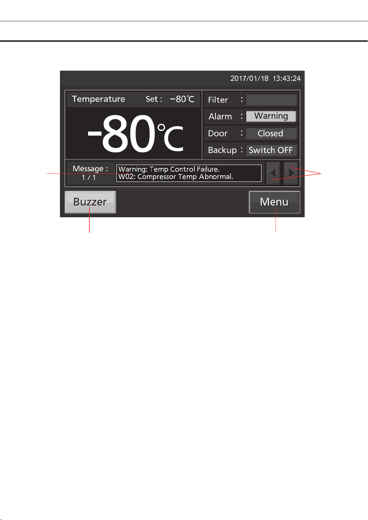
5. Alarm display: [pages 46 - 47]
Normal condition: “Normal” is displayed.
Alarm-activated, buzzer-delayed: “Alarm” is displayed alternately in normal characters and reverse video.
Alarm-activated, buzzer-sounding: “Warning” is displayed alternately in normal characters and reverse video.
6. Door (opening/closing) display:
Open: “Open” is displayed alternately in normal characters and reverse video.
Close: “Closed” is displayed.
7. Backup display: (It is displayed only when an optional backup cooling kit is installed) ON/OFF of the
backup power switch is displayed [page 56].
ON: “Switch ON” is displayed.
OFF: “Switch OFF” is displayed.
o
C.
1 2 3
4
5
6
7
12
FREEZER COMPONENTS
8
11 10
8. Message display field: The information of the operation monitor system, alarms or status are
displayed when fault occurs [pages 46 -47].
9. Message select key: When there are a number of alarms, status or information of the operation
monitor system, the message on the screen is changeable.
10. Menu key: Press this key to lead the Menu screen. It is possible to set various setting on the Menu
screen [page 20].
11. Buzzer key: Press this key to silence the buzzer. However, when the ring back is ON, the buzzer will
sound again when the ring back passed and the alarm state still continues [pages 29 - 30 and 48].
9
13

FREEZER COMPONENTS
Remote alarm terminal
The alarm of this unit can be informed at a remote location from this unit by connecting the external alarm
device to the remote alarm terminals. For the type and behavior of remote alarm output [pages 46 - 47].
The terminal of the remote alarm is installed at the right side
of the unit (See the figure on the point). The alarm is outputted
from this terminal. Contact capacity is DC 30 V, 2 A.
When Buzzer key is pressed, the behavior of the remote
alarm is showed in Table.1.
Note:
• In the door alarm, the remote alarm does not work [page 47]
• It is recommended to use standard signal and interface cables
with a maximum length of 30 meters.
Table 1 The behavior of the remote alarm when pressing Buzzer key
Remote Alarm setting
[pages 29 – 30]
ON:
Non-interlock with Buzzer key
OFF:
Interlock with Buzzer key
Remote alarm terminal
Abnormal condition
Connecting
terminal
COM.-N.C. Close Open Open (Maintain in abnormality)
COM.-N.O. Open Close Close (Maintain in abnormality)
COM.-N.C. Close Open Close (Return to normal)
COM.-N.O. Open Close Open (Return to normal)
Normal
condition
(Including in the cases of power outage and
of where the power plug is pulled out.)
When pressing Buzzer key
Air intake port (Manual)
The difference in pressure inside and outside of the chamber is adjusted automatically to open the outer door
smoothly.
However, if the door becomes heavy and difficult to open, follow the procedure below.
1. Turn the cap on the left side counterclockwise about two laps.
(Or remove the cap.)
2. Allow about twenty seconds before open the outer door.
3. Close (or replace) the cap when the door operation is
completed.
Remove the cap on the air intake port and check for the frost inside
the air intake port.
If excessive frost has built up in the air intake port, remove with a
"Stick for air intake port cleaning" [page 49].
CAUTION
For removing the frost in the air intake port, do not use a tool with sharp edge such as a knife or a screw
driver.
About 2 laps
Cap
14

INSTALLATION SITE
This unit must be installed in a location which meets all the conditions described below.
If the unit is installed in a location which does not meet the conditions, its specified performance may
not be achieved or malfunctions and accidents may occur.
■ A location not exposed to direct sunlight
Avoid any location which is exposed to direct sunlight. Installing the unit in a location exposed to direct
sunlight may reduce its cooling performance.
■ A well-ventilated (airy) location
In order to ensure ventilation, leave clearances of at least 10 cm around the unit (at the left, right, top and
back). Blocking the ventilation may reduce the unit’s cooling performance or cause malfunctions.
■ A location away from sources of heat
Avoid any location which is close to a major source of heat (such as a heater or boiler). Installing the
unit near a major source of heat may reduce the unit’s cooling performance.
■ A location with minimal changes in temperature
Avoid any location where the ambient temperature is subject to sudden changes. If the unit is installed
in a location where the ambient temperature is subject to sudden changes, it will not be possible to
achieve a stable cooling performance.
■ A flat surface where the floor is also capable of bearing the total combined weight (product +
optional accessories + stored items)
Install the unit on a flat surface which is even and which is capable of bearing the total combined weight
(product + optional accessories + stored items). If the unit is installed where the surface is uneven or
where the unit will be inclined at an angle, the unit will be unstable, and accidents or injuries may occur
and/or unnecessary vibration or noise may be generated.
■ A location with minimal humidity
Install the unit in a location where the relative humidity is less than 80 %R.H. Installing the unit in a very
humid location may cause earth faults and/or electric shock.
■ A location free of flammable or corrosive gases
Avoid any location exposed to flammable or corrosive gases. Flammable or corrosive gases can cause
explosions and/or a fire. Furthermore, corrosion of the electrical parts may cause the insulation to be
reduced and result in earth faults and/or electric shock.
■ A location where nothing can fall onto the unit
Avoid locations where objects may fall onto the unit. Objects falling and hitting the unit may cause it to
break down or fail.
15

INSTALLATION
When installing the unit, follow the steps below to secure the unit properly, and also be absolutely sure to
earth the unit.
In addition, install an earth leakage circuit breaker (on the unit’s power supply side), which is mandatory
under the applicable laws and regulations.
1. Preparations after unpacking
Remove all the tape used to secure the doors and interior parts, and leave the doors open for a short
while for ventilation.
If any surfaces of the outer cabinet are dirty, wipe the surface using a cloth moistened with a diluted
neutral dish-washing detergent.
Using an undiluted solution of detergent may cause the unit’s plastic areas to crack. Follow the
directions on the detergent for details of dilution.
After wiping the unit using the diluted detergent, be absolutely sure to wipe the surfaces with a cloth
dipped in clean water to remove traces of the detergent. After this, be absolutely sure to wipe the
surfaces with a dry cloth, allowing the surfaces of the outer cabinet to dry out completely, and then
proceed with the installation.
Note:
Remove the cable tie that bands the power supply cord. Prolonged contact with the tie may cause
corrosion of the cord coating.
2. Securing and levelling the unit using the levelling feet
Rotate the front levelling feet clockwise until the casters
are raised 5 mm to 10 mm above the floor surface. (Fig. 1)
In addition, rotate the levelling feet slightly clockwise or
anticlockwise, and adjust them so that the unit is
completely level.
When the casters are raised from the floor surface, the
unit will be secured. If they are left touching the floor, the
unit may accidently move when its door is opened or
closed.
3. Securing the unit by using the fixtures
Use the fixtures on the rear panel of the unit, and secure
the unit to a wall with a strong rope or chain. (Fig. 2)
Fig.1
Levelling feet
Fixture
Fig. 2
16

INSTALLATION
4. Preventing electric shock by earthing the unit
When installing the unit, be absolutely sure to earth (ground) it. Earthing is necessary to prevent electric
shock resulting from deterioration of electrical insulations
This unit comes with a 3-pin plug having one earth pin. Earthing work is not required in the case of a
3-pin power outlet equipped with an earth contact.
If the power outlet is not a 3-pin outlet equipped with an earth contact, ask a qualified contractor to do
the earthing work.
5. Setting up the shelves
Three shelves are packaged at the bottom of the chamber.
Set the shelves firmly in place on the shelf stoppers at the
standard locations. (Fig. 3)
6. Installing an earth leakage circuit breaker
Install an earth leakage circuit breaker (on the unit’s power
supply side), which is mandatory under the applicable laws
and regulations.
Contact our sales representative or agent to arrange the
installation of an earth leakage circuit breaker.
Shelf stopper
Fig. 3
17

START-UP PROCEDURE
Follow this procedure for the initial operation of the unit and for consequent operations (after temporary
stoppage for cleaning, maintenance or moving).
After a power failure, the unit will restart operation automatically with the same settings as before the
power failure. [page 19],
1. Check that the following switches are turned off: [power switch, battery switch, switch of the optional
back-up cooling kit (if installed)].
2. Connect the power supply cord to the dedicated power source with the appropriate rating with the
chamber empty.
3. Turn ON the power switch to start operation of the unit.
4. Turn on the battery switch.
Note: When the battery switch for power failure alarm is OFF, “S20: Battery Inactive, SW may be OFF.” is
displayed in the message display field. By turning ON the battery switch for power failure alarm, this
message disappears.
5. Set the desired chamber temperature [pages 23 - 24].
The factory setting of chamber temperature is -80
6. Using the temperature display, check that the chamber temperature has cooled to the set
temperature.
Check that the chamber temperature falls to the set temperature when the start-up after cleaning,
maintenance or moving.
7. Turn on the switch of the optional back-up cooling kit (if installed).
8. Do the alarm test. Make sure that the buzzer sounds by pressing Buzzer key for 5 seconds. Press
Buzzer key again to stop the buzzer and the alarm test finishes.
9. Press the test switch of the optional back-up cooling kit (if installed) to check it is working.
10. Gradually place the material inside the chamber.
Putting a large amount of material into the chamber at one time causes the temperature to rise.
11. Set the alarm temperature [pages 23 – 24] and the buzzer suspended period [pages 29 - 30], lock
the menu setting [pages 25 - 27], and set the compressor delay [pages 24 - 25], and door alarm delay
[pages 29 - 30] as required.
Note:
• When closing the outer door push the latch until the latch is locked in place. Insufficient pushing can
lead to temperature rise in the chamber.
• In case some optional inventory racks are in the chamber, be careful not to drop inventory rack when
pulling out it.
o
C.
18

DURING/AFTER POWER FAILURE
Operation during power failure
When the battery switch for power failure is ON, during a power failure the behavior of this unit is as
follows.
●The power failure alarm is activated [page 46].
Press Buzzer key to silence the buzzer of the power failure alarm. In case the ring back is turned ON,
buzzer sounds again when a power failure still continues after ring back set time passed [page 30].
●LCD touch panel is turn OFF [page 46].
By touching the LCD touch panel, it lights in the set brightness for 5 seconds.
●The High/Low Alarm is ready to activate during a power failure [pages 23 - 24 and 46].
An alarm message is displayed on the message display field. Alarm display, the buzzer and the remote
alarm (although it is of the power failure alarm) are already activated.
●The clock function does not stop.
●Operation log data and alarm log data during a power failure is saved.
Note: When the capacity of the battery for power failure alarm is flat during a power failure, subsequent
operation log data and alarm log data is not saved.
Operation after recovery from power failure
The set value is memorized by nonvolatile memory. Accordingly, the chamber resumes the operation with
setting before power failure.
Note:
• It may take up to 1 minute until the LCD touch panel lights after recovery from power failure.
• All products start at the same time as the recovery from the power failure, so that, the temporary voltage
drop may have a bad influence on the starting of this unit. To prevent this situation, set the appropriate
compressor delay time of this unit [pages 24 - 25].
Although the power failure alarm is canceled at the
recovery of the power failure, in order to remind
that power failure had happened, buzzer is
sounding and “Alarm” is displayed alternately in
normal characters and reverse video in the alarm
display [page 48]. By pressing Buzzer key, the
alarm display returns to “Normal” and the buzzer
stops.
Note: It is possible to confirm the past alarms in
the “Displaying alarm log” [pages 38 - 39].
19

BASIC OPERATION ON LCD TOUCH PANEL
A
♦Message select key:
(Operate) Changing some messages
♦Buzzer key: (Operate) Silencing the buzzer
(Alarm is not canceled except for some alarms; page 48)
●Operation from Menu key
■Menu screen
♦Set →
♦Log →
♦Chart →
♦Actual Temp. (Display) Chamber temp. log graph (can be exported) 32~34
♦Door Opening (Display) Door opening log graph (can be exported) 32~34
♦Actual Temp. (Export) Chamber temperature log 35~37
♦Door Opening (Export) Door opening log 35~37
♦Setting (Setting) Log interval, Unique ID 31~32
♦Alarm (Display)
♦Alarm Export (Export) Alarm log 40~41
♦Key Lock →
♦Tools →
♦Operation Setting (Setting) Comp. delay time 24~25
♦Alarm Setting (Setting) Alarm delay, ring back, remote alarm etc. 29~30
♦DAQ Setting Do not press (It is not possible to set.)
♦Date & Time (Setting) Date, time 43
♦Brightness/Sleep (Setting) Brightness, sleep ON/OFF etc. 44~45
Page
■Temp. Setting screen
■Log screen
■Chart screen
Data
♦
Export
■Key Lock screen
■Tools screen
→
■Export screen
(Setting) Temp., High Alarm, Low Alarm 23~24
larm log (can be exported) 38~39
(Setting) Key lock ON/OFF, password 25~28
20

BASIC PARAMETERS
How to input numerical value and alphanumeric character
On each screen in the LCD touch panel, it may be necessary to input numerical value or alphanumeric
characters.
●When inputting numerical value
1. By pressing numeric input box, numeric input
window is displayed.
2. Press Numeric key or Up/Down key to input
numerical value, and press OK key.
●Key description
• Numeric key (0~9): Input numerical value.
• Up/Down key (▲/▼): Increases or decreases the numerical value displayed in the numeric input box.
• Clear key: Deletes the numerical value displayed on the numeric input box.
• Cancel key: Stops inputting on the numeric input box and closes the input window.
Note: Up/Down key may not be displayed.
Numeric input box
Numeric input window
21

BASIC PARAMETERS
●When inputting alphanumeric characters
1. By pressing alphanumeric input box, alphanumeric
input window is displayed.
2. Press alphabetic key and numeric key to input
alphanumeric characters, and press OK key.
●Key description
• Alphabetic key (A~Z, Space): Input alphabetic characters or spaces.
• Numeric key (0~9): Input numerical values.
• UC/LC key (A a): Change UC/LC of alphabetic key.
• Left/Right key ( / ): Move the cursor to left/right.
• Delete key: Delete an alphanumeric character on the left side of the cursor.
• Cancel key: Stops inputting on the alphanumeric input box and closes the alphanumeric input window.
Note: While the alphanumeric input window is open, it is not possible to operate Top key and Back key.
[Auto return function]
When there is no key operation for about 90 seconds on the screen excluding the top screen: Exit the
setting mode and return to the top screen.
<
When the sleep function is on >
When there is no key operation for about 90 seconds without alarm / error after sleep state: Exit the
setting mode and return to the top screen.
Alphanumeric input box
Alphanumeric input window
22

BASIC PARAMETERS
Setting Temperature, High Alarm and Low Alarm
Set the Temperature, High Alarm and Low Alarm for normal operation according to the following
procedure. The unit automatically starts operation using these settings after power-on.
1. Press Menu key to lead the Menu screen.
2. Press Set key to lead the Temp. Setting
screen.
3. Input each parameter. Press Apply key to
save the input value. The display returns to the
Menu screen.
●Each parameter setting
• Temperature: Set value of chamber temperature.
Settable range: -90
• High Alarm: When the chamber temperature exceeds the High Alarm set temperature (= the set
temperature + the set value of High Alarm)*, the High Alarm is activated.
Settable range: +5
• Low Alarm: When the chamber temperature falls below the Low Alarm set temperature (= the set
temperature - the set value of Low Alarm)*, the Low Alarm is activated.
Settable range: -40
o
C~-50 oC, Control range: -86 oC~-50 oC, factory setting: -80 oC.
o
C~+40 oC, factory setting: +10 oC.
o
C~-5 oC, factory setting: -10 oC.
23

BASIC PARAMETERS
* The current chamber temperature is the value rounded off below a decimal point, so the High/Low
Alarm may be activated when the value of the current chamber temperature is equal to the High/Low
Alarm set temperature.
4. On the Menu screen, press Back key to return to the Top screen.
Setting operation control mode
1. Press Menu key to lead the Menu screen.
2. Press Tools key to lead the Tools screen.
3. Press Operation Setting key to lead the
Operation Setting screen.
24

BASIC PARAMETERS
4. Input each parameter. Press Apply key to
save the input value and setup. The display
returns to the Tools screen.
●Each setting
• Compressor Delay:
The time from turning ON this unit until starting its compressor. This unit is required a large electric power
at the moment its compressor starts. When some units are in a same room, set so as to be shifted to
each other the compressor delay times, to prevent the simultaneous start of all compressors after power
failure. Settable range: 3 minutes~15 minutes, factory setting: 3 minutes.
5. Press Top key to return to the Top screen.
Setting key lock
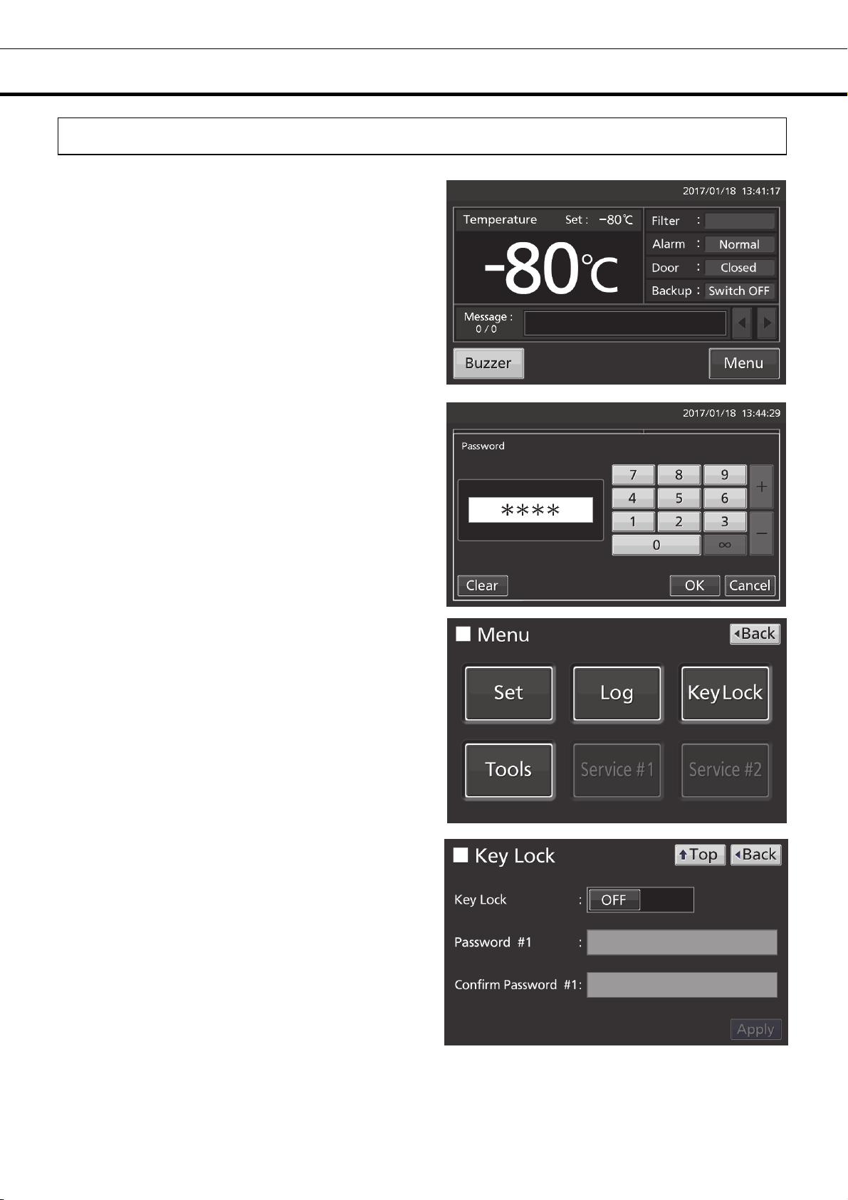
1. Press Menu key to lead the Menu screen.
2. Press Key Lock key to lead the Key Lock
screen.
25

BASIC PARAMETERS
3. On the Key Lock screen, it is possible to set
each setting of key lock.
• Key Lock: By holding Key Lock slide key and
sliding it to the right, Key Lock turns to ON.
• Password #1: The number (Max. 6 digits)
inputted here are registered the release password
of Key Lock.
• Confirm Password #1:
To prevent erroneous input, input the same
password as Password #1 input box. When
inputting different password, Notice dialog box is
displayed. Press OK key and input the correct
password.
• By pressing Apply key, Key Lock turns to ON,
password #1 is saved, and Confirm dialog box is
displayed.
Yes: On the Key Lock screen, it is possible to set
the release password #2.
No: The display returns to the Menu screen.
Select [No]when it is no need to set the password
#2.
Note: Two release passwords of Key Lock are
settable. To release it, you can unlock by entering
one of the passwords.
4. Set the password #2.
• Password #2: The number (Max. 6 digits)
inputted here are registered the release password
of Key Lock.
Confirm Password #2:
To prevent erroneous input, input the same
password as Password #2 input box. When
inputting different password, Notice dialog box is
displayed. Press OK key and input the correct
password.
• By pressing Apply key, the password #2 is saved
and Information dialog box is displayed.
26

BASIC PARAMETERS
5. On the Information screen, press OK key to
return to the Menu screen.
6. On the Menu screen, press Back key to return to the Top screen.
Note: Manage the release password of Key Lock properly.
●Operation for Keylock-ON
• When pressing Menu key, Password input box is
displayed, and input of the release password of
Key Lock is required. If two passwords are
registered, you can unlock by entering one of the
passwords
• When the inputted password is incorrect, Notice
dialog box is displayed. Press OK key, and then
input the correct password.
27
BASIC PARAMETERS
Removing key lock
1. By pressing Menu key, the Password input
window is displayed.
2. On Password input box, input the set release
password (#1 or #2) of Key Lock, and press OK
key to lead the Menu screen.
3. Press Key Lock key to lead the Key Lock
screen.
4. On the Key Lock screen, by holding Key Lock
slide key and sliding to the left, change to OFF.
Press Apply key to turn the key lock OFF. The
display returns to the Menu screen.
Note: The release password of key Lock is
deleted.
5. On the Menu screen, press Back key to return
to the Top screen.
28

ALARM PARAMETERS
1. Press Menu key to lead the Menu screen.
2. Press Tools key to lead the Tools screen.
3. Press Alarm Setting key to lead the Alarm
Setting screen.
29
ALARM PARAMETERS
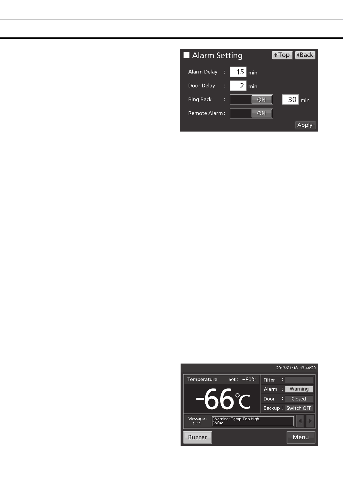
4. On the Alarm Setting screen, it is possible to
set each setting. Press Apply key to save the
input value and setup. The display returns to the
Tools screen.
●Each setting
• Alarm Delay:
The function is that when the unit is in the alarm state of High Alarm or Low Alarm, the alarm buzzer will
sound after the alarm delay set time passed.
Settable range: 0 minute~15 minutes, factory setting: 15 minutes.
Note: When the unit is recovered from the alarm state within the alarm delay time, the buzzer does not
sound after the elapse of the alarm delay.
• Door Delay:
The function is that when the unit is in the alarm state of door, the alarm buzzer will sound after the alarm
delay set time passed. Settable range: 0 minute~15 minutes, factory setting: 2 minutes.
Note: When the unit is recovered from the alarm state within the door alarm delay time, the buzzer does
not sound after the elapse of the door alarm delay.
• Ring Back:
The function is that the alarm buzzer sounds again when the alarm state still continues after the ring back
set time passed even though the alarm buzzer was stopped by pressing Buzzer key. By holding and
sliding Ring Back slide key to the right, the Ring Back is turned to ON.
Settable range: 1 minute~99 minutes, factory setting: 30 minutes.
Note: At Door alarm, the alarm is not re-activated because the alarm itself is deactivated by pressing
Buzzer key [page 48].
• Remote Alarm:
The function is that the remote alarm is continued even though the buzzer is stopped by pressing Buzzer
key. By holding and sliding Remote Alarm slide key to the right, the Remote Alarm is turned to ON (not in
conjunction with Buzzer key). Factory setting: ON.
5. Press Top key to return to the Top screen.
●
At the alarm state
• While the unit’s alarm is being activated and the
buzzer is being sounding, the buzzer is silenced by
pressing Buzzer key. For the behavior at the time
of pressing Buzzer key and the re-activation of
alarm, under each setting condition, refer to Table
2-3 on page 48.
Resolve the cause of the alarm in reference to
pages 46 - 48 because the alarm itself is not
deactivated by pressing Buzzer key except for
some alarms.
30

OPERATION/ALARM LOG
Setting log interval
The unit is equipped with a function of saving operation log data (chamber temperature and open/close
state of door).
Note: When the battery switch for power failure alarm is ON, operation log is saved during a power
failure.
Use the following procedure to set the log interval (interval of acquiring the operation log).
1. Press Menu key to lead the Menu screen.
2. Press Log key to lead the Log screen.
3. Press Setting key to lead the Setting screen.
31

OPERATION/ALARM LOG
4. On the Setting screen, input Log Interval. Press
Apply key to save the input value. The display
returns to the Log screen.
Settable range: 2 minutes~30 minutes.
Factory setting: 6 minutes.
Note: Only an even number can be inputted.
When inputting an odd number and when pressing
OK key in the numeric input window, it changes to
an even number which is 1 smaller than that.
Note: It is possible to register 8-digit alphanumeric
characters as the Unique ID [page 37].
Note: Relation between log interval and the estimated amount of data that can be saved
Log interval=2 minutes: Approx. 46 days
Log interval=6 minutes: Approx. 135 days
Log interval=30 minutes: Approx. 664 days
When saving data more than the above, and the data is overwritten and the old data is delated.
5. Press Top key to return to the Top screen.
Displaying operation log
Operation log saved in the freezer can be displayed graphically on the LCD touch panel.
1. Press Menu key to lead the Menu screen.
2. Press Log key to lead the Log screen.
32

OPERATION/ALARM LOG
3. Press Chart key to lead the Chart screen.
4. On the Chart screen, input the date (year /
month / day) of the operation log you want to
display graphically.
5. On the Chart screen, by pressing Show key
after pressing the item you want to display
graphically, the graph of each operation log is
displayed.
• Actual Temp.:
Chamber temperature log graph
(Go to procedure 6)
• Door Opening:
Open/close state of door log graph
(Go to procedure 7)
6. Actual Temp. log graph is displayed.
• Press Back key to return to the Chart screen.
• Press Top key to return to the Top screen.
To previous day To next day
To Door Opening log
33

OPERATION/ALARM LOG
To Actual Temp. log
7. Door Opening log graph is displayed.
• Press Back key to return to the Chart screen.
• Press Top key to return to the Top screen.
●On the Chart screen of procedure 6 or 7 log data can be exported in CSV format to the USB memory
inserted into the USB port.
To previous day
To next day
8. Insert the USB memory into the USB port.
Note: It is not possible to use a USB memory with security functions that requires entering password.
9. Press Export key.
10. When the export is complete, Information
dialog box is displayed. Press OK key. Refer to
pages 36 and 37 for the details about abnormal
export or exported file name.
11. Press Top key to return to the Top screen.
34

OPERATION/ALARM LOG
Exporting operation log
Operation log data saved in the freezer can be exported in CSV format to the USB memory inserted into
the USB port.
1. Insert the USB memory into the USB port.
Note: It is not possible to use a USB memory with security functions that requires entering password.
2. Press Menu key to lead the Menu screen.
3. Press Log key to lead the Log screen.
4. Press Data Export key to lead the Export
screen.
35

OPERATION/ALARM LOG
5. On the Export screen, select the time period
you want to export.
• To export the saved operation log data over the
entire period, press All radio button.
• To export the operation log data of a specified
date, press 1 Day radio button and input the date
(year / month / day) of the operation log data you
want to export.
Note: The error of about 1 minute may be
observed during a month. Refer to page 43 for the
procedure of setting time.
6. On the Export screen, select the type of
operation log data you want to export.
• To export all types of operation log data, press All
Ch key.
• To export only operation log data you want to
export, select operation log data you want to export,
and then press Selected Ch key.
• Actual Temp.: Chamber temperature log data
• Door Opening: Open/close state of outer door log
data
Note: When no USB memory is inserted into
the USB port, Notice dialog box is displayed.
Press OK key, and then insert a USB memory
into the USB port.
36

OPERATION/ALARM LOG
Note: When the specified operation log data
does not exist, Notice dialog box is displayed.
Press OK key, and then re-specified according
to procedure 5 and 6.
7. When the export is complete, Information
dialog box is displayed. Press OK key.
Note: Even after the export of operation log
data is complete, operation log data saved in
the unit are not deleted.
8. Remove the USB memory from the USB port.
Note:
• The log folder is created in the USB memory, and the exported file is saved in it in CSV format. The
exported file name is in date (8 digits) - type of data format.
(e.g.) When exporting all types of data using All (from Jan. 1st, 2017 to Oct. 1st, 2017):
20170101-20171001_AllCh.csv
20170101-20171001_Door.csv
(e.g.) When exporting Actual Temp. using 1 Day (Jan. 1st, 2017):
20170101_Temp.csv
If the file name is duplicated, A sequential number such as "-1" is added to the end of the file name to
be output later.
• On the beginning of the exported file, product name (“MDF-DU502VH” or “MDF-DU702VH”) is written.
However when the Unique ID is registered [page 32], product name and Unique ID (8-digit) are written.
(e.g.) When “RoomA001” is set as the Unique ID of MDF-DU702VH:
MDF-DU702VH, RoomA001
9. Press Top key to return to the Top screen.
37

OPERATION/ALARM LOG
Displaying alarm log
The unit is equipped with a function of saving alarm log data (Max. 256 logs).
Note:
• When saving alarm logs more than 257, the oldest alarm log is deleted, and then overwritten.
• When the battery switch for power failure alarm is ON, operation log is saved during a power failure.
Alarm log saved in the freezer can be displayed graphically on the LCD touch panel.
1. Press Menu key to lead the Menu screen.
2. Press Log key to lead the Log screen.
3. Press Alarm key to lead the Alarm screen.
38

OPERATION/ALARM LOG
4. On the Alarm screen, the newest 7 days’ alarm
logs (containing that day) are displayed.
Note: When the number of applicable alarm log is
6 or more, by pressing the top (▲) or the bottom
(▼) log, the log table currently displayed scrolls
and hidden alarm logs can be seen.
• Press Back key to return to the Log screen.
• Press Top key to return to the Top screen.
5. On the Alarm screen, by inputting days into the
Last XX Days input box, alarm logs for specified
days (containing that day) are displayed.
Settable range: 1 day~45 days.
Note: The error of about 1 minute may be
observed during 1 month. Refer to page 43 for the
procedure of setting time.
• Press Back key to return to the Log screen.
• Press Top key to return to the Top screen.
●On the Alarm screen of procedure 4 or 5, alarm log data can be exported in CSV format to the USB
memory inserted into the USB port.
6. Insert the USB memory into the USB port.
Note: It is not possible to use a USB memory with security functions that requires entering password.
7. Press Export key.
8. When the export is complete, Information
dialog box is displayed. Press OK key. Refer to
pages 41 and 42 for the details about abnormal
export or exported file name.
9. Press Top key to return to the Top screen.
39

OPERATION/ALARM LOG
Exporting alarm log
It is possible to export saved alarm log data to a USB memory inserted in the USB port by CSV format.
1. Insert a USB memory in the USB port.
Note: It is not possible to use a USB memory with security functions that requires entering password.
2. Press Menu key to lead the Menu screen.
3. Press Log key to lead the Log screen.
4. Press Alarm Export key to lead Alarm Export
screen.
40
OPERATION/ALARM LOG
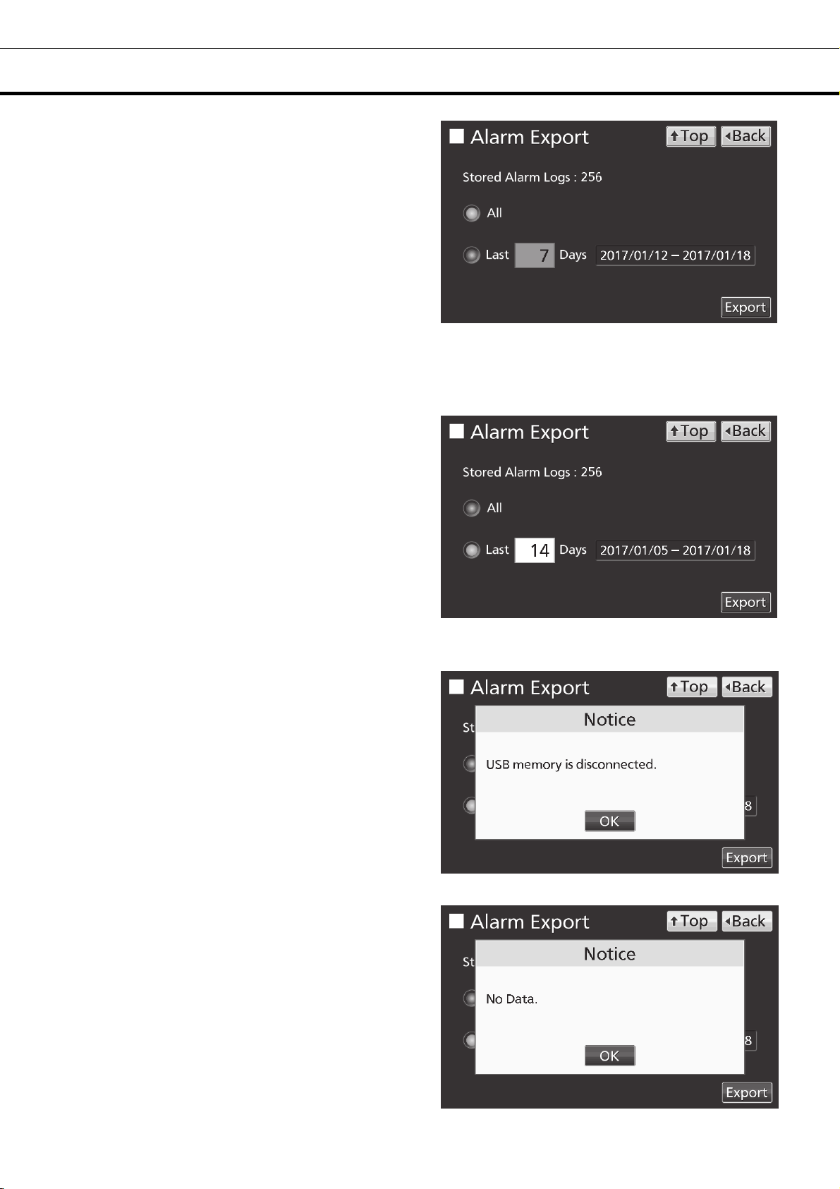
5. On the Alarm Export screen, select the period
to export.
• To export the saved alarm log data over the
entire period, press All radio button.
• To export the alarm log data for the specified
days (The newest period containing that day),
press Last XX Days radio button and input days.
Settable range: 1 day~45 days.
Note: The error of about 1 minute may be
observed during 1 month. Refer to page 43 for
the procedure of setting time.
6. Press Export key.
Note:
• When USB memory is not inserted in the USB
port, Notice dialog box is displayed. Press OK
key and insert an USB memory into the USB
port.
• When alarm log data does not exist in the
specified days, Notice dialog box is displayed.
Press OK key and specify days again as shown
in the procedure 5.
41

OPERATION/ALARM LOG
7. Even after completion the export of alarm log
data, Information dialog box is displayed. Press
OK key.
Note: After completing the export of alarm log
data, alarm log data saved at unit is not deleted.
8. Remove a USB memory from the USB port.
Note: A log folder is created in a USB memory, and an exported data file is saved in the log folder by
CSV format.
Exported file name; The first date during exported period (8 digits) + the last date (8 digits) + AlarmLog
Example) When exporting alarm log data for 7 days on January 7, 2017;
20170101-20170107_AlarmLog.csv
If the file name is duplicated, A sequential number such as "-1" is added to the end of the file name to
be output later.
9. Press Top key to return to the Top screen.
42

OTHER PARAMETERS
Setting date and time
1. Press Menu key to lead the Menu screen.
2. Press Tools key to lead the Tools screen.
3. Press Date & Time key to lead the Date &
Time screen.
4. On the Date & Time screen, input the present
date and time. Press Apply key to save the input
value. The display returns to the Tools screen.
Note:
• 24-hour clock.
• It is recommended to set the time periodically
since the error of about 1 minute may be observed
during a month.
5. Press Top key to return to the Top screen.
43
OTHER PARAMETERS
Setting brightness and sleep
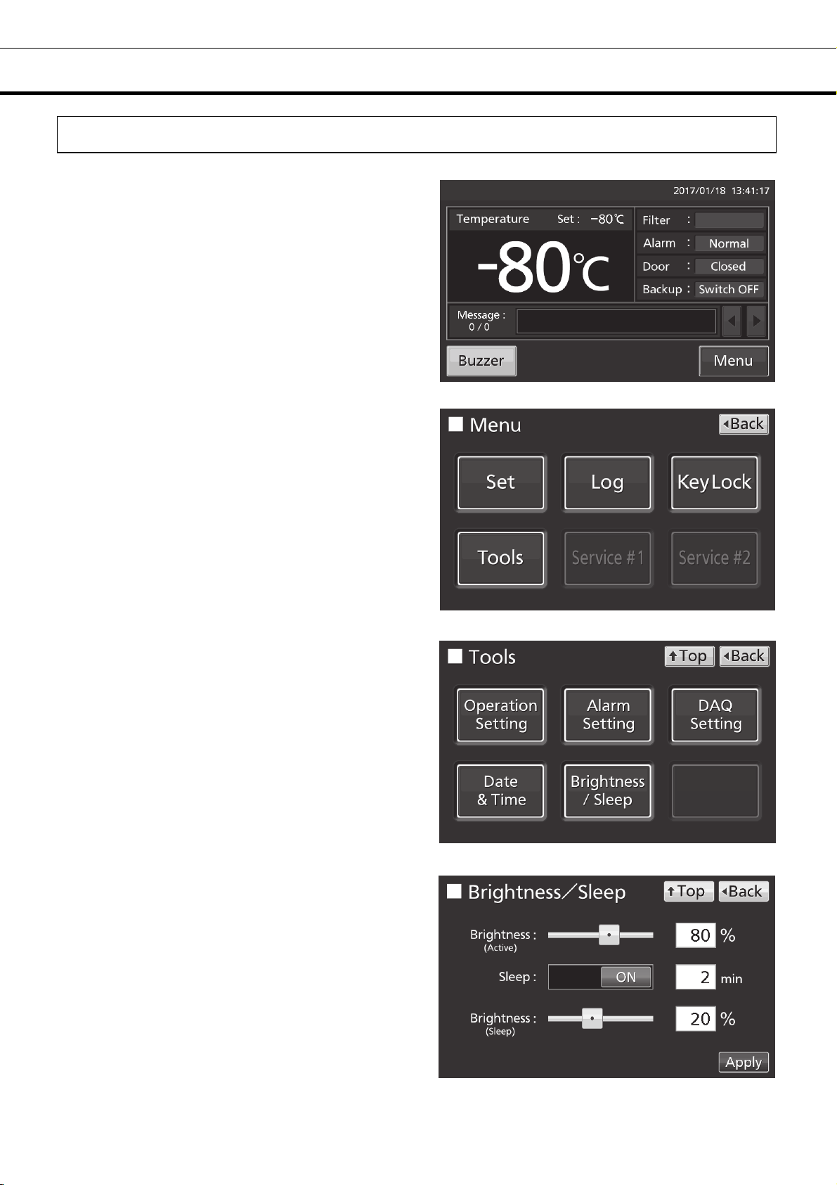
1. Press Menu key to lead the Menu screen.
2. Press Tools key to lead the Tools screen.
3. Press Brightness/Sleep key to lead the
Brightness/Sleep screen.
4. On the Brightness/Sleep screen, each setting of
brightness and sleep is available. Press Apply key
to save the input value and setup. The display
returns to the Tools screen.
44

OTHER PARAMETERS
●Each setting
• Brightness(Active):
Brightness of LCD touch panel of the usual state. Adjust Brightness(Active) slide bar or input set value
into the Brightness(Active) input box. Settable range: 50~100, factory setting: 80.
• Sleep:
The function is that the brightness of LCD touch panel is lowered to save electricity, when there is no key
operation during set time.
By holding the Sleep slide key and sliding it right, the Sleep function is turned to ON. Input the set value
of time to change the Sleep state. Settable range: 1 minute~5 minutes, factory setting: 2 minutes.
Note: It is not possible to operate any key in the Sleep state. By touching the LCD touch panel, the Sleep
state is released and the LCD touch panel returns to the usual state. Under this condition, key operations
are available.
• Brightness(Sleep):
Brightness of LCD touch panel of the Sleep state. Adjust Brightness(Sleep) slide bar or input set value
into the Brightness(Sleep) input box. Settable range: 0~50, factory setting: 20.
5. Press Top key to return to the Top screen.
45

ALARMS AND SELF-DIAGNOSIS
Warning: The cooling performance is significantly reduced. The chamber temperature may get higher
considerably. Take some precautions for the storage items immediately (transferring the storage items
to another freezer or placing of dry ice wrapped in newspaper in the chamber) except when the cause is
clear and the chamber temperature can be recovered soon.
Contact our sales representative or agent after turning off the power switch.
LCD touch panel
Message display field
Warning: Temp Control Failure.
W01: Power Failure.
Warning: Temp Control Failure. *1
W02: Compressor Temp Abnormal.
Warning: Temp Too High.
W04
Warning: Temp Too Low.
W05
Warning: Temp Control Failure.
W06: Compressor 'H' Control Failure.
Warning: Temp Control Failure.
W07: Compressor 'L' Control Failure.
Warning: Temp Control Failure. *3
W08: Temperature Controller Failure.
Warning: Temp Control Failure. *2
W09: Temperature Sensor Error.
Warning: Temp Control Failure. *2
W10: Temperature Sensor Error.
Situation Buzzer
The battery switch for power failure alarm is
ON, and under any of the following
conditions.
•During a power failure
•Power switch is OFF
•Power supply cord is disconnected.
Compressor Temp Abnormality.
If the chamber temperature exceeds the
set temp. + the set value of High Alarm.
If the chamber temperature falls below the
set temp. - the set value of Low Alarm.
Compressor control failure due to
communication failure of H side inverter
Compressor control failure due to
communication failure of L side inverter
When communication between LCD touch
panel and control substrate is died out or
unstable.
If the thermal sensor is disconnected.
If the thermal sensor is short-circuited.
Intermittent
tone
― ― Communication error
Intermittent
tone
Remote
alarm
Alarm
mode
Alarm
mode
Alarm & safety
Power failure
alarm
Compressor Temp
Abnormality *1
High Alarm
Low Alarm
Communication error
Communication error
Temperature Sensor
disconnected *2
Temperature Sensor
short-circuited *2
*1:The compressor stops in the case of W02.
*2:The compressor runs continuously in the case of W09 or W10.
The compressor stop has a priority over the continuous running if the above two errors come up at one time.
*3:The chamber temperature is not displayed in the case of W08
Alarm: Cooling performance may decline and the temperature of the chamber may rise. Wait for the
recovery of chamber temperature if the temperature change is temporary resulting from user operation.
For other cases, failure or chamber temperature rise may cause if this status continues.
Take some precautions for the storage items (transferring the storage items to another freezer or placing
of dry ice wrapped in newspaper in the chamber).
Contact our sales representative or agent.
LCD touch panel
Message display field
Alarm: Temp Too High.
A04
Alarm: Temp Too Low.
A05
Situation Buzzer
If the chamber temperature exceeds the
set temp. + the set value of High Alarm.
If the chamber temperature falls below the
set temp. - the set value of Low Alarm.
― ―
Remote
alarm
Alarm & safety
High Alarm
Low Alarm
46

ALARMS AND SELF-DIAGNOSIS
Status: There is a possibility of failure other than the cooling performance. The chamber temperature is
under control. The alarm may not be triggered in the case of any failure if this status continues
Contact our sales representative or agent.
LCD touch panel
Situation Buzzer
Message display field
Remote
alarm
Alarm & safety
Status: Temp Control Risk. *4
S01: Cooling Circuits Overload.
Status: Temp Under Control. *5
S02: Ambient Temp Abnormal.
Status: Temp Under Control.
S03: Air Intake Port Heater Failure.
Status: Temp Under Control.
S10: Cascade Sensor Error.
Status: Temp Under Control.
S11: Cascade Sensor Error.
Status: Temp Under Control.
S12: Filter Sensor Error.
Status: Temp Under Control.
S13: Filter Sensor Error.
Status: Temp Under Control.
S14: Ambient Temp Sensor Error.
Status: Temp Under Control.
S15: Ambient Temp Sensor Error.
Status: Temp Under Control.
S16: Main Battery Charging Failure.
Status: Temp Under Control.
S17: Backup Battery Charging Failure.
Status: Temp Under Control.
S18: Exchange a Main Battery.
Status: Temp Under Control.
S19: Exchange a Backup Battery.
Status: Temp Under Control.
S20: Battery Inactive, SW may be OFF.
When the chamber temp. does not reach
the set temp. for approx. 5 days or more.
When the ambient temp. is over 35 oC or
o
lower than 0
Heater failure.
When the cascade sensor disconnected.
When the cascade sensor short-circuited.
When the filter sensor disconnected.
When the filter sensor short-circuited.
When the ambient temp. sensor
disconnected.
When the ambient temp. sensor
short-circuited.
When the battery voltage does not
increase after certain period.
When the cumulative operating time
exceeds about 3 years.
When about 3 years passed after installing
backup cooling kit.
When the battery switch for power failure
alarm is OFF.
C.
―
Intermittent
tone
―
―
Overload operation
*4
Abnormal ambient
temperature *5
Air Intake Port
Heater Failure
Cascade Sensor
disconnected
Cascade Sensor
short-circuited
Filter Sensor
disconnected
Filter Sensor
short-circuited
Ambient Temp Sensor
disconnected
Ambient Temp Sensor
short-circuited
Main Battery
Charging Failure
Backup Battery
Charging Failure
Battery for power
failure alarm
replacement
Battery for backup
cooling kit
replacement
Battery switch check
Door Open. When door is open.
*4: In the case of S01, check the following:
(1) There are too many items stored inside the chamber at a time.
(2) The door is frequently opened. The door seal is damaged.
(3) The set chamber temperature is higher than -80
*5: Check the air conditioning at the installation site in the case of S02.
o
The ambient temperature should be 5
C~30 oC.
o
C.
Intermittent tone
(After door delay
time has
elapsed.)
Door alarm
47

ALARMS AND SELF-DIAGNOSIS
●Table 2
Table 2 In the cases of other than the door alarm.
Remote Alarm setting
ON: Non-interlock
with Buzzer key
OFF: Interlock
Note: Resolve the cause of the alarm in reference to pages 46 - 47 because the alarm itself is not
deactivated by pressing Buzzer key.
Table 3 In the cases of the door alarm.
Remote Alarm setting
ON: Non-interlock
with Buzzer key
OFF: Interlock
●Table 4 shows the situation after being canceled the High/Low Alarm and recovery from a power failure
with no operation.
Table 4 The situation after being canceled the High/Low Alarm and recovery from a power failure with
no operation
Canceled alarm
~3 show the behavior of the alarm (buzzer) and Ring Back function when pressing Buzzer key.
Buzzer from unit Remote Alarm
OFF
Buzzer from unit
OFF
LCD touch panel
with Buzzer key
with Buzzer key
Message display field Alarm display
Ring Back
setting
ON
OFF OFF
ON ON
OFF OFF OFF
Ring Back
setting
ON
OFF
ON
OFF
When pressing
Buzzer key
(Alarm is not
canceled)
When pressing
Buzzer key
(Alarm is
canceled)
When the Ring Back
set time passes
ON
When the Ring Back
set time passes
OFF
(Alarm is already
canceled)
When pressing
Buzzer key
ON
OFF (Alarm is
not canceled)
Remote Alarm setting
Buzzer
When the Ring Back
set time passes
ON
(Under continuation)
ON
OFF
Remote
alarm
Safety
operation
High Alarm
Low Alarm
Power failure
alarm
Note: By pressing Buzzer key, the alarm display returns to “Normal” and buzzer stops.
―
―
“Alarm” is displayed alternately in
normal characters and reverse video
“Alarm” is displayed alternately in
normal characters and reverse video
Intermittent
Intermittent
tone
tone
― ―
― ―
48

ROUTINE MAINTENANCE
Cleaning the exterior, interior, and accessories
Use a dry cloth to wipe down the outside and inside of the unit and all accessories. If the outside panels
are dirty, clean them with a diluted neutral dish-washing detergent.
Wipe off condensation from the exterior of the cabinet with a dry, soft cloth.
Using an undiluted solution of detergent may cause the unit’s plastic areas to crack. Follow the
directions on the detergent for details of dilution.
After the wiping the cabinet or accessories with a diluted detergent, be absolutely sure to wipe the
surfaces with a cloth dipped in clean water to remove traces of the detergent. After this, be absolutely
sure to wipe the surfaces with a dry cloth.
<Important>
■ Do not use a brush, an acid, a thinner, laundry soap, a powder detergent, or boiling water for cleaning.
These may cause damage to painted surfaces or cause perishing of plastic and rubber components.
Moreover, do not wipe plastic and rubber components with a volatile material.
■ In order to maintain the unit’s intended level of performance, always replace accessories that have
been removed for cleaning.
Cleaning of air intake port (Manual)
Using the cap for air vent is likely to build a frost in/around the air intake port. Clean it in the case shown
below.
Condition Check / Remedy
When frost and ice can be
seen in the air intake port.
The outer door does not
open even if the cap of the
air intake port is opened.
Frost and ice can be seen in
the chamber.
WARNING
For removing the frost in the air intake port, do not use a tool with sharp edge such as a knife or a screw
driver.
The pipe of the air intake port is thrust with a stick for air intake port
cleaning of the accessories, and frost is taken.
The pipe of the air intake port is thrust with a stick for air intake port
cleaning of the accessories, and frost is taken.
Frost and ice inside the chamber are taken with scraper of the
accessories.
49

ROUTINE MAINTENANCE
Cleaning of condenser filter
This unit is provided with the filter alarm indicator on the LCD touch panel. Clean the condenser filter
when this indicator is lit. Clean the condenser filter once a month even if the filter alarm indicator is not
on. A dusty condenser filter may cause shorter compressor life as well as the poor cooling.
Clean the condenser filter by the procedure below.
1. Open the grille by pulling it to you as shown in the
figure.
2. Take out the condenser filter.
3. Wash the condenser filter with water.
4. Replace the condenser filter and the grille. (Set the
handle of the condenser filter at the front.)
5.
Check that the filter alarm indicator is off in the event
the filter alarm indicator was ON.
Condenser
filter
Grille
WARNING
Do not touch the condenser directly when the filter is removed for cleaning. This may cause injury by
hot surface.
50

ROUTINE MAINTENANCE
Defrosting of chamber
Frost may accumulate near the top of the chamber, near the door in the chamber, or near the air intake
port (Auto). Excessive accumulation of frost is likely to create gaps between the door and the door
gasket, which can reduce the cooling performance. Remove the frost from the chamber and the inner
door with the scraper enclosed with the unit. Use the following procedure for defrosting when excessive
frost builds up in the chamber.
Note:
Do not use tool with a sharp edge (such as a knife or screw-driver) to remove the frost.
1. Turn off the switch for the back-up cooling kit (if installed).
2. Take out all contents from the freezer and transfer them
to another freezer or a container which is refrigerated by
liquid carbon dioxide or dry ice.
3. Turn off the power switch and battery switch of the
freezer.
4. Open the outer door and inner door. Remove the
inner door by lifting up as shown in the figure.
5. Leave the freezer in this state until the frost in the
chamber melts.
6. Wipe up the water that accumulates at the bottom of the
chamber with a dry cloth.
7. After cleaning the chamber, replace the inner door and
start up the unit according to the procedure on page 18.
8. Check that the chamber temperature reaches the set temperature and then replace the contents.
9. Turn on the switch for the back-up cooling kit (if installed).
WARNING
Always wear gloves when mounting and/or removing the inner door to prevent injury.
CALIBRATION
During continuous operation, the following service tasks must be performed:
• Perform a temperature calibration at least once a year.
For temperature calibration, contact our sales representative or agent.
51

REPLACEMENT OF WORN-OUT PARTS
Replacing the battery for power failure alarm
Replace the battery for power failure alarm about every 3 years. Contact our sales representative or agent
for the replacement of battery when “S18: Exchange a Main Battery.” is displayed in the message display
field.
The replacement of the battery for power failure alarm is a paid service.
The alarm function (message display, sound of buzzer and remote alarm) will not operate when the battery for
power failure alarm is flat.
“W01: Power Failure.” is displayed and the buzzer sounds by the battery for power failure alarm.
WARNING
«Important» The used battery is a recyclable resource. Do not dispose of the battery.
Always follow the procedure for recycling.
The replacement of the battery for power failure alarm
should be executed by a qualified engineer or service
personnel only.
alarm involves the risk of electric shock.
The replacement of the battery for power failure
Replacing the battery for backup cooling kit
Replace the battery for backup cooling kit about every 3 years. Contact our sales representative or agent for
the replacement of battery when “S19: Exchange a Backup Battery.” is displayed in the message display
field.
The replacement of the battery for backup cooling kit is a paid service.
The backup cooling kit will not operate when the battery for backup cooling kit is flat.
When the chamber temperature rises, the backup cooling kit is activated by the battery for backup cooling kit
even during a power failure. The regular replacement of the battery for backup cooling kit is important to
prevent the rise of chamber temperature in the case of unexpected situation.
52
WARNING
«Important» The used battery is a recyclable resource. Do not dispose of the battery.
Always follow the procedure for recycling.
The replacement of the battery for backup cooling kit should
be executed by a qualified engineer or service personnel
only.
involves the risk of electric shock.
The replacement of the battery for backup cooling kit

TROUBLESHOOTING
If the unit malfunctions, check out the following before calling for service.
<Attention>
If the malfunction is not resolved after checking the following items or if the malfunction is not shown in
the table below, contact our sales representative or agent.
Malfunction Check/Remedy
Nothing operates even
when the power supply
plug is plugged in
The compressor does not
operate at all when turning
ON the power switch.
(LCD touch panel is turned
ON)
The alarm is activated
during operation
Excessive noise □ The floor is not stable.
The chamber does not
get cold enough
The outside of the unit is
wet with dew.
Noisy in motor sound or
flowing liquid.
Note:
• Keep an electric product which emits an electromagnetic wave away from this unit. A noise from an
electromagnetic wave may cause malfunction to this unit.
□ The unit is not connected to the power supply properly.
□ The capacity and voltage of the power supply is not sufficient.
□ There is a power failure.
□ The circuit breaker on the supply circuit is activated.
□ The fuse on the supply circuit is blown.
□ The capacity of power supply is not sufficient. When the capacity of
power supply is not sufficient to start the compressor, compressor may
not start.
□ The chamber temperature setting has been changed.
□ The door has been kept open for a long time.
□ Containers with a high temperature (load) have been put in the
chamber.
□ The installation site is not level.
□ The freezer is tilted.
□ The cabinet is touching the surrounding wall.
□ Warm material has been put in the chamber.
□ The door is frequently opened.
□ The set value of the chamber temperature is lower than -86
temperature settable range is between -90
temperature control range is between -86
□ The unit is in direct sunlight.
□ The ventilation around the unit is blocked.
□ There is a nearby heat source.
□ The ambient temperature is too high.
□ There are too many items stored inside the chamber.
□ The access port is not covered.
→ The access port should be covered with insulation and rubber caps
when not in use.
□ The door seal is damaged.
→ If it is damaged, contact our sales representative or agent for
replacement.
□ A foreign substance is located between door gaskets.
In case of sultriness or bad location, the exterior of the unit may be wet
with dew. Under a high humidity environment, the cold exterior of the
unit condenses the moisture in the air, so that it is not malfunction. Wipe
the dew with a dry cloth.
On the characteristics of the cooling circuit, the sound of motor or
flowing refrigerant may be heard during operation. Especially a few
hours after starting operation, the sound of compressor or flowing
refrigerant may be loud, however it is a normal operation.
o
C~-50 oC. However, the
o
C~-50 oC.
o
C. The
53

DISPOSAL OF UNIT
請回收
Before disposing the unit with biohazardous danger, decontaminate the unit to the extent possible by the
user.
WARNING
If the unit is to be stored unused in an unsupervised area for an extended period ensure that children
do not have access and doors cannot be closed completely.
The disposal of the unit should be accomplished by appropriate personnel. Always remove
doors to prevent accidents such as suffocation.
Recycle of battery
(Only for USA and CANADA)
A sealed lead acid battery that is recyclable powers the product you have purchased. At the end of its
useful life, under various state and local laws, it is illegal to dispose of this battery into your municipal
waste stream. Please call 1-800-SAV-LEAD for information on how to recycle this battery.
L’appareil que vous vous êtes procuré est alimenté par une batterie au plomb étanche. Après la fin de la
vie utile de la batterie, en vertu de diverses réglementations gouvernementales et locales, il est illégal de
l‘éliminer avec les déchets domestiques ordinaires. Pour des renseignements sur le recyclage de la
batterie, veuillez composer le 1-800-SAV-LEAD.
廢電池
(Apenas para a Brasil)
CHUMBO
■ USE THE SPECIFIED CHARGER.
■ Label indication is obliged to comply with Taiwanese battery regulation.
Baterias de chumbo – ácido:
Atenção sobre a bateria:
• Após o uso, a bateria deverá ser devolvida à rede de assistência técnica ou
revendedores para ser encaminhada ao fabricante ou importador.
(Resolução CONAMA nsº 401)
• Riscos a saúde: O contato com os componentes químicos internos desta
bateria pode causar danos a saúde.
• Riscos ao meio-ambiente: A destinação final inadequada pode poluir águas
e solo.
• Composição básica: Chumbo, ácido sulfúrico diluído e plástico.
54
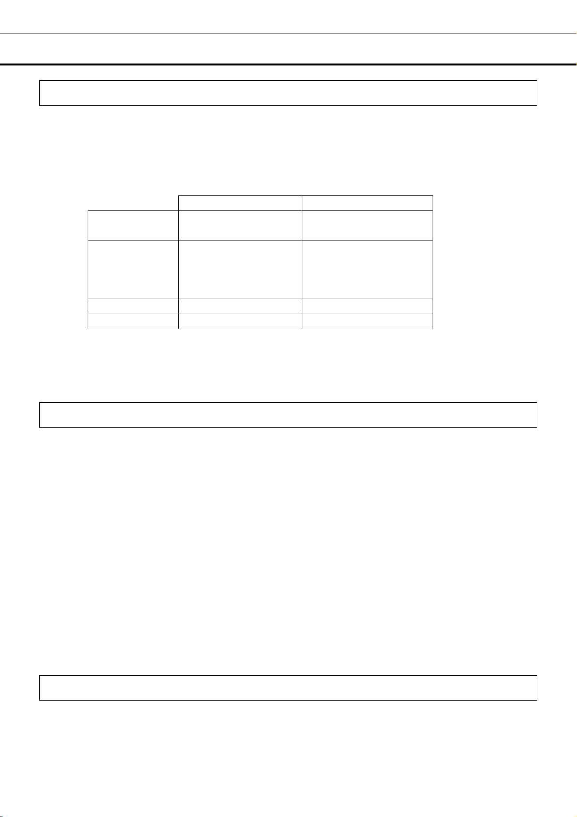
OPTIONAL COMPONENTS
Temperature recorder
The chamber temperature can be recorded and checked by installing an optional temperature recorder
MTR-85H or MTR-G85C.
Contact our sales representative or agent for the purchase of temperature recorder.
MTR-85H MTR-G85C
Recording
range
Feed speed of
recording paper
Recording paper Strip type Circular type
Power source Dry cell Supplied from the unit
For the installation of temperature recorder MTR-85H, an optional recorder fixing MDF-S3085 and recorder
sensor cover MTR-DU700SF is necessary.
For the installation of temperature recorder MTR-G85C, an optional recorder sensor cover MTR-DU700SF is
necessary.
Main specifications of temperature recorder
o
-100
C~+50 oC -100
2-month/batch
o
C~+40 oC
1-day/1 turn,
7-day/1 turn
32-day/1 turn
changeable
Small inner doors
For MDF-DU502VH, small inner doors (MDF-5ID4 (4 doors), MDF-5ID5 (5 doors)) are available as an
optional component.
For MDF-DU702VH, small inner doors (MDF-7ID4 (4 doors), MDF-7ID5 (5 doors)) are available as an
optional component.
For the installation, contact our sales representative or agent.
Note:
The cooling performance stated on page 58 cannot be guaranteed when the small inner doors are
installed.
o
Cooling performance : -82
For stable long-term use, we recommend setting it to + 5
temperature.
If you attach the small inner doors (MDF-5ID5, MDF-7ID5), you can not use the inventory racks
(IR-224U, IR-316U).
C at the center of the chamber (ambient temperature; 30 oC, no load)
o
C degrees from the minimum attained
Inventory rack
Optional inventory racks (IR-224U, IR-316U) are useful to store important items in the chamber effectively.
When these racks are used, it is necessary to change the location of the shelves.
Contact our sales representative or agent to arrange purchase of an inventory rack.
55

OPTIONAL COMPONENTS
Back-up cooling kit
By installing an optional backup cooling kit MDF-UB7 and a liquid CO
the chamber prevent to rise the chamber temperature for a few hours, even when this unit stops
operation by a power failure and so on.
Contact our sales representative or agent for the purchase of backup cooling kit.
cylinder, liquid CO2 injection into
2
WARNING
As with any equipment that uses CO
gas, there is a likelihood of oxygen depletion in the vicinity
2
of the equipment. It is important that you assess the work site to endure there is suitable and
sufficient ventilation. If restricted ventilation is suspected, then other methods of ensuring a safe
environment must be considered. These may include atmosphere monitoring and warning
devices.
The injection set temperature of the backup cooling kit can be set by the temperature setting knob [page
11]. Since the control method of injection is ON/OFF type, the actual injection temperature deviates from
the injection set temperature.
Note:
• Set the injection set temperature of the backup cooling kit to 10
Otherwise, continuous injection of liquid CO
may reduce the retention time of liquid CO2 cylinder.
2
• When the injection set temperature of the backup cooling kit is -70
ON: -67
o
C~-65 oC, OFF: -75 oC~-74 oC.
o
C higher than the set temperature.
o
C;
The behavior of the backup cooling kit
Backup
power switch
[Page 11]
Backup
display
[Page 12]
Condition of the
backup cooling kit
Chamber temperature Liquid CO
2
Less than the injection set
ON Switch ON Ready to inject
temperature of the backup
cooling kit.
The injection set temperature
of the backup cooling kit or
Does not inject
Injects
higher.
Less than the injection set
Not ready to inject
OFF Switch OFF
(Not ready to activate
the backup test switch)
temperature of the backup
cooling kit.
The injection set temperature
of the backup cooling kit or
Does not inject
higher.
• Duration of backup cooling:
MDF-DU502VH : Approx. 10 hours, MDF-DU702VH : Approx. 9 hours,
(ambient temp.; 30
o
C, set temp.; -70 oC, no load, liquid CO2 gas cylinder of 30 kg)
56

SPECIFICATIONS
g
g
Product name
External dimensions
Internal dimensions
Effective capacity
Exterior
Interior
Outer door
Inner door
Shelf
Access port
Insulation
Compressor
Evaporator
Condenser
Refrigerant
Temperature controller
Temperature display
Thermal sensor
Alarm
Remote alarm contact
Battery
Weight
Accessories
Optional component
Ultra-Low Temperature Freezer
MDF-DU502VH
W790 mm x D882 mm x H1993 mm W1030 mm x D882 mm x H1993 mm
W630 mm x D600 mm x H1400 mm W870 mm x D600 mm x H1400 mm
528 L 729 L
Painted steel
Painted steel
Painted steel
2 doors
Stainless steel, 3 shelves (adjustable)
Inner dimension; W615 mm x D534 mm
Load; Max. 50 k
Inner diameter: 17 mm, 3 locations (back x 1, bottom x 2)
Rigid polyurethane foamed-in place + Vacuum insulation panel
High stage side; Cascade type, Low stage side; Tube on sheet type
High stage side; Fin and tube type, Low stage side; Shell and tube type
High Alarm, Low Alarm, Power failure alarm, Door alarm, Filter alarm, Remote alarm
Lead storage battery, DC 6 V, 7200 mAh, Auto-recharge
246 kg 278 kg
1 set of key, 1 scraper, 1 stick for air intake port cleaning
Temperature recorder (MTR-85H, MTR-G85C)
Recorder fixing (MDF-S3085; MTR-85H)
Recorder sensor cover (MTR-DU700SF)
Backup cooling kit (MDF-UB7); For Liquid CO
Small inner door (MDF-5ID4, MDF-5ID5) Small inner door (MDF-7ID4, MDF-7ID5)
Drawers (MDF-50R) ―
Storage rack (MDF-70SC)
Inventory rack (IR-224U, IR-316U)
Interface board (MTR-L03) *1, *2; For LAN
Interface board (MTR-480) *1, *2; For RS-232C/RS-485
/shelf
High stage side; Output; 750 W
Low sta
High stage side; R-290, Low stage side; R-170
Microcomputer control system
Platinum resistance (Pt 1000 Ω)
Allowable contact capacity: DC 30 V, 2 A *1
e side; Output; 750 W
LCD Digital display
Ultra-Low Temperature Freezer
MDF-DU702VH
Stainless steel, 3 shelves (adjustable)
Inner dimension; W855 mm x D534 mm
Load; Max. 50 kg/shelf
2
*1: It is recommended to use standard signal and interface cables with a maximum length of 30 meters.
*2: For the data acquisition system MTR-5000 user only. Contact our sales representative or agent for purchase.
Note:
• Design or specifications are subject to change without notice.
• Refer to the updated catalogue when ordering an optional component.
57

PERFORMANCE
Product name
Model number
Cooling performance
Ultra-Low Temperature Freezer
MDF-DU502VH
MDF-DU502VH-PA MDF-DU702VH-PA
o
C at the center of the chamber (ambient temperature; 30 oC, no load)*
-86
Temperature settable range
Temperature control range
-86
Rated voltage
Rated frequency
Rated power consumption
430 W (Max. 820W) 550 W (Max. 930 W)
Noise level
Maximum pressure
Usable environment condition
Temperature; 5
* Maximum cooling performance.
The chamber temperature can be reached at -86
o
C to -50 oC
-90
o
C to -50 oC (ambient temperature; 30 oC, no load)
AC 220 V
60 Hz
52 dB [A] (background noise; 20 dB)
2200 kPa 2200 kPa
o
C to 30 oC Humidity; equal or less than 80 %R.H.
o
C at ambient temperature 30 oC with no load.
Ultra-Low Temperature Freezer
MDF-DU702VH
58

CAUTION
Please fill in this form before servicing.
Hand over this form to the service engineer to keep for his and your safety.
Safety check sheet
1. Freezer contents :
Risk of infection:
Risk of toxicity:
Risk from radioactive sources:
(List all potentially hazardous materials that have been stored in this unit.)
Notes :
2.
Contamination of the unit
Unit interior
No contamination
Decontaminated
Contaminated
Others:
3. Instructions for safe repair/maintenance/disposal of the unit
a) The unit is safe to work on
b) There is some danger (see below)
Procedure to be adhered to in order to reduce safety risk indicated in b) below.
Date :
Signature :
Address, Division :
Telephone :
□Yes □No
□Yes □No
□Yes □No
□Yes □No
□Yes □No
□Yes □No
□Yes □No
□Yes □No
Product name: Model: Serial number: Date of installation:
Ultra-low temperature MDF-
f
reezer
Please decontaminate the unit yourself before calling the service engineer.
59

1-1-1 Sakada, Oizumi-machi, Ora-gun, Gunma 370-0596, Japan
© PHC Corporation 2018
Printed in Japan
LDCL046500-0
S0418-0
 Loading...