

Page 1

ai
aiInstallation Guide
Page 2
ai
ai
Installation Guide
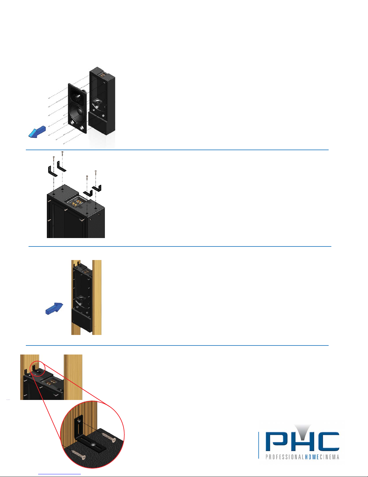
Step 1 - Remove Bae Assembly
1.1 - Remove the #10-24 machine screws holding the bae subassembly.
1.2 - Disconnect the white wire connector and remove the bae subassembly.
1.3 - Reinsert the machines screws into the enclosure for safe keeping.
1.4 - Store bae assembly for safe keeping until home construction is complete.
Step 2 - Attach Brackets
2.1 - Using the #10-24 x 1.25” screws already installed in the top of the enclosure, install
four PHC mounting brackerts as shown.
2.2 - The slots in the brackets allow you to adjust them for the correct spacing between
studs - usually 14.5”. Adjust the brackets to slightly less than the desired dimension.
2.3 - Repeat this procedure on the bottom surface of the loudspeaker.
NOTE: ai models have bracket mount screw locations on enclosure sides and front (the
same screws that secure the speaker bae) to facilitate mounting in orientations other
than shown here.
Step 3 - Position Speaker
3.1 - With help from others, and using temporary supporting members if necessary, carefully move the speaker enclosure into position between the wall studs.
Use wood construction shims if necessary to center the speaker between the
studs and to provide additional support during mounting.
3.2 - Once the enclosure is in place, loosen the bracket mounting screws and
adjust the brackets to t at against the stud surface, then tighten screws
securely.
CAUTION: Failure to get a at and tight t between the bracket and stud surface
will result in weak installation and possible bracket failure.
Step 4 - Anchor Brackets to Studs
4.1 - Using the #10 x 1.25” lag screws provided, achor the speaker to the studs
using the countersuck holes nearest the bracket end.
4.2 - For additional support, #10 pan or truss head lag screws may also be
installed in through the slots below the countersunk holes.
Professional Home Cinema, LLC
5445 Oceanus Drive, Suite 110
Huntington Beach, CA 92649
Tel: 800-272-6085 Fax: 714-890-0536
www.professionalhomecinema.com
Page 3
ai
ai
To amplier negative
TWEETER output
Installation Guide
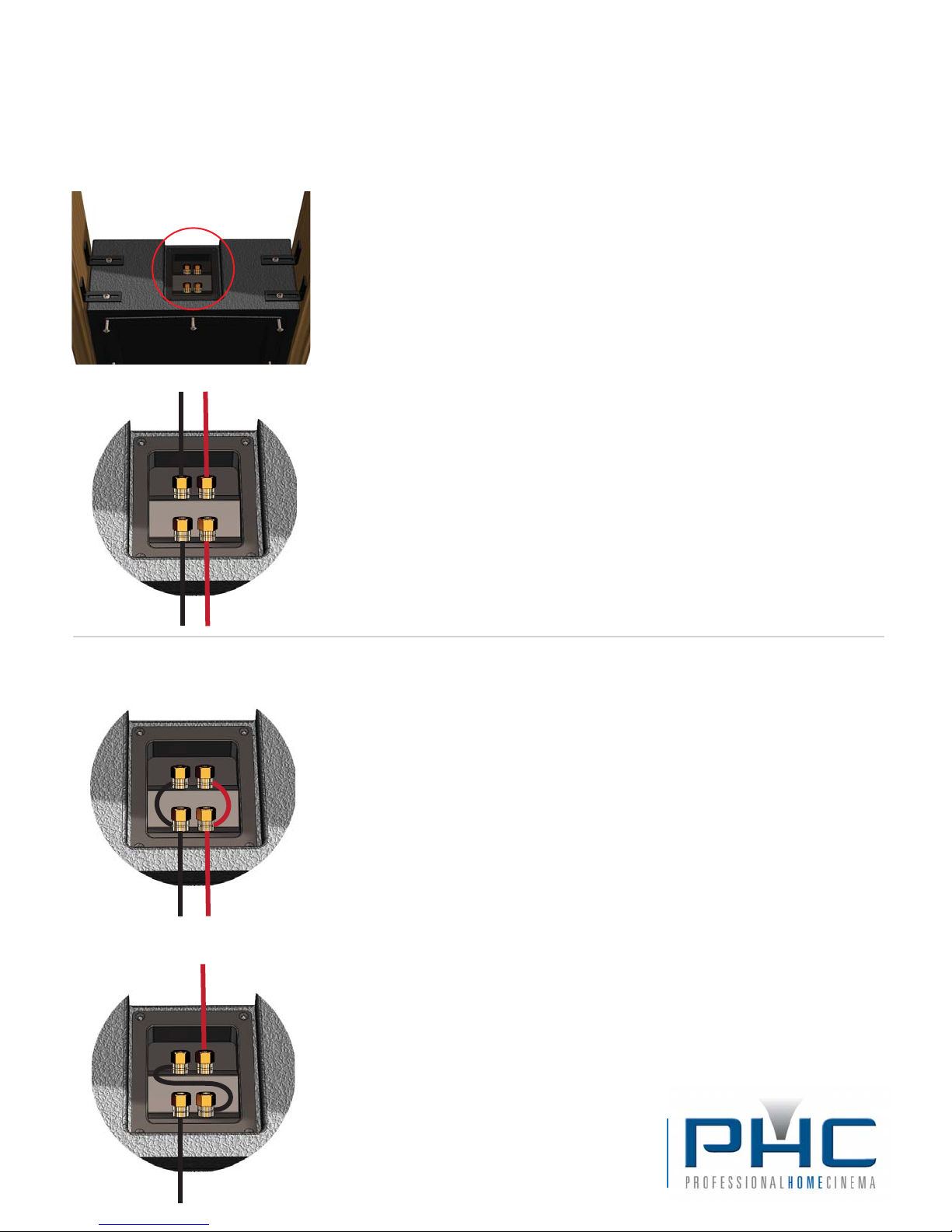
Step 5 - Connect Speaker Wires
TWO-WAY ai MODELS:
All ai two-way loudspeakers require bi-amplication and therefore have four
input terminals. Within the terminal cup, the upper set of binding posts are the
inputs for the tweeter, and the lower set are the inputs for the woofer (when
To amplier positive
TWEETER output
viewing the cup from the front of the speaker).
5.1 - Connect the upper binding posts to the PHC amplier channel congured
for high-pass (tweeter) processing for the model being installed. Be sure to
observe correct polarity and connect ONLY to amplier with DSP programming
for your ai model. Connection to an amplier with incorrect DSP program could
result in loudspeaker damage.
5.2 - Connect the lower set of binding posts to the PHC amplier channel
congured for low-pass (woofer) processing for the model being installed.
Again, observe correct polarity and double-check DSP programming.
To amplier negative
WOOFER output
4-ohms
To amplier
woofer output
16-ohms
negative
To amplier positive
WOOFER output
To amplier
positive woofer
output
To amplier
positive woofer
output
SUBWOOFER ai MODELS:
The ai subwoofer model has four input terminals located on the woofer-end of
the long enclosure. The subwoofer employs two woofers - each of which is
connected to its own set of input posts, and each has a nominal impedance of
8-ohms. This allows exibility of system design since by altering the wiring
methodology one can acheive impedances of 4 and 16 ohms depending on
need. Maximum power is transferred from PHC ampliers when the load on any
channel is 4-ohms. The 16-ohm conguration is useful when you want to run
many woofer boxes on one amplier channel: 4 ai woofer enclosures wired for
16 ohms may be paralleled for a nal impedance of 4 ohms, for example,
allowing a single amp channel to drive four subwoofer enclosures. Power to
each enclosure is shared equally (ex: 1000W total/4 enclosures = 250W per
enclosure).
5.1 Connect the subwoofer input terminals as shown in the diagrams to the left
using the conguration that provides the nal load impedance desired.
CAUTION: Never load any PHC amplier model channel with nominal nal total
impedance of less than 4-ohms. Otherwise, amplier damage may result.
To amplier
negative
woofer output
Professional Home Cinema, LLC
5445 Oceanus Drive, Suite 110
Huntington Beach, CA 92649
Tel: 800-272-6085 Fax: 714-890-0536
www.professionalhomecinema.com
Page 4
ai
ai
Installation Guide
AFTER CONSTRUCTION IS COMPLETE
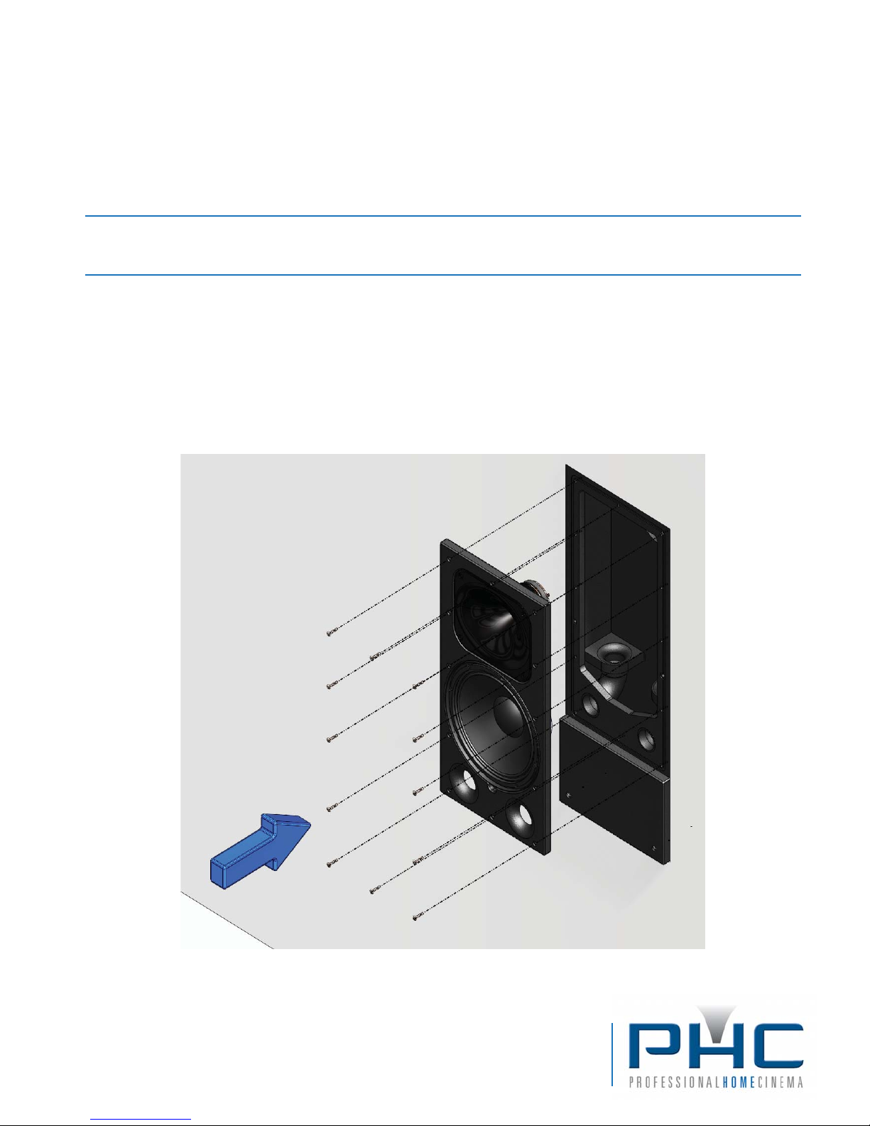
Step 6 - Reinstall Bae Assembly
6.1 - Remove the #10-24 machine screws installed in the enclosure front.
6.2 - Reconnect the white wire harness connector.
6.3 - Reinstall the bae assembly and secure it using the #10-24 machine screws.
Tighten screws uniformly to insure an air-tight seal between bae and enclosure.
Professional Home Cinema, LLC
5445 Oceanus Drive, Suite 110
Huntington Beach, CA 92649
Tel: 800-272-6085 Fax: 714-890-0536
www.professionalhomecinema.com
 Loading...