

Page 1
User Guide
Model PMB-RL6 Remote Relay Box
Description
PHAST Remote Boxes are compact units that can be placed anywhere in a home, extending the
connectivity of the Landmark system while eliminating many long runs of control cable to PHAST
Hubs or MCUs. Remote Boxes communicate with the Landmark system via the PHASTLink data
bus, using one of the two RJ-45 ports on the rear panel. The other RJ-45 port can be used for
daisy-chaining additional devices.
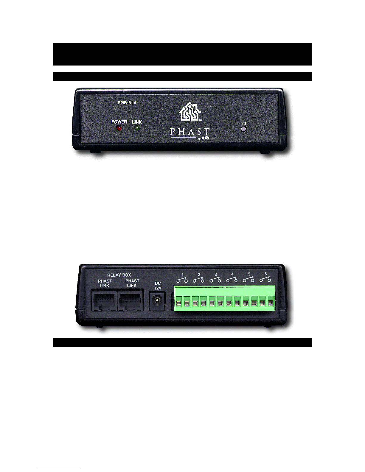
The PMB-RL6 Remote Relay Box contains six dry-contact relays for controlling external devices,
such as screens, drapes, video lifts, and other closure-control equipment. Relays can be set to
normally open or normally closed with internal jumpers. Connection to external devices is via
screw-down Phoenix connectors on the rear panel. All Remote Boxes come with a 12VDC power
supply.
LEDs on the front panel indicate power and link status. An ID button provides ID information to
the Landmark system that facilitates easy connection of the physical Remote Contact Box with
the correct Remote Contact Box in software.
Specifications
• Relays 6 dry-contact relays. Can be set to normally open or normally closed via
jumpers.
Relays are each rated 1 Amp @ 30VDC.
• Network 2 RJ-45 PHASTLink ports, both functionally identical. Allows daisy chaining.
• Power 12VDC, 1 Amp power supply (included).
• Indicators Power, Link LEDs on front panel.
• ID Data ID button on front panel sends ID information for setup.
• Height 1.5 in. (38 mm)
• Width 5.1 in. (130 mm)
• Depth 5.1 in. (130 mm)
Page 1 of 2 08/07/00
Page 2
• Weight 7.7 oz. (218 g)
Installation and Operation
Caution:
Many electronic components are static sensitive. If possible, install these components in a
static-free work environment. Otherwise, touch a grounded metal object to discharge any static
charge before handling these components. Do not touch any live electrical conductors.
1. Check the RJ-45 connector(s) and wiring for proper function.
2. Plug the RJ-45 connector(s) into the RJ-45 socket(s) on the rear panel. It does not matter
which RJ-45 socket(s) you use.
3. Connect the leads from up to six external closure-control devices to the appropriate
connectors on the rear panel.
4. Insert the 12VDC power supply plug into the DC 12V receptacle on the rear panel.
5. Plug the power supply into a properly grounded 120VAC outlet. The Power LED on the front
panel should be illuminated.
6. When configuring the system, press the ID button on the front panel to send device ID
information to the Landmark system. This allows you to make the correct software
connection to this physical device.
7. The Link LED flashes when data is sent from the contact box regarding a change of a relay
state, when a command to get the state of the relays is sent to the box from the Landmark
system, and when an ID signal is sent to the box from the Landmark system.
Technical Support
If you experience problems with your PHAST products, double check all external connections,
settings, and power sources before contacting your PHAST dealer or PHAST Corporation.
• If the problem persists, call your PHAST dealer or PHAST Technical Support.
• Write your PHAST dealer's number here for easy
reference:___________________________
• You can contact PHAST Technical Support at 800-979-9637 or 801-264-8090.
• Support is also available at the PHAST web site at http://phast.com
PHAST Corporation
79 West 4500 South, Building 14
Salt Lake City, Utah 84107
801-264-8090
800-979-9637
801-264-8271 FAX
Page 2 of 2 08/07/00
Page 3

http://phast.com
Page 3 of 2 08/07/00
 Loading...