

Page 1
T E C H N O L O G Y
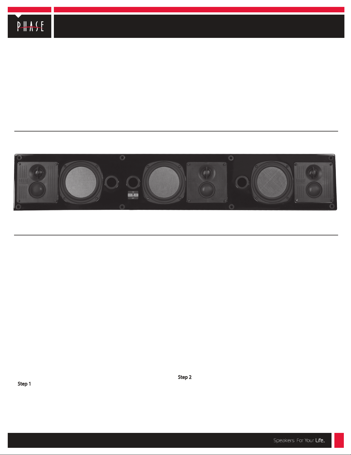
Install instructions for TEATRO Soundbar models:
T-PC3.0
Thank you for purchasing the Phase Technology TEATRO LCR high
denition at panel sound bar speaker system. The TEATRO sound
bar speaker’s Left-Center Right conguration with Phase
Technology’s Enhanced Voice Technology, EVT™ center channel
design and Spatial Field Expander, SFE™ enable the speaker to
provide outstanding dialogue clarity for movies with an open, wide
sound stage normally obtained with separate component speaker
systems.
The TEATRO sound bar speakers are a compact design made
to t under at panel TV’s. For “on wall” applications they come with a
mounting bracket that has adjustments for lining up and vertically
leveling the speaker with the at panel TV. There are also threaded
inserts located on the rear of the cabinet for applications where
mounting the speakers to a display wall bracket mechanism is
required.
Note: Please check with the mount manufacture for compatibility if
you are using a at panel display mount that includes speaker mounting brackets. Check the specications for total weight limitations and
make sure it will support a sound bar speaker of between 25-30 Lbs.
CAUTION: BE VERY CAREFUL NOT TO DAMAGE THE MIDRANGE
DOMES OR SFE DRIVERS (LOCATED ON THE SIDES OF THE CABINET)
WHILE HANDLING THE TEATRO PC-3.0.
When selecting the speaker mounting location, it is prudent to take a
few extra minutes to carefully inspect and measure the wall where
you intend to mount the TEATRO sound bar speakers and your at
panel display. An inspection of the room or rooms that back up to the
wall you have selected for mounting the TEATRO can often alert you
to potential obstacles. For example, if the wall you want to mount to
happens to be the common wall for a bathroom or kitchen, there is a
good chance you will encounter water or sewer pipes in the wall that
will not be detected by a stud-nder. An electronic stud-nder is a
useful tool to assist you in selecting the speaker placement, but be
cautious as they often give false readings. It is recommended that
wherever possible you try to fasten these mounting brackets to a
vertical stud with the appropriate wood screws. If it is not possible to
mount the brackets over the studs then it is recommended that the
appropriate hollow wall anchors or toggle bolts be used to mount the
TEATRO. Be certain to use at least four of the mounting holes on each
bracket to assure a safe and reliable installation.
Note: to take full advantage of Phase Technology’s Spatial Field
Expander (SFE™), please try to mount the speaker so that the sides of
the speaker cabinet are not obstructed.
Step 1
Determine that the desired mounting location is safe and clear of any
physical obstructions that might hinder the proper installation of the
speakers. If the at panel monitor is already installed on the wall you
can use it as a guide for the installation of the speakers. For the best
appearance it is recommended that the speaker be installed
symmetrically beneath the monitor. The spacing from the monitor is
not critical so you may use whatever is most appealing aesthetically
but the speakers’ response characteristics will be best if you stay
within a few inches of the display.
Special consideration must be taken to run three (3) sets of speaker
leads to the TEATRO sound bar speakers. One pair each will be
connected to the left and right channel on your amplier and the
other pair will be used for the center channel. Be certain that you can
get the speaker wire to the locations where you plan to mount the
speaker systems.
Please note that the TEATRO sound bar speakers are designed to
mount very close to the wall and the brackets only allow about 1” of
clearance so be certain to make allowances for this with your speaker
connectors and wire clearances.
We suggest that you use a minimum of AWG #16 wire. Pre-run your
speaker wire to the determined locations and be certain to leave
about two feet of extra wire for the nal speaker installation. If the at
panel monitor is not yet mounted to the wall, mount the display rst
before mounting the speakers.
Step 2
Normal mounting for the TEATRO sound bar speaker is centered
directly below the display. Both the speaker and the brackets have a
series of holes that allow for exibility in mounting. The brackets can
also slide inside each other for left/right positioning adjustments. The
holes in the brackets allow them to be positioned for attaching to 16”
on center studs. There are four identical brackets supplied with the
speaker. Two are mounted to the wall, two are mounted to the rear of
the speaker cabinet.
218-2082
Page 2
Install instructions for TEATRO Soundbar models, Page 2
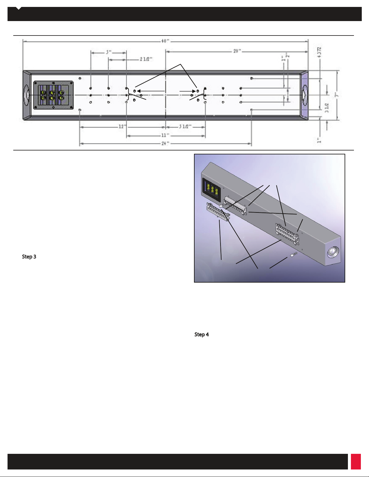
FLAT PANEL WALL MOUNT
8 3/16”
USE THESE SETS OF HOLES
FOR SPEAKER BRACKETS FOR
NORMAL WALL MOUNTING
Figure 1
Measure your at panel display horizontally and nd the center
(width). The brackets should be positioned 5” either side of this center
line. Using the mounting bracket as a guide, measure 1 ½” from the
bottom of the display to the top edge of the bracket and 5” over from
the center line to the bracket edge (see Fig. 1). This will allow about a
¼” space between the bottom of the display and the speaker cabinet.
This spacing can be adjusted to suit personal taste or applications as
necessary. Use a level to make sure the mounting bracket is straight.
With the bracket positioned in the desired location use a pencil to
mark at least four mounting holes on the wall for the bracket mounting screws. Try to have at least 2 holes on each bracket that line up
over a wall stud. Drill the wall, install your anchors and fasten the
brackets to the wall with the “J” bend at the bottom (g. 2 & 3).
ATTACHMENT INSERTS
SPEAKER MOUNTING BRACKETS
HOOK INTO WALL BRACKETS
SPEAKER MOUNT
BRACKETS
Step 3
Place your TEATRO sound bar speaker face down on a soft clean
surface with the grille on. Orient the speaker so the input terminal is
on the left hand side. The second pair of steel brackets supplied with
the speaker is designed to attach to the threaded inserts on the rear of
the speaker cabinet with the eight supplied #10-32x3/8” Philips
screws. Align the holes on the brackets with the center and bottom set
of mounting holes on the rear of the speaker. Position the brackets
similar to the ones mounted on the wall with the “J” bend up so it can
hook into the wall bracket. Attach brackets to the rear of the speaker
using four screws per bracket (Fig. 1 & 2).
Install one each of the 6, #10-32x1” Phillips screws in the threaded nut
located in the bottom center of the “J” bend of the two wall mounted
brackets. These screws are for leveling the speaker. Start the screws,
but do not screw in at this time.
Install the other four 1” screws in the end mounted nuts of the cabinet
mounted brackets. These are the bracket locking screws and should
be installed so they can be adjusted from the bottom of the speaker
(Fig. 3 next page).
Assemble the two rubber stand-o bumpers next. Thread one nut
onto each bumper stand-o and then one nylon washer. Run the nut
about halfway down the screw. Thread each of the bumper stand-os
into the two lower inserts located on the bottom rear edge of the
cabinet (Fig. 2).
WALL MOUNT
BRACKETS
STAND-OFF BUMPER
LOCK NUT, WASHER
Figure 2
Step 4
There are three pair of gold binding post terminals on the rear of the
speaker cabinet. The terminals are marked for Right Input, Center
Input and Left Input and should be connected to the respective
speaker channel outputs on your receiver. Connect the speaker wires
to the correct terminals observing the polarity indicated on the
terminal. Red is + or positive and black is – or negative. Strip about ½”
of insulation from the wires and separate the wires as necessary. If you
are using other wire lugs or connectors, attach them at this time to the
bare wire. Unscrew the binding post terminals and slip the stripped
end of the wire through the hole in the metal post. Secure the wire in
the post by tightening the binding post terminal nut down on the
bare wire or lug. Make sure the nut is tight and the wire will not pull
out of the terminal by lightly pulling back on the wire. Tuck the
speaker wire in behind the speaker cabinet; if necessary, neaten up
the wire with the use of tie wraps.
8005 W. 110th St., Suite 208 / Overland Park, KS 66215 / (888)PHASE TK / www.phasetech.com / www.mseaudio.com
Page 3

Install instructions for TEATRO Soundbar models, Page 3
Step 5
The TEATRO sound bar speaker is now ready to be mounted to the
brackets that were screwed to the wall in step 2. The brackets are
made to interlock with each other. Raise the speaker so the brackets
on the rear of the cabinet are aligned with the wall brackets and
engage the “J” bends in the two sets of brackets together. If the
speaker is being installed very close to the bottom of the at panel
display the speaker brackets can be slid into each other from the side.
After the brackets are interlocked, it is a simple matter to center the
speaker by sliding it side to side. The speaker can also be leveled by
turning in the appropriate height adjusting screw to raise and lower
the ends of the speaker. This is done with a #2 Phillips screwdriver
from the bottom side of the bracket. Once the speaker position is
trimmed up it should be locked in place using the 4 locking screws in
the speaker bracket (Fig. 3). Be careful not to over-tighten the screws.
WALL MOUNTING BRACKET
LEVELING ADJUSTMENT SCREW
IN WALL BRACKET
Adjust the rubber stand-o bumpers by turning them either in or out
to adjust the tilt of the speaker until the front is vertical. Lock the
adjusting screws in place by tightening the locking nuts against the
rear of the cabinet. Make certain the nylon washer is between the nut
and the cabinet to protect the cabinet nish.
Step 6
Since the TEATRO sound bar speakers perform as the front three
speakers in a home theater system they are to be used and set up as
you would any normal 5.1 to 7.2 surround sound system for balance
and level adjustments. For the best performance, the amplier should
be set to the small speaker mode for the left/center/right front speakers. The subwoofer setting should be set to 80 Hz. We recommend the
use of our Phase Technology subwoofers and surround speakers to
complement your TEATRO Soundbar.
Step 7
The EVT™ switch (Fig. 4), located on the front of the speaker under the
grille, activates Phase Technology’s Enhanced Voice Technology
feature. This feature is designed to improve the clarity of the voice or
dialogue from the center channel speakers in the system. Flipping the
switch to the up position engages the circuit and down turns it o.
TEATRO SOUND BAR SPEAKER SPECIFICATIONS
MODEL
TWEETER
MIDRANGE
WOOFER
FREQUENCY
SENSITIVITY
IMPEDANCE
MAXIMUM POWER
DIMENSIONS
FINISH
WEIGHT
T-V3.0 T-PC3.0
1” SOFT DOME x 3 1” SOFT DOME x 3
----- 1.5” SOFT DOME x 3
5.25” VDT x 3 5.25” RPF x 3
55Hz-22kHz 52hz-22kHz
91 dB 89 dB
4 OHMS 4 OHMS
120 WATTS 150 WATTS
40” (W) x 7” (H) x 4
SATIN BLACK GLOSS BLACK
25 LBS 30 LBS
SPEAKER MOUNTING BRACKET
LOCKING SCREWS IN
SPEAKER BRACKET
Figure 3
Figure 4
Mounting To Flat Panel Mounting Brackets
There are additional mounting inserts on the rear of the speaker
cabinet to facilitate at panel mounts (see note on Figure 1). There are
six threaded inserts provided that coincide with the requirements of
most manufacturers’ mounts. Please check with your Phase Technology dealer for appropriate mounts and compatibility.
” (D) (5 ” with bracket)
6400 Youngerman Circle / Jacksonville, FL 32244 / (888)PHASE TK / www.phasetech.com
Page 4

Install instructions for TEATRO Soundbar models, Page 4
SAFETY INSTRUCTIONS
CAUTION: To reduce the risk of electric shock, do not remove cover (or
personnel.
Explanation of Graphical Symbols
!
1. Read Instructions - All the safety and operating
instructions should be read before the appliance is
operated.
2. Retain I nstructio ns - The safety and operating
instructions should be retained for future reference.
3. Heed Warnings - All warnings on the appliance and in
the operating instructions should be adhered to.
4. Follow Instructions - All operating and other
instructions should be followed.
5. Water and Moisture - The appliance should not be
used near water - for example, near a bathtub, washbowl,
kitchen sink, laundry tub, in a wet basement, or near a
swimming pool, etc.
6. Carts and Stands - The appliance should be used
only with a cart or stand that is recommended by the
manufacturer.
PORTABLE CART WARNING
CAUTION
RISK OF ELECTRIC SHOCK
DO NOT OPEN
equilateral triangle, is intended to alert you to the
presence of un-insulated “dangerous voltage: within the
to constitute a risk of electric shock to persons.
The exclamation point within an equilateral triangle
is intended to alert you to the presence of important
operating and maintenance (servicing) instructions in the
literature accompanying the appliance.
!
9. Heat - The appliance should be situated away
from heat sources such as radiators, stoves, or other
appliances that produce heat.
10. Power Source - The appliance should be connected
to a power supply only of the type described in the
operating instructions or as marked on the appliance.
11. Power Cord Protection - Power supply cords should
be routed so that they are not likely to be walked on
or pinched by items placed up or against them, paying
particular attention to cords at plugs, convenience
receptacles, and the point where they exit from the
appliance.
12. Cleaning - The appliance should be cleaned only as
recommended by the manufacturer.
13. Nonuse Periods - The power cord of the appliance
should be unplugged from the outlet when left unused
for a long period of time.
14. Object and Liquid Entry - Care should be taken so
that neither objects fall nor liquids spill into the inside of
the appliance.
15. Damage Requiring Service - The application should
a. the power supply cord or the plug has been damaged,
b. Objects have fallen onto or liquid has been spilled into
the appliance,
c. the appliance has been exposed to rain,
d. the appliance does not appear to operate normally or
exhibits a marked change in performance, or
e. the appliance has been dropped or the cabinet
damaged.
16. Servicing - The user should not attempt to service
the appliance beyond those means described in the
operating instructions. All other servicing should be
17. Grounding or Polarization - Precautions should be
taken so that the grounding or polarization means of an
appliance is not defeated.
7. Wall or Ceiling Mounting - The appliance should be
mounted to a wall or ceiling only as recommended by the
manufacturer.
8. Ventilation - The appliance should be situated so
that its location or position does not interfere with its
proper ventilation. For example, the appliance should not
be situated on a bed, sofa, rug, or similar surface that
may block the ventilation openings; or placed in a builtin installation, such as a bookcase or cabinet that may
8005 W. 110th St., Suite 208 / Overland Park, KS 66215 / (888)PHASE TK / www.phasetech.com / www.mseaudio.com
APPLICABLE FOR USA, CANADA OR WHERE APPROVED
FOR USAGE
CAUTION: TO PREVENT ELECTRIC SHOCK, MATCH WIDE BLADE
PLUG TO WIDE SLOT, INSERT FULLY.
ATTENTION: POUR EVITER LES CHOCS ELECTRIQUES,
INTRODUIRE LA LAME LA PLUS LARGE DE LA FICHE DANS LA
BORNE CORRESPONDANTE DE LA PRESE ET POUSSER JUSQU
AU FOND.
 Loading...