

Page 1
TE CH NO LO GY
R
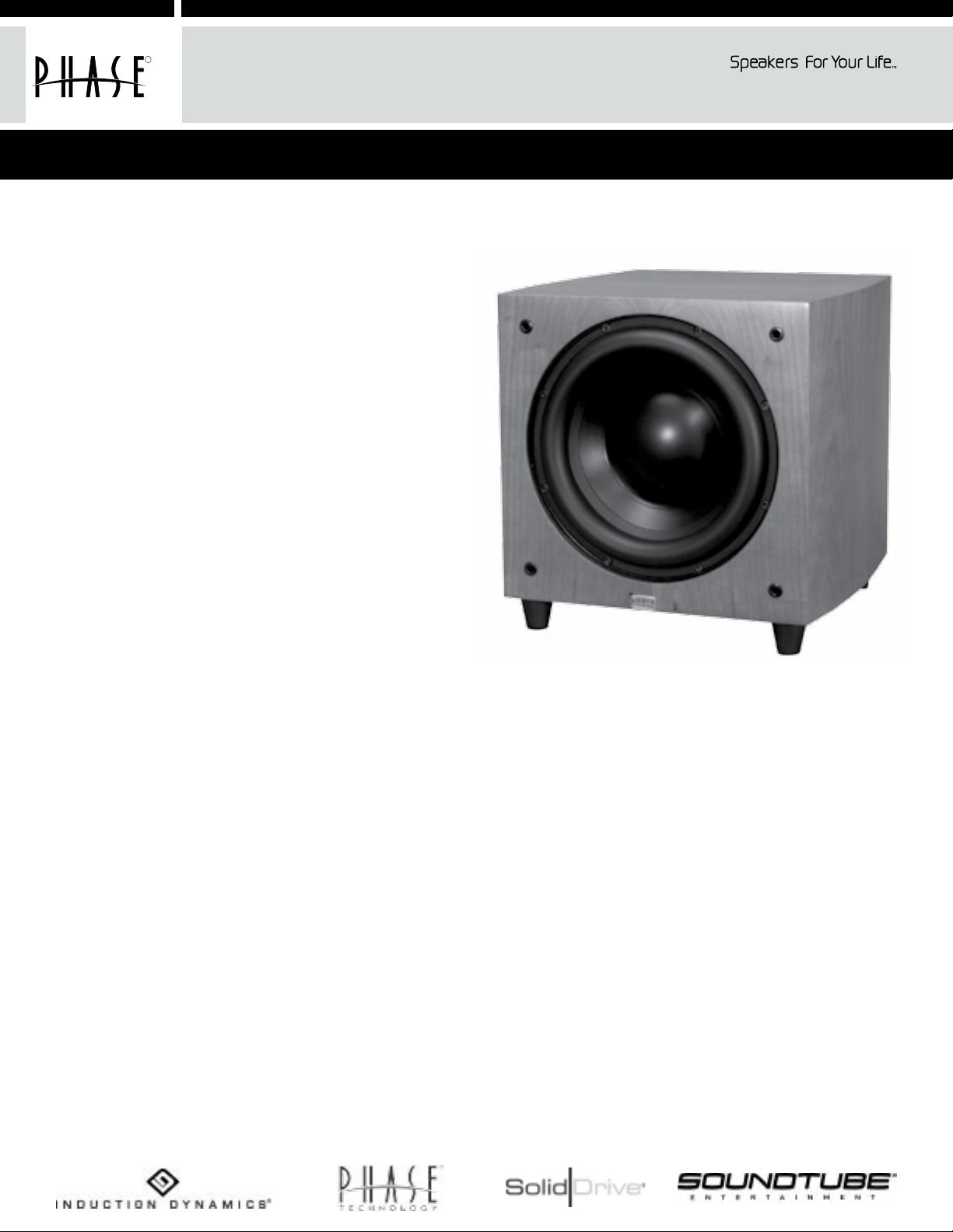
PC-SUB WL Subwoofers
Owners Manual / Installation Instructions
Thank you for choosing Phase Technology speakers. We know there are a wide variety of choices available today, and
we sincerely appreciate your purchase of our product. Phase Technology speakers are built to exacting standards and
will provide many years of listening enjoyment.
Our speakers are the result of over ve decades of
designing and manufacturing what many consider
the nest sound reproduction products available. We
hold several key patents in loudspeaker technology,
including the soft-dome tweeter. Our mission, our
passion is to constantly advance the art and science
of accurate audio reproduction. Our dedication
insures your new speakers will accurately reproduce
all the impact, detail and delicacy of today’s digital
technology.
Regardless of application, serious audiophile listening
or home theater, we recommend that you take the
time to read this manual thoroughly before connecting
speakers to your amplier or receiver. In the highly
unlikely event that you should experience a problem
with set-up or operation, please contact one of our
carefully chosen dealers for assistance, or contact us
directly.
Power FL-8 Power FL-10 Power FL-12
PC-SUB WL-8 PC-SUB WL-10 PC-SUB WL-12
PC-SUB WL-10
We trust that your new Phase Technology subwoofers
will enrich your enjoyment of music and movies beyond
your expectations.
CONTENTS:
SAFETY PRECAUTIONS 2
PLACEMENT 3
HOOKING UP YOUR PC-SUB WL SUBWOOFER 3
PC-SUB WL SERIES AMPLIFIER PANEL 4
VIBRATION ISOLATION PADS 4
SPECIFICATIONS 4
Phase Technology 8650 College Boulevard Overland Park, Kansas 66210 (866) 663-9770 www.phasetech.com
An MSE Audio Group company www.mseaudio.com
PC-SUB WL SERIES FEATURES:
• 300 watt RMS, 900 watt peak power internal
amplier
• Signal sensing auto turn on/off
• Gain control
• Phase switch
• Variable crossover
• Wireless 2.4 GHz uncompressed audio streaming
• Line/LFE input
• Ultra long excursion woofers and passive radiators
• Servo-controlled amplier, which monitors and
adjusts output for dynamic and undistorted response
Page 2
SAFETY INSTRUCTIONS
PLACEMENT
CAUTION
RISK OF ELECTRIC SHOCK
DO NOT OPEN
CAUTION: To reduce the risk of electric shock, do not remove cover (or
back). No user-serviceable parts inside. Refer servicing to qualied service
personnel.
Explanation of Graphical Symbols
The lightning ash with arrowhead symbol, within an
equilateral triangle, is intended to alert you to the
presence of un-insulated “dangerous voltage: within the
product’s enclosure that may be of sufcient magnitude
to constitute a risk of electric shock to persons.
The exclamation point within an equilateral triangle
is intended to alert you to the presence of important
operating and maintenance (servicing) instructions in the
!
literature accompanying the appliance.
1. Read Instructions - All the safety and operating
instructions should be read before the appliance is operated.
2. Retain Instructions - The safety and operating
instructions should be retained for future reference.
3. Heed Warnings - All warnings on the appliance and in the
operating instructions should be adhered to.
4. Follow Instructions - All operating and other instructions
should be followed.
5. Water and Moisture - The appliance should not be used
near water - for example, near a bathtub, washbowl, kitchen
sink, laundry tub, in a wet basement, or near a swimming pool,
etc.
6. Carts and Stands - The appliance should be used only
with a cart or stand that is recommended by the manufacturer.
PORTABLE CART WARNING
7. Wall or Ceiling Mounting - The appliance should be
mounted to a wall or ceiling only as recommended by the
manufacturer.
8. Ventilation - The appliance should be situated so that
its location or position does not interfere with its proper
ventilation. For example, the appliance should not be situated
on a bed, sofa, rug, or similar surface that may block the
ventilation openings; or placed in a built-in installation, such as
a bookcase or cabinet that may impede the ow of air through
the ventilation openings.
9. Heat - The appliance should be situated away from heat
sources such as radiators, stoves, or other appliances that
produce heat.
!
10. Power Source - The appliance should be connected
to a power supply only of the type described in the operating
instructions or as marked on the appliance.
11. Power Cord Protection - Power supply cords
should be routed so that they are not likely to be walked
on or pinched by items placed up or against them, paying
particular attention to cords at plugs, convenience
receptacles, and the point where they exit from the
appliance.
12. Cleaning - The appliance should be cleaned only as
recommended by the manufacturer.
13. Nonuse Periods - The power cord of the appliance
should be unplugged from the outlet when left unused for a
long period of time.
14. Object and Liquid Entry - Care should be taken so
that neither objects fall nor liquids spill into the inside of the
appliance.
15. Damage Requiring Service - The application should
be serviced by qualied service personnel when:
a. the power supply cord or the plug has been damaged,
b. Objects have fallen onto or liquid has been spilled into the
appliance,
c. the appliance has been exposed to rain,
d. the appliance does not appear to operate normally or
exhibits a marked change in performance, or
e. the appliance has been dropped or the cabinet damaged.
16. Servicing - The user should not attempt to service the
appliance beyond those means described in the operating
instructions. All other servicing should be referred to qualied
service personnel.
17. Grounding or Polarization - Precautions should be
taken so that the grounding or polarization means of an
appliance is not defeated.
18. FCC Rules Part 15 Compliance - This device
complies with part 15 of the FCC rules. Operation is subject
to the following two conditions:
(1) This device may not cause harmful interference, and
(2) This device must accept any interference received,
including interference that may cause undesired operation.
Changes or modications not expressly approved by the party
responsible for compliance could void the user’s authority to
operate the equipment.
This Class B digital apparatus complies with Canadian ICES-
003.
Cet appareil numérique de la classe A est conforme à la
norme NMB-003 du Canada.
APPLICABLE FOR USA, CANADA OR WHERE APPROVED
FOR USAGE
CAUTION: TO PREVENT ELECTRIC SHOCK, MATCH WIDE BLADE PLUG TO
WIDE SLOT, INSERT FULLY.
ATTENTION: POUR EVITER LES CHOCS ELECTRIQUES, INTRODUIRE LA LAME
LA PLUS LARGE DE LA FICHE DANS LA BORNE CORRESPONDANTE DE LA
PRESE ET POUSSER JUSQU AU FOND.
Subwoofers offer the greatest variety of placement options since very low frequencies are essentially non-directional. That is, the human
ear cannot determine where low frequencies originate, thus, speaker placement is open to a wide variety of choices. By using the
wireless option, your PC-SUB WL subwoofer can be placed anywhere AC power is available within a 50-foot radius of the transmitter. It is
recommended that you place the subwoofer along the same wall as your front speakers. If using one subwoofer, a corner placement will
give you the most low frequency output. If using two subwoofers, start by placing them next to the front left and right speakers in both
front corners or one in the corner and one 1/3 of the way along the front wall from the corner. Each room is different. Experiment with
these options and try other locations until you get the best results.
HOOKING UP YOUR PC-SUB WL SUBWOOFER
Option 1: Wireless Setup
The PC-SUB WL wireless transmitter includes a power adapter. This power adapter is a universal adapter and is designed to operate on
household power of 100-240V and 50/60Hz. Plug the power adapter into a convenient power outlet and the small coaxial power plug
into the rear of the transmitter socket labeled “DC In +5V”. The transmitter should power up and display a blue LED light on the front of
the unit.
Next, connect the “SUB/Left IN” on the wireless transmitter to the “Subwoofer Out”, “SUB OUT”, or “Pre-Amp Out” connection on the
rear of your receiver or processor using a dedicated RCA interconnect cable. Plug the PC-SUB WL into a wall outlet and turn the power
switch on. The power LED should turn red and the Wireless Status LED should be blue. The transmitter and the subwoofer now need to
be synchronized (paired) so that they will recognize each other.
Transmitter / Receiver pairing instructions
Up to two PC-SUB WL Subwoofer systems can work in close proximity. When using two subwoofers each needs to be paired to its own
transmitter. Pairing is done as follows:
1. Press the RESET button for the receiver unit on the back of the subwoofer once. The blue LED will start blinking quickly.
2. Press the button located on the bottom of the transmitter unit once. The Blue LED will start blinking quickly. After a few seconds both
blue LEDs will stay on continuously. If pairing is not successful the blue LED on the Transmitter will start blinking slowly after 10 seconds.
In this case, press the button on the transmitter again.
Note: There is no need to press the receiver button again (the button on the back of the subwoofer). The ashing Receiver LED indicates
that the receiver is waiting for a transmitter to connect to it.
Two wireless PC-SUB WL subwoofers can be used simultaneously, but each requires its own transmitter. If you already have one system
installed, then repeat the above process but press the transmitter button on the second transmitter twice in order to avoid interference
with the rst system. Our wireless topology uses adaptive frequency hopping. If interference is detected the transmitter and receiver
automatically switch to another channel. If for some reason the pairing is interrupted then re-pairing will resolve the problem and return
the system to normal operation.
NOTE: Recommended wireless operating range is 50 feet. The range depends on usage and obstructions between the transmitter and
receiver.
Option 2: Wired Direct Connection Setup
This is the recommended (wired) method of connection for those applications where the Wireless Transmitter will not be used.
attempt to connect your PC-SUB WL using both the wired and wireless hookups.
Most A/V receivers and processors are equipped with a “Subwoofer Out” or “Pre-Amp Out” connection. Run a dedicated RCA interconnect
cable from the “SUB OUT” terminal on your receiver or amplier to the “LINE IN” terminal on the subwoofer.
Bass Management
Many home theater receivers/processors have a “Bass Management” feature that controls how the bass is processed and delivered to
the subwoofers. Look carefully in your amplier or receiver’s instruction manual for details on how to adjust this feature for your system.
When used with a Dolby Digital or DTS-capable receiver/processor with the transmitter or subwoofer hooked to the sub out turn the “LOWPASS FREQUENCY” control to the “LFE” setting on the back of your subwoofer.
If you are NOT using the receiver’s internal processor for subwoofer control then turn the “LOW-PASS FREQUENCY” control on the PC-SUB
WL to the desired setting. Consult the instruction manuals for your amplier/receiver and speaker system for their recommended setting.
It may take some experimentation to nd the best sound for your room and your system.
Never
Page 3

Filename: 300WL silk Rev B.cdr
1 Color: Gold
SCI P/N: SLK2793
Rev: B
PC-SUB WL SERIES AMPLIFIER PANEL
1. Power/Auto ON/OFF: When this switch is left “ON”, the subwoofer
automatically activates upon detection of an audio signal; the subwoofer
goes into “STANDBY” after approximately ten (10) minutes of silence. The
LED on the amplier will change from Red to Green when an input signal is
detected and the amplier turns on.
RESET
WIRELESS
STATUS
POWER
LINE
3
IN
4
LO PASS
FREQ.Hz.
80
40
120
5
PHASE
GAIN
180°
200
0°
LFE
MIN. MAX.
7
6
2. Power Input: Connects to a standard AC power outlet with the supplied
power cord. The PC-SUB WL is designed to adjust automatically to handle
power sources of 100-240V, 50-60Hz. Please be certain that the proper
fuse is installed on the amp for the input voltage used locally (see ratings
on amplier panel).
3. Wireless Signal: Blue LED light is on when wireless signal is being received.
Press RESET to establish or re-establish a wireless connection. (See
wireless set up instructions)
4. Line In: FOR WIRED CONNECTION ONLY: Using a high-quality RCA cable,
connect the “SUB OUT” terminal on your receiver or processor to the “LINE
IN” terminal on your PC-SUB WL subwoofer. (See wired setup connection
instructions.)
5. Low-Pass Frequency Control: If using the crossover setting in your A/V
1
ON
2
120V 60Hz 3A
T3.15A L 250V
240V 50Hz1.5A
T1.6AL 250V
CAUTION:
FOR C ONTINUED PROTECTION
AGAINST RISK OF FIRE,
REPLACE ONLY WITH SAME
TYPE FUSE AND RATING.
ATTENTION:
UTILISERUN FUSIBLE DE
RECHANGE DE MEME
TYPE ET CALIBRE.
receiver or processor, set this control to “LFE” (Low-Frequency Effects). If
using the sub’s internal crossover, choose the setting that sounds best and
matches the low-frequency cutoff of your main speakers. It may take some
PC-SUB WL Subwoofer Amplier Panel
(on back of subwoofer)
experimentation to nd the best sound for your room and your equipment.
6. Phase Control: This adjustment matches the phase - the in and out movement of speaker cones - to that of your main speakers. Adjust
this control by listening to music with bass content. The setting is correct when the bass sounds the fullest.
7. Gain Control: This adjustment increases or decreases the power, and thus volume, of the PC-SUB WL. As with the Phase Control and
the Low-Pass Frequency Control, it may take some experimentation to nd the best sound for your system.
VIBRATION ISOLATION PADS
Included with your PC-SUB WL are a set of four (4) gray disks with an adhesive backing. The Vibration Isolation Pads should be used
whenever your subwoofer is installed on any hard ooring surface. These pads prevent the subwoofer from moving against the oor when
played at high levels. To use the pads, simply peel off the paper backing from the four disks and apply one pad to the bottom of each of
the rubber feet of the subwoofer.
Amplier Power (Watts, continuous)
Specications
Woofer
Passive Radiator
Magnet Assembly
Wireless
Amplier Power (Watts, peak)
Frequency Response (-6 dB)
Low Pass Crossover
PC-SUB WL-8
8” ultra long-throw mica graphite poly
cone with NBR surround
8” ultra long-throw mica graphite poly
cone with NBR surround
12 lbs.
2.4 GHz uncompressed audio
streaming
300
900
28-200 Hz (LFE)
40-200 Hz (variable) 24 dB/octave
PC-SUB WL-10
10” ultra long-throw mica graphite poly
cone with NBR surround
10” ultra long-throw mica graphite poly
cone with NBR surround
12 lbs.
2.4 GHz uncompressed audio
streaming
300
900
24-200 Hz (LFE)
40-200 Hz (variable) 24 dB/octave
PC-SUB WL-12
12” ultra long-throw mica graphite poly
cone with NBR surround
12” ultra long-throw mica graphite poly
cone with NBR surround
12 lbs.
2.4 GHz uncompressed audio
streaming
300
900
22-200 Hz (LFE)
40-200 Hz (variable) 24 dB/octave
Dimensions*
Finish
Shipping Weight
11 3/16” W x 12 1/8” H x 12 5/8” D
High-gloss Black or Satin Cherry
33 lbs.
13” W x 13 3/8” H x 14 1/2” D
High-gloss Black or Satin Cherry
38 lbs.
15 7/16” W x 16 1/4” H x 16 7/16” D
High-gloss Black or Satin Cherry
47 lbs.
*add 1” to depth for connecting cables
Phase Technology 8650 College Boulevard Overland Park, Kansas 66210 (866) 663-9770 www.phasetech.com
An MSE Audio Group company www.mseaudio.com
 Loading...