

Phase Technology PC-1.5, PC-3.5, PC-9.5, PC-0.5, PC-33.5 Owner's Manual & Installation Instructions
...Page 1
R
Premier Collection
T E C H N O L O G Y
Thank you for choosing Phase Technology spea kers. We kn ow there are a wide variety of choices available today, and
we sincerely apprecia te your purchase of our p roduct. Phase Technology spea kers are built to exacting standa rds and
will provide many yea rs of lis tening enjoyment.
designing and manu facturing. We hold ma ny key
patents in loudspea ker technology including the
soft-dome tweeter. Our mission, our passion is to
constantly ad vance the a rt and science of accura te
audio reproduction. Our dedication insures your new
spea kers will accura tely reproduce all the i mpact,
detail and delicacy of today’s digital technology.
Regardless of application, serious audiophile
lis tening or home thea ter, we recommend that you
take the time to read this manual tho roughly before
Owners Manual / Installation Instructions
Power F L-8 Power F L-10 Power F L-1 2
PC-0.5, PC-1.5, PC-3.5, PC-33.5, PC-9.5, PC-SURR-II
the highly unlikely event that you should experience a
problem with s et-up or operation, please contact one
of our authorized dealers for assistance, or contact
us directl y.
We trust that your new Phase Technology spea kers
will enrich your enjoyment of music and m ovies
beyond your expectations.
CONTENTS:
PC SERIES FE ATURES 1
SAFE TY IN S TR UCTIONS 2
GETTING STARTED AND PREC AUTIONARY N OTES 3
TWO-CHANNEL (STEREO) SPEAKERS 3
HOME THE ATER SYS TEMS SPEAKER PL ACEMENT 4
PC-SUR ROUND II PL ACEMENT AND MOUNTING 5
SPEAKER CONNECTIONS 5
SPECIAL P RODUCT FE ATURES 6
CARING FOR YOUR SPEAKERS 7
MAINTENANCE AND SE RVICE 7
WARRANTY 7
SPECIFIC ATIONS 8
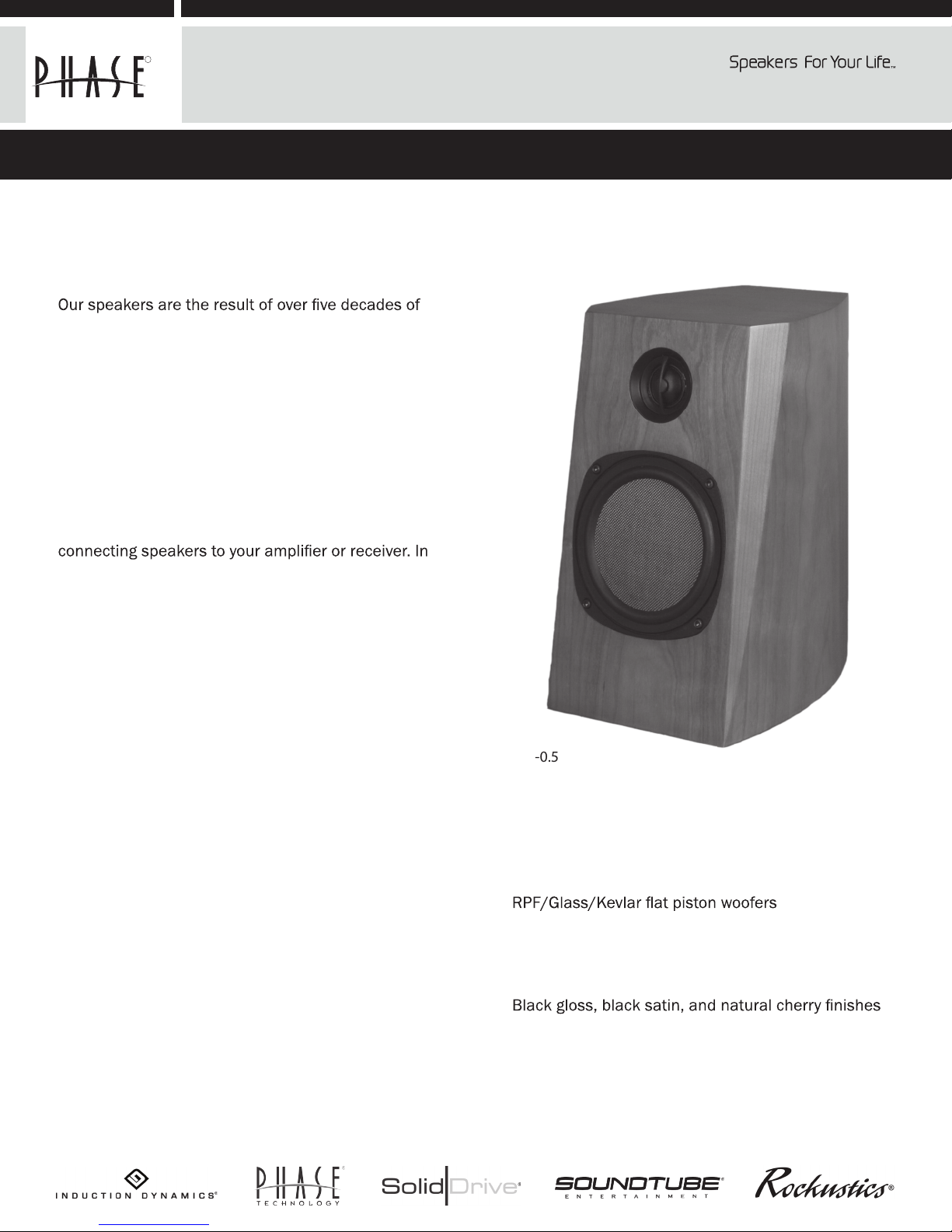
PC-0.5
PC SERIES FEATURES:
Handcrafted quality
2-Way, 3 -Way, and 4 -Way spea kers
So ft dome t weeter
Absolute Phase
Magnetic shielding
Key-hole style mounting brac ket
TM
C ross overs
Phase Technology Copporation www.phasetech.com
MSE Audio 8005 W. 110th St., Suite 208 Overland Park, KS 66210 855.663.5600 www.mseaudio.com
Page 2
SAFETY INSTRUCTIONS
CAUTION
RISK OF ELECTRIC
SHOCK
CAUTION: To reduce the risk of electric shock, do not remove cover (or
back). No user-serviceable parts inside. Refer servicing to qualied service
personnel.
Explanation of Graphical Symbols
The lightning ash with arrowhead symbol, within
an equilateral triangle, is intended to alert you to the
presence of un-insulated “dangerous voltage: within the
product’s enclosure that may be o sucient magnitude
to constitute a risk of electric shock to persons.
The exclamation point within an equilateral triangle
is intended to alert you to the presence of important
operating and maintenance (servicing) instructions in the
!
1. Read Instructions - All the safety and operating
instructions should be read before the appliance is
operated.
2. Retain Instructions - The safety and operating
instructions should be retained for future reference.
3. Heed Warnings - All warnings on the appliance and
in the operating instructions should be adhered to.
4. Follow Instructions - All operating and other
instructions should be followed.
5. Water and Moisture - The appliance should not
be used near water - for example, near a bathtub,
washbowl, kitchen sink, laundry tub, in a wet basement,
or near a swimming pool, etc.
6. Carts and Stands - The appliance should be used
only with a cart or stand that is recommended by the
manufacturer.
PORTABLE CART WARNING
literature accompanying the appliance.
!
from heat sources such as radiators, stoves, or other
appliances that produce heat.
10. Power Source - The appliance should be
connected to a power supply only of the type described
in the operating instructions or as marked on the
appliance.
11. Power Cord Protection - Power supply cords
should be routed so that they are not likely to be
walked on or pinched by items placed up or against
them, paying particular attention to cords at plugs,
convenience receptacles, and the point where they exit
from the appliance.
12. Cleaning - The appliance should be cleaned only
as recommended by the manufacturer.
13. Nonuse Periods - The power cord of the
appliance should be unplugged from the outlet when
left unused for a long period of time.
14. Object and Liquid Entry - Care should be taken
so that neither objects fall nor liquids spill into the inside
of the appliance.
15. Damage Requiring Service - The application
should be serviced by qualied service personnel when:
a. the power supply cord or the plug has been
damaged,
b. objects have fallen onto or liquid has been spilled
into the appliance,
c. the appliance has been exposed to rain,
d. the appliance does not appear to operate normally
or exhibits a marked change in performance, or
e. the appliance has been dropped or the cabinet
damaged.
16. Servicing - The user should not attempt to service
the appliance beyond those means described in the
operating instructions. All other servicing should be
referred to qualied service personnel.
17. Grounding or Polarization - Precautions should
be taken so that the grounding or polarization means of
an appliance is not defeated.
7. Wall or Ceiling Mounting - The appliance should be
mounted to a wall or ceiling only as recommended by
the manufacturer.
8. Ventilation - The appliance should be situated so
that its location or position does not interfere with its
proper ventilation. For example, the appliance should not
be situated on a bed, sofa, rug, or similar surface that
may block the ventilation openings; or placed in a builtin installation, such as a bookcase or cabinet that may
impede the ow of air through the ventilation openings.
9. Heat - The appliance should be situated away
APPLICABLE FOR USA, CANADA OR WHERE
APPROVED FOR USAGE
CAUTION: TO PREVENT ELECTRIC SHOCK, MATCH WIDE
BLADE PLUG TO WIDE SLOT, INSERT FULLY.
ATTENTION: POUR EVITER LES CHOCS ELECTRIQUES,
INTRODUIRE LA LAME LA PLUS LARGE DE LA FICHE
DANS LA BORNE CORRESPONDANTE DE LA PRESE ET
POUSSER JUSQU AU FOND.
Page 3

GETTING STARTED AND PRECAUTIONARY NOTES
For proper connection and therefore full enjoyment of your new Phase Technology speakers, we encourage you to
read this owners’ manual thoroughly, even if you are very familiar with installing speakers and home entertainment
equipment.
Speaker placement is very subjective. Placement follows the guidelines for the developers of multi-channel home
entertainment systems, yet is also guided by personal preferences. The proper spacing, location and adjustment
of front, rear and center-channel speakers as well as subwoofers are critical for complete enjoyment of your new
speakers. This manual covers these topics thoroughly.
Before connecting your new speakers or other system components, turn the system power off and unplug your
amplier to avoid any possibility of damage from power surges or unbalanced loads before the system is properly
connected.
Observe speaker polarity carefully! Every cable, speaker terminal and amplier connection are clearly marked to
show their positive (+) and negative (-) polarities. For ideal system performance, always connect the positive side of the
cable (marked with a stripe, color and /or other indicator) to the positive terminals on your speakers and amplier and
the negative side of the cable to the negative terminals.
Amplier selection is critical to your enjoyment of your new speakers. If you are considering upgrading your
current component amplier or multi-function receiver, we suggest purchasing as much power as your budget can
afford. It will always be preferable to have an affordable high-powered model with fewer “bells and whistles” than a
lower-powered model straining to operate near its power limits.
High volume settings that produce audible distortion – indicating an under-powered amplier – could eventually
damage your speakers and your amplier.
Begin and end listening sessions at low volume levels so you will not power up your system the next time with
possibly harmful high voltages. A damaging surge also could result if you change the input source (from FM tuner to CD
player, for example) at high volume levels.
If you suspect that one channel of your amplier has failed, have it repaired immediately by your dealer. Damage
to your speakers could occur if you switch between the good and defective channels.
TWO-CHANNEL (STEREO) SPEAKERS
Phase Technology audiophile speaker pairs for stereo applications can be affected by listening room geometry,
furnishings and xtures. Experimentation with placing your new speakers in your unique listening environment will
dictate how you arrive at the nal answer.
We recommend starting the positioning process by selecting a favorite recording to use as the reference source.
Place your new stereo speakers 1-3 feet away from rear and side walls and 6-8 feet apart. With bookshelf models, the
tweeters (small, high-frequency drivers) should be positioned at about ear level when you’re seated in your favorite
listening position.
In most rectangular rooms, the speakers will sound best when placed along the short wall; but again, experimentation
will provide the best answer. Move the speakers around slightly to determine any changes in sound balance and stereo
imaging. Even try angling the speakers slightly toward your listening area. You may be surprised by the differences you
will hear with even the slightest adjustments.
Owners of Phase Technology speakers equipped with the company’s acclaimed variable-axis soft dome tweeter have
additional latitude in speaker placement. Please see the Specications chart on page 8.
Page 4

HOME THEATER SYSTEMS SPEAKER PLACEMENT
Today’s digital multi-channel home theater technology has elevated the art of “surround sound” to reproduce the
movie theater experience in your own home. Speaker requirements and placement are vitally important in reproducing
these multi-media effects.
Two front speakers (left and right), two surround speakers (left and right), a center-channel speaker, and a subwoofer
dene the minimum arrangement for modern multi-channel systems. Placement of speakers in your room will impact
the nal listening experience. To position your speakers, there are some general guidelines that take room size, shape,
and xtures and furnishings into account. Use the following illustrations as a general guide for speaker placement in a
typical home theater system.
LF
LS RS
5.1 HOME THEATER SYSTEM
In a 5.1 home theater system, the center channel (C) should be
placed at 0º directly below or above the video screen, the left front
(LF) and right front (RF) speakers should be placed at 30º from the
listening area, and the left and right surrounds (LS and RS) should
be placed at 110º. All ve speakers should be placed at or near ear
level.
C
RF
SUB
LF
SUB
LS
LR RR
7.2 HOME THEATER SYSTEM
In a 7.2 home theater system, the center channel (C) should be
placed at 0º directly below or above the video screen, the left front
(LF) and right front (RF) speakers should be placed at 30º from the
listening area, and the left and right surrounds (LS and RS) should be
placed at 90º. The left rear (LR) and right rear (RR) speakers should
be placed at 150º. All seven speakers should be placed at or near
ear level.
C
RF
SUB
RS
Front speakers should be placed 6-8 feet apart (or on the sides or your screen if your screen is wider) to fully separate
the left and right channels. Whether placed on speaker stands or on shelves, your speakers should be at or slightly
above ear level.
Rear surround speakers also should be placed at or slightly above your listening position for the best reproduction of
surround-sound effects. Ideally, they should be facing into your favorite listening position from either side of the room
Center speaker placement should be, if possible, directly on top of or under your TV monitor or projection TV screen.
Center speakers should be placed in a horizontal orientation, directly below (or above) the center of your video
screen. This correctly positions the critical sound track information (usually dialogue) that lmmakers direct to the
center channel. Phase Technology center speakers are magnetically shielded so that they will not interfere with the
performance of a video monitor (TV). The two center channel speakers in the Premier Collection (PC-3.5 and PC-33.5)
both include a table-top stand for placement on tables or shelves.
Page 5

PC-SURROUND II PLACEMENT AND MOUNTING
The PC Surround rear-effects home-theater speaker offers you wide latitude of acoustic performance, system options
and speaker placement (including wall, shelf and stand mounting.) Using the toggle switch located adjacent to the
speaker terminals on the rear of the cabinet, the speaker can be changed from bipolar to dipolar mode to suit personal
listening preferences.
In bipolar mode, the PC Surround serves as a full range speaker system to meet the recommended technical
specications for rear surround speakers in a Dolby Digital and DTS 5.1-7.2 home theater systems. As a dipolar speaker,
it offers the diffused, subtle effect of out-of-phase drivers with a strong on-axis null polar pattern for more diffused
surround effects.
In order for this effect to work in proper phase with the other speakers in your home theater they need to be placed
in the proper orientation. Whether they are mounted on a stand, shelf or hung upside down on a wall the direction the
arrows point on the rear of the cabinets will help you orient the surround speakers properly. For 5.1 systems when
placed on a sidewall the arrows should point forward toward the front main speakers. When placed on a rear wall the
speakers should be oriented so the arrows point away from each other. For 7.1 systems the rear speakers should be
placed so the arrows are pointing toward each other . The side speakers remain as mentioned above.
The convenient “Key-hole” style mounting bracket on the rear of the speaker can be used for surface mounting with
the appropriate mounting anchor. Please be sure that the anchor has a #8 or #10 screw head on it to properly t the
hanger. Other types of standard speaker mounts may be used with the speakers as well. Please check with your Phase
Tech dealer for recommendations. Note: It is very important whichever method you use to be certain the mounting
screws or anchors will support the weight of the speaker. Self-stick rubber bumpers are provided with the PC Surround.
A bumper should be attached to each rear corner of the cabinet. These bumpers space the speaker away from the
wall to allow clearance for your speaker wires.
SPEAKER CONNECTIONS Please refer to the diagram on the following page for speaker connections.
The following instructions apply whether you are using a separate amplier or Home Theater receiver. For simplicity we
will use the term “amplier” throughout this manual to mean both. With system power off and your amplier unplugged,
please follow these steps:
Special Note: Observe Speaker Polarity Carefully!
Every cable, speaker and amplier is clearly marked to show their positive (+) and negative (-) terminals. Amps and
speakers may use some combination of these symbols and/or colors to indicate positive (usually red) and negative
(usually black or white) connections. One strand of your cable will also be ridged and/or marked with a colored line
or other indicator on the positive side. For proper polarity and, thus, ideal system performance, always connect the
positive side of the cable to the positive terminals on your speakers and amplier and the negative side of the cable
to the negative terminals.
Front Speakers: The pair of front speaker connections (left and right) on your amplier will be labeled “Front” or
“Main.” Connect the speaker cables for your left and right front speakers using these terminals and then connect the
cables to the front satellites. Observe positive and negative polarities.
Center Speaker: The center speaker connections on your amplier will be labeled “Center” or “Center Channel.”
Connect the speaker cables for your center channel speaker using these terminals and then connect the cables to the
center speaker. Observe positive and negative polarities.
Surround Speakers: The pair of surround connections (left and right) on your amplier will be labeled “Surround.”
Connect the speaker cables for your left and right surround speakers using these terminals and then connect the
cables to surround satellite speakers. Observe positive and negative polarities.
Rear Speakers (used in a 7.1 or 7.2 system): The pair of rear connections (left and right) on your amplier will
be labeled “Rear.” Connect the speaker cables for your left and right rear speakers using these terminals and then
connect the cables to the rear satellite speakers. Observe positive and negative polarities.
Page 6

Left
Front
Center Speaker
Right
Front
SUB OUT
Line Input
Right
Surround
Left
Surround
Right
Left
Front
Front
Amplier Panel
Center
Channel
Left
Surr.
Right
Surr.
SPECIAL PRODUCT FEATURES
Adjusting Variable-Axis, Soft-Dome Tweeters
Some Phase Technology speakers feature the company’s acclaimed variable-axis soft-dome tweeter (refer to
the model specications on page 8 of this manual) offering even greater latitude in selecting speaker locations and listening positions.
Subwoofer
This revolutionary tweeter can be adjusted by hand to direct the high frequencies towards a specic listening area for optimal tonal balance and channel separation. This enables owners of these Phase Technology
models to place the speakers where they look or t best and then aim the tweeter for best effect.
When adjusting these units, be careful to press on the outer rims only, avoiding contact with the center, or
soft dome, of the speaker. A series of adjustments may be necessary to achieve the ideal clarity and smoothness of the high frequencies that the variable-axis soft-dome tweeter was designed to present.
Bi-Wired Connections
Some Phase Technology premium audiophile speakers are equipped for be-wiring, with four speaker terminals instead of two. This may enhance speaker performance by using an additional pair of speaker cables.
In order to bi-wire these speakers, remove the gold-plated strips between the speaker terminals and connect two cables between your amplier’s positive output terminal and the two positive (red) terminals on the
speaker. Then connect the other two cables between the amp’s negative output terminal and the two negative (black) terminals on the speakers.
If you chose not to bi-wire your speakers, do not remove the metal strips between the speaker terminals.
Connect each cable in the standard manner, with one cable each between the positive and negative speaker
terminals and your amplier.
Page 7

Floor Spikes
Floor spikes may have been provided with your new Phase Technology speakers to steady the speaker cabinets, especially on carpeting and uneven oor surfaces. Because most speakers tend to rock back and forth
in small increments due to the force of the in/out motions of speaker drivers, these movements can affect
the speakers’ performance.
Attach the oor spikes by screwing them into the pre-drilled holes in the base of the speaker and tighten the
nuts securely. The sharp points will penetrate the carpet to make a more solid contract with the underlying
oor surface.
If your oor is not rigid, the spikes may actually add to the rocking motion, so we recommend you audition
the speakers with and without the spikes inserted to see if you discover a personal preference in the sound
quality.
Be especially careful when moving speaker cabinets with the spikes attached, as the points could damage
carpeting or scratch oors.
CARING FOR YOUR SPEAKERS
All Phase Technology speakers are nished with a high degree of craftsmanship in either hand polished paint or vinyl
laminates. We recommend using a lint-free rag with a small amount of glass cleaner to maintain the long-lasting beauty
of the nish. Avoid products containing silicones, oils, oil derivatives, or solvents. Enclosures nished in vinyl laminates
may be cleaned with a damp cloth as necessary.
MAINTENANCE AND SERVICE
Because of Phase Technology’s uncompromising quality control programs, it’s unlikely that your speakers will ever
need service if connected and used as outlined in this Owners’ Manual. In the unlikely event that a problem does occur,
please contact your Phase Technology dealer. Your dealer has the necessary factory-authorized parts and trained
technicians to quickly restore your speaker to its original performance specications.
WARRANTY
LIMITED WARRANTY
Phase Technology warrants its loudspeakers to be free from defects in material and workmanship for a period of ten
(10) years for speaker product and three (3) years for the electronic components to the original purchaser. Purchase
must be made from an authorized Phase Technology dealer.
This warranty does not cover service or parts to repair damage caused by misuse, abuse, damage while in transit,
alterations, unauthorized repairs, failure to follow instructions, re, ood or any other cause beyond the reasonable
control of Phase Technology. Defects in speaker cabinets or grilles must be brought to the attention of your dealer
immediately after purchase. This warranty will be void if the products’ serial number has been altered or removed.
To obtain warranty service, defective product must be shipped in its original carton or equivalent together with original
invoice or bill of sale, insured and prepaid to your authorized Phase Technology dealer or the factory when warranty
service is requested.
If you choose to return the defective product to the factory you must rst call us at (888) phase-tk to obtain a Return
Authorization number prior to shipping. Product repaired under this warranty will be returned to you freight collect.
Page 8

SPECIFICATIONS
Woofer
Midrange N/A N/A 1.5” woven, synthetic soft dome
Tweeter 1” woven, synthetic soft dome 1” woven, synthetic soft dome 1” woven, synthetic soft dome
Impedance 4 ohms 4 ohms 4 ohms
Frequency Response 58 Hz - 22 kHz 40 Hz - 22 kHz 32 Hz - 22 kHz
Sensitivity 88 dB 90 dB 91 dB
Recommended Amp 20 - 120 watts 20 - 150 watts 20 - 250 watts
Power
Dimensions* 6.9” W x 11.5” H x 9.6” D* 7.9” W x 13.6” H x 12.3” D* 14.75” W x 45.5” H x 9” D*
Finish Black Gloss or Natural Cherry Black Gloss or Natural Cherry Black Gloss or Natural Cherry
Optional Accessories SST-28 speaker stand SST-28 speaker stand N/A
*Add 1” to depth for connection.
PC-0.5
PC-1.5
PC-9.5
SPECIFICATIONS
Woofer
Midrange 1.5” woven, synthetic soft dome N/A (2) 4” polypropylene
Tweeter 1” woven, synthetic soft dome 1” woven, synthetic soft dome (2) 1” woven, synthetic soft dome
Impedance 4 ohms 4 ohms 4 ohms
Frequency Response 36 Hz - 22 kHz 56 Hz - 22 kHz 60 Hz - 22 kHz
Sensitivity 90 dB 90 dB 89 dB
Recommended Amp 20 - 250 watts 20 - 200 watts 20 - 150 watts
Power
Dimensions* 7.9” W x 22” H x 12.3” D* 6.9” W x 18” H x 9.6” D* 14.5” W x 15.25” H x 5.15” D*
Finish Black Gloss or Natural Cherry Black Gloss or Natural Cherry Black Gloss or White
Optional Accessories SST-28 speaker stand SST-28 speaker stand SST-28 speaker stand
*Add 1” to depth for connection.
PC-3.5
PC-33.5
PC-Surr II
Phase Technology Copporation www.phasetech.com
MSE Audio 8005 W. 110th St., Suite 208 Overland Park, KS 66210 855.663.5600 www.mseaudio.com
 Loading...