

Page 1

[P350]
OWNER’S MANUAL & INSTALL GUIDE
Page 2
TE CH NO LO GY
R
[P350]
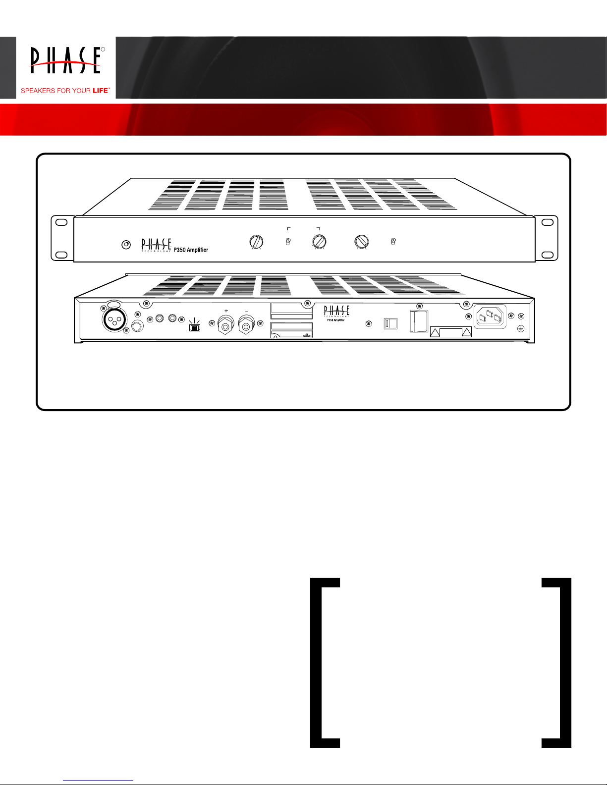
Owners Manual / Installation Instructions
CLASS-G HIGH CURRENT MONO BLACK AMPLIFIER
BASS EQ
POWER
PUSH
INPUT
12V TRIGGER
IN OUT
UNBALANCEDBALANCED
ON
TRIGGER
MODE
MUSIC
12V
-3 dB +6 dB
OUTPUT
4-16 OHMS
IN
OUT
[FEATURES] • SOFT CLIPPING (SUBWOOFER MODE) • SHORT CIRCUIT / OVERLOAD • THERMOSTATIC VARIABLE
SPEED FAN COOLING • THERMAL OVERLOAD PROTECTION • TRANSFORMER THERMAL PROTECTION
• OVER-CURRENT PROTECTION
Thank you for choosing Phase Technology® speakers. We
know there are a wide variety of choices available today, and
we sincerely appreciate your purchase of our product. Phase
Technology speakers are built to exacting standards and will
provide many years of listening enjoyment.
The P350 is the companion amplier to Phase Technology
custom in-wall subwoofer systems but its use is not limited
to only subwoofer applications. It also has the exibility of
operation as a full range high current, high performance,
mono-block audio power amplier.
SUB FILTER LEVEL PHASE
CROSSOVER
40
LFE 120HZ
MINM AX
INPUT
VOLTAGE
180
0
115V
POWER
ON OFF
115V 60 Hz/ 230V 50 Hz
AC INPUT 600W MAX
a problem with set-up or operation, please contact one of our
authorized dealers for assistance, or contact us directly.
Phase Technology® Corporation
8005 W. 110th St., Suite 208
Overland Park, KS 66210
855.663.5600 (Domestic)
+1.913.663.5600 (International)
Fax: 913.663.3200
Our speakers are the result of over ve decades of designing
and manufacturing. We hold many key patents in loudspeaker
technology including the soft-dome tweeter. Our mission, our
passion is to constantly advance the art and science of accurate
audio reproduction. Our dedication insures your new speakers
will accurately reproduce all the impact, detail and delicacy of
today’s digital technology.
Regardless of application, serious audiophile listening or home
theater, we recommend that you take the time to read this
manual thoroughly before connecting speakers to your amplier
or receiver. In the highly unlikely event that you should experience
SAFETY INSTRUCTIONS 3
GETTING STARTED AND PRECAUTIONARY NOTES 3
SUBWOOFER PLACEMENT 4
SPEAKER CONNECTIONS 4
OPERATING INSTRUCTIONS & CONTROLS 4
RACK MOUNTING 5
CARING FOR YOUR SPEAKERS 5
MAINTENANCE AND SERVICE 5
TROUBLESHOOTING 5
WARRANTY 5
SPECIFICATIONS 5
2
Page 3

[SAFETY INSTRUCTIONS]
RISK OF ELECTRIC SHOCK
CAUTION
DO NOT OPEN
8. Ventilation - The appliance should be situated so that its location or position
does not interfere with its proper ventilation. For example, the appliance should not
be situated on a bed, sofa, rug, or similar surface that may block the ventilation
openings; or placed in a built-in installation, such as a bookcase or cabinet that
may impede the ow of air through the ventilation openings.
9. Heat - The appliance should be situated away from heat sources such as
radiators, stoves, or other appliances that produce heat.
CAUTION: To reduce the risk of electric shock, do not remove cover (or back).
No user-serviceable parts inside. Refer servicing to qualied service personnel.
Explanation of Graphical Symbols
The lightning ash with arrowhead symbol, within an
equilateral triangle, is intended to alert you to the presence
of un-insulated “dangerous voltage: within the product’s
enclosure that may be off sufcient magnitude to constitute
a risk of electric shock to persons.
The exclamation point within an equilateral triangle is
intended to alert you to the presence of important operating
and maintenance (servicing) instructions in the literature
accompanying the appliance.
1. Read Instructions - All the safety and operating instructions should be read
before the appliance is operated.
2. Retain Instructions - The safety and operating instructions should be retained
for future reference.
3. Heed Warnings - All warnings on the appliance and in the operating instructions
should be adhered to.
4. Follow Instructions - All operating and other instructions should be followed.
5. Water and Moisture - The appliance should not be used near water - for
example, near a bathtub, washbowl, kitchen sink, laundry tub, in a wet basement,
or near a swimming pool, etc.
6. Carts and Stands - The appliance should be used only with a cart or stand that
is recommended by the manufacturer.
PORTABLE CART WARNING
10. Power Source - The appliance should be connected to a power supply only
of the type described in the operating instructions or as marked on the appliance.
11. Power Cord Protection - Power supply cords should be routed so that they
are not likely to be walked on or pinched by items placed up or against them,
paying particular attention to cords at plugs, convenience receptacles, and the
point where they exit from the appliance.
12. Cleaning - The appliance should be cleaned only as recommended by the
manufacturer.
13. Nonuse Periods - The power cord of the appliance should be unplugged from
the outlet when left unused for a long period of time.
14. Object and Liquid Entry - Care should be taken so that neither objects fall
nor liquids spill into the inside of the appliance.
15. Damage Requiring Service - The application should be serviced by qualied
service personnel when:
a. the power supply cord or the plug has been damaged,
b. objects have fallen onto or liquid has been spilled into the appliance,
c. the appliance has been exposed to rain,
d. the appliance does not appear to operate normally or exhibits a marked change
in performance, or
e. the appliance has been dropped or the cabinet damaged.
16. Servicing - The user should not attempt to service the appliance beyond
those means described in the operating instructions. All other servicing should be
referred to qualied service personnel.
17. Grounding or Polarization - Precautions should be taken so that the
grounding or polarization means of an appliance is not defeated.
APPLICABLE FOR USA, CANADA OR WHERE APPROVED FOR USAGE
7. Wall or Ceiling Mounting - The appliance should be mounted to a wall or
ceiling only as recommended by the manufacturer.
[GETTING STARTED AND PRECAUTIONARY NOTES]
For proper connection and therefore full enjoyment of your new Phase Technology speakers, we encourage you to read this owners’ manual thoroughly, even if you are
very familiar with installing speakers and home entertainment equipment. Speaker placement is very subjective. Placement follows the guidelines for the developers of
multi-channel home entertainment systems, yet is also guided by personal preferences. The proper spacing, location and adjustment of front, rear and center-channel
speakers as well as subwoofers are critical for complete enjoyment of your new speakers. This manual covers these topics thoroughly.
Before connecting your new speakers or other system components, turn the system power off and unplug your amplier to avoid any possibility of damage from power
surges or unbalanced loads before the system is properly connected. Observe speaker polarity carefully! Every cable, speaker terminal and amplier connection are clearly
marked to show their positive (+) and negative (-) polarities. For ideal system performance, always connect the positive side of the cable (marked with a stripe, color and
/or other indicator) to the positive terminals on your speakers and amplier and the negative side of the cable to the negative terminals.
Amplier selection is critical to your enjoyment of your new speakers. If you are considering upgrading your current component amplier or multi-function receiver, we
suggest purchasing as much power as your budget can afford. It will always be preferable to have an affordable high-powered model with fewer “bells and whistles” than
a lower-powered model straining to operate near its power limits. High volume settings that produce audible distortion – indicating an under-powered amplier – could
eventually damage your speakers and your amplier.
Begin and end listening sessions at low volume levels so you will not power up your system the next time with possibly harmful high voltages. A damaging surge also could
result if you change the input source (from FM tuner to CD player, for example) at high volume levels. If you suspect that one channel of your amplier has failed, have it
repaired immediately by your dealer. Damage to your speakers could occur if you switch between the good and defective channels.
CAUTION: TO PREVENT ELECTRIC SHOCK, MATCH WIDE BLADE PLUG TO WIDE SLOT,
INSERT FULLY.
ATTENTION: POUR EVITER LES CHOCS ELECTRIQUES, INTRODUIRE LA LAME LA PLUS
LARGE DE LA FICHE DANS LA BORNE CORRESPONDANTE DE LA PRESE ET POUSSER
JUSQU AU FOND.
3
Page 4

[SUBWOOFER PLACEMENT]
Subwoofer placement is less critical, because the frequencies they reproduce are omni directional. This means the human ear doesn’t perceive these low frequencies as
coming from a specic direction, enabling placement of a subwoofer virtually anywhere in the listening room.
It’s best, however, to keep a subwoofer within the sound eld of the other speakers. The closer the subwoofer is to a wall, the louder and more intense its bass output
will be: this effect is even stronger when the sub is placed in or near a room’s corner. If using two subwoofers, start by placing them next to the front left and right
speakers, in both front corners or one in the corner and one 1/3 of the way along the front wall from the corner. Each room is different. Experiment with these options or
try other locations until you get the best results. If you must choose a less-than-ideal position, the output level of Phase Technology powered subwoofers is adjustable
to compensate for your listening environment.
[SPEAKER CONNECTIONS]
The following instructions apply whether you are using a separate amplier or Home Theater receiver. For simplicity we will use the term “amplier” throughout this manual
to mean both.
SPECIAL NOTE: TURN OFF AND UNPLUG YOUR AMPLIFIER BEFORE CONNECTING SPEAKERS.
SPECIAL NOTE: OBSERVE SPEAKER POLARITY CAREFULLY!
Every cable, speaker and amplifier is clearly marked to show their positive (+) and negative (-) terminals. Amps and speakers may use some combination of
these symbols and/or colors to indicate positive (usually red) and negative (usually black or white) connections. One strand of your cable will also be ridged and/
or marked with a colored line or other indicator on the positive side. For proper polarity and, thus, ideal system performance, always connect the positive side
of the cable to the positive terminals on your speakers and amplifier and the negative side of the cable to the negative terminals.
[OPERATING INSTRUCTIONS AND CONTROLS] FRONT PANEL
SUB FILTER LEVEL PHASE
CROSSOVER
IN
40
OUT
LFE 120HZ
MINM AX
180
0
POWER
BASS EQ
-3 dB+ 6 dB
1. POWER: The power LED on the front panel indicates the P350 status. A red indicator light means the main power is on and the P350 is in the standby mode. A green
indicator LED means that the P350 is active and should be reproducing an audio signal. An orange or ashing red to orange LED means that the P350 has a problem or is
overheated. Please check to be sure that your speaker is hooked up properly and is not shorted and there is adequate ventilation around the P350.
2. BASS EQ: The bass equalizer control allows the adjustment of bass equalization around 30Hz to compensate for subwoofer placement. The adjustment range is from -3
dB to +6 dB. This control is active in both the Subwoofer and LFE modes.
3. SUB FILTER, IN/OUT SWITCH: The mode selector switch selects the operating mode of the amplier for either a full range audio mono-block amplier (OUT) or mono
subwoofer amplier (IN). In the OUT full range position the BASS EQ, CROSSOVER, LFE, PHASE and Soft Limit circuits do not function.
4. CROSSOVER/LFE: The Low Pass crossover control is adjustable from 40-120 Hz. This control should be adjusted to obtain the smoothest transition in sound between
the subwoofer and your main speaker system when other electronic crossovers are not being used such as a home theater receiver or processor. When using the P350
amplier with a home theater receiver or processor set the switch to the LFE position. This will allow you to properly crossover the subwoofer with your other speakers
using the receiver or processor. Please check the owner’s manual of your receiver or processor for the proper setting.
5. LEVEL: This control is used for level matching of the subwoofer system to the main loudspeakers. We recommend that you start with this control in about the 9-10
o’clock position as an initial setting and then adjust as necessary to match your other speakers. Use the level controls on the main equipment for ne adjustment of the
overall speaker levels.
6. PHASE: This switch is for adjusting the P350 amplier output phase to match that of the main speakers. In the 0° setting the amplier signal input and output are in
phase. In the 180° setting the output signal of the amplier is inverted or out of phase with the main speakers. Please experiment with this setting. The correct setting is that
which yields the fullest bass and smoothest blend of the subwoofer with your main speakers. This control is active in both the Subwoofer and LFE switch setting positions.
[OPERATING INSTRUCTIONS AND CONTROLS] BACK PANEL
PUSH
INPUT
UNBALANCEDBALANCED
12V TRIGGER
IN OUT
ON
TRIGGER
MODE
MUSIC
OUTPUT
12V
4-16 OHMS
INPUT
VOLTAGE
7
POWER
ON OFF
115V
8
115V 60 Hz/ 230V 50 Hz
AC INPUT 600W MAX
9
1. BALANCED INPUT: This connector is for a balanced audio line level input and accepts standard XLR type connectors.
2. UNBALANCED INPUT: This connector accepts a standard RCA audio interconnect cables.
3. 12 V TRIGGER: The IN connector accepts a standard mini style phone plug and is used to remotely turn the P350 from standby to on. Connect one end to the P350 in
and the other to your receiver or processor trigger out. The OUT connector on the P350 acts as a remote trigger to turn additional equipment on and off.
4. TRIGGER MODE: The selector switch allows you to choose the standby mode of operation for the amplier. The ON position means that the P350 is constantly on and
will not revert to the standby mode. Use this mode if you are turning the power on and off from another source such as a switched outlet. The MUSIC position will wake up
the amplier when there is an audio signal present at the input connectors.The P350 will return to the standby mode in about 10 minutes after the input signal ceases. The
12V mode is for use in conjunction with remote 12 volt trigger features on your main receiver or processor.
5. OUTPUT: The speaker output connection terminals are 5-way binding posts. They accept banana plugs, pins or bare wires on your speaker cables. We recommend that
you use at least 14-gauge speaker wire for these hookup connections. The black terminal is the speaker negative (-) connection and the red terminal is the speaker positive
(+) connection. The speaker output of the P350 is compatible with standard 4-8 ohm speakers.
6. EXHAUST VENT: This is the exhaust opening for the internal cooling fan. It is very important that this opening and the ventilation holes on the top and bottom of the P350
are not blocked. Please allow adequate space around the amplier for ventilation.
7. INPUT VOLTAGE: The A/C power line voltage selector is used for properly matching the line voltage of your wall outlet to the P350 amplier. For the USA and Canada
this switch is set to the 110-120V position. For other countries check with your retailer for the proper setting and line cord requirements.
8. POWER ON/OFF: This is the master ON/OFF power control switch for the P350 amplier.
9. 3-PIN POWER CONNECTOR: The power line cord socket is for the connection of the main power cord from your wall outlet to the amplier. In the USA and Canada the
amplier is supplied with a standard IEC polarized power cord. For other countries you should check with your retailer for the proper line cord requirements.
4
Page 5

[RACK MOUNTING]
The P350 is supplied with rack mounting adapters for the convenience of installing the amplier in standard 19” equipment racks. The P350 occupies one (1) standard
rack unit position. The supplied adapters are easily attached to the left and right side of the P350 chassis with the supplied screws. Depending on the application it may
be necessary to remove the rubber isolation feet.
[CARING FOR YOUR PHASE TECHNOLOGY SPEAKER]
All Phase Technology speakers are nished with a high degree of craftsmanship in either hand polished paint or vinyl laminates. We recommend using a lint-free rag with
a small amount of glass cleaner to maintain the long-lasting beauty of the nish. Avoid products containing silicones, oils, oil derivatives, or solvents. Enclosures nished
in vinyl laminates may be cleaned with a damp cloth as necessary.
[MAINTENANCE AND SERVICE]
Because of Phase Technology’s uncompromising quality control programs, it’s unlikely that your speakers will ever need service if connected and used as outlined in this
Owners’ Manual. In the unlikely event that a problem does occur, please contact your Phase Technology dealer. Your dealer has the necessary factory-authorized parts
and trained technicians to quickly restore your speaker to its original performance specications.
[TROUBLESHOOTING]
NO SOUND
1. Verify that all components are plugged in and turned on.
2. Check all speaker wires and cables for loose connections.
3. Check to see if you have selected the proper source on your amplier.
VOICES DO NOT APPEAR TO COME FROM BETWEEN THE SPEAKERS / BASS RESPONSE IS WEAK
1. Verify that all speaker connections from the amplier to the speakers are running PLUS+ to PLUS+ and MINUS- to MINUS-.
2. Check to see if there are any furnishings or plants that may be blocking the output of a speaker.
SOUND, BUT NO BASS (MOST LIKELY IN SYSTEMS WITH A SUBWOOFER)
1. Verify that the subwoofer is plugged into an AC outlet and power is turned on.
2. Check that the speaker wire / cable going from the amplier/receiver to the subwoofer is securely fastened.
3. Check the volume control of the subwoofer.
4. Refer to your amplier/receiver manual to make sure you have adjusted its bass output properly.
MUDDY OR BOOMY BASS
1. Check the volume control for the subwoofer. Excess volume can cause speakers to sound distorted and unnatural.
2. Try adjusting the crossover control on the subwoofer or the subwoofer setup on your receiver to a slightly lower frequency (example:
reduce from 120 Hz to 80 or 60 Hz).
3. If the subwoofer or full size speaker is close to a corner, side or back wall, try moving it away from the wall. This may reduce the
“boomy” bass considerably.
4. Bookshelf speakers placed in a semi-enclosed space or cabinet can articially emphasize bass output. Reduce the bass control on
your amplier or move the speakers to the front of the cabinet. Alternatively, reposition the speakers to a more open location.
DISTORTED SOUND FROM THE SPEAKERS
1. This problem is usually caused by setting the volume control too high. Reduce the amplier/receiver volume to a lower level.
2. If noise and distortion are audible at higher volume levels, your amplier may not be powerful enough. Consider upgrading to a unit
with higher power.
NOTE: Remember, even though your Phase Technology speakers can handle considerable power levels, ANY speaker if used improperly can be damaged. Consult your Phase Technology dealer
for assistance in choosing a new amplier or receiver.
[WARRANTY]
LIMITED WARRANTY: Phase Technology warrants its
loudspeakers to be free from defects in material and
workmanship for a period of ten (10) years for speaker
product, limited lifetime for CI speakers, and three (3)
years for the electronic components to the original
purchaser. Purchase must be made from an authorized
Phase Technology dealer.
This warranty does not cover service or parts to repair
damage caused by misuse, abuse, damage while in
transit, alterations, unauthorized repairs, failure to follow
instructions, re, ood or any other cause beyond the
reasonable control of Phase Technology. Defects in
speaker cabinets or grilles must be brought to the attention
of your dealer immediately after purchase. This warranty
will be void if the products’ serial number has been altered
or removed.
Should your Phase Technology product require service,
please call the MSE Audio customer service department
for a return authorization. All merchandise returned to
Phase Technology without prior authorization will be
refused. For your return authorization number, please call
855.663.5600 or email sales@mseaudio.com.
Copyright © 2015 MS Electronics, LLC. All rights reserved. MSE Audio, Phase Technology and PhaseTech are registered trademarks and
“Speakers for your Life” is a trademark of MSE Audio, Overland Park, Kansas USA. Phase Technology is part of MSE Audio®. www.phasetech.com.
[SPECIFICATIONS]
MODES
AMPLIFIER POWER
CROSSOVER FREQUENCY
LFE FREQ RESPONSE
FULL-RANGE RESPONSE
LOW FREQUENCY EQ
INPUTS
INPUT SENSITIVITY
DAMPING FACTOR
INPUT IMPEDANCE
CURRENT CONSUMPTION 120V
DIMENSIONS (OVERALL)
WEIGHT
P350 CLASS-G HIGH CURRENT MONO BLOCK AMPLIFIER
Sub, LFE, Wide-Range
350 Watts RMS >.5% THD @ 4 Ohms, 700 Watts peak
225 Watts RMS >.5% THD @ 8 Ohms, 400 Watts peak
Low Pass 40 - 120 Hz; 24 dB/octave
20 - 500 Hz
10 Hz - 20 kHz +0/-.25 dB; 5 - 60 kHz +0/-3 dB
-3 dB to +6 dB @ 30 Hz
Gold-Plated Balanced RCA; Balance XLR
175 mV For Full Output Unbalanced/ 220 mV Balanced
<200
22K Unbalanced, 37.5K Balanced
3 Amps @ 8Ω; 5.5 Amps @ 4Ω Continuous
2” H x 17.25” W x 13.25” D
17 lbs.
5
Page 6

8
 Loading...