

Phase Technology CI-6.0 VIII QM, CI-6.1 VIII QM, CI-7.2 VIII QM, CI-7.3 VIII QM, CI-FGR Install Instructions Manual
...Page 1
T E C H N O L O G Y
Install instructions for CI round flush mount models:
CI-6.0 VIII QM CI-6.1 VIII QM CI-6.2s VIII QM CI-7.2 VIII QM CI-7.3 VIII QM
Thank you for purchasing Phase Technology CI custom installation
speakers. This eighth generation of high performance ceiling
mounted speakers features the same superb sonic performance as
our acclaimed PC Series cabinet speakers in addition to great
flexibility and easy installation. The most striking change to the series
VIII QM is a new look with the off-axis tweeter design. This feature
maximizes the speaker’s clarity and imaging by creating an
asymmetrical loading or diffraction patter, reducing the amount of
diffraction normally caused by a flange-to-ceiling junction.
The net result is the best sonic realism you can buy in an in-ceiling
speaker. All CI series speakers include self-resetting solid-state PTC
protection circuits. This unique system is able to detect when the
speaker is being over-driven and lowers the speaker volume until the
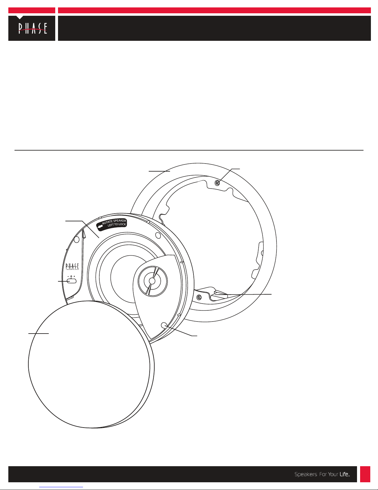
Universal flange & grille
assembly (CI-FGR QM)
(purchase separately)
Speaker/baffle
assembly
problem is corrected. Other features include liquid-cooled tweeters
for greater power handling, moisture-resistant materials in all of the
critical speaker components, galvanized steel speaker grilles and
stainless steel hardware for improved corrosion resistance.
The CI VIII QM in-ceiling series incorporates a new patent-pending
CI-FGR QM Quick Mount mounting system. No longer will
you have to suffer through holding the speaker in place overhead
while tightening the screws. The breakthrough comes from a newly
developed system of clamps that engage to hold the speaker in the
flange while you safely tighten
the clamps with a screwdriver. The
new Quick Mount system makes installation of the CI VIII QMs the
easiest you’ve ever done.
Flange clamp
screw (4x)
Tweeter adjustment
Grille
Flange clamp (4x)
The CI-FGR QM will clamp
material up to 1
Baffle clamp screw (4x)
1
/2” thick.
Choose the appropriate mounting location for each speaker.
When deciding upon a location, consider the following:
• Be certain your speaker wires can be run to or are accessible from these
locations.
• Make certain the wall or ceiling material is sturdy enough to support the
weight and vibration of the speakers.
• It is recommended that our pre-construction rough-in brackets (part
number RB-17*) be used whenever possible in new construction.
• Be certain the area behind the speaker is free of obstacles such as wall
studs, electrical wiring, pipes, etc.
• Each speaker should be positioned properly, relative to the listening area
for good coverage.
• Audio performance and room-to-room isolation will be improved if there is
some fiberglass insulation placed loosely behing the speaker.
*The RB-17 rough-in bracket is available for installations in new construction.
218-1240
Page 2
Install instructions for CI round flush mount models, Page 2
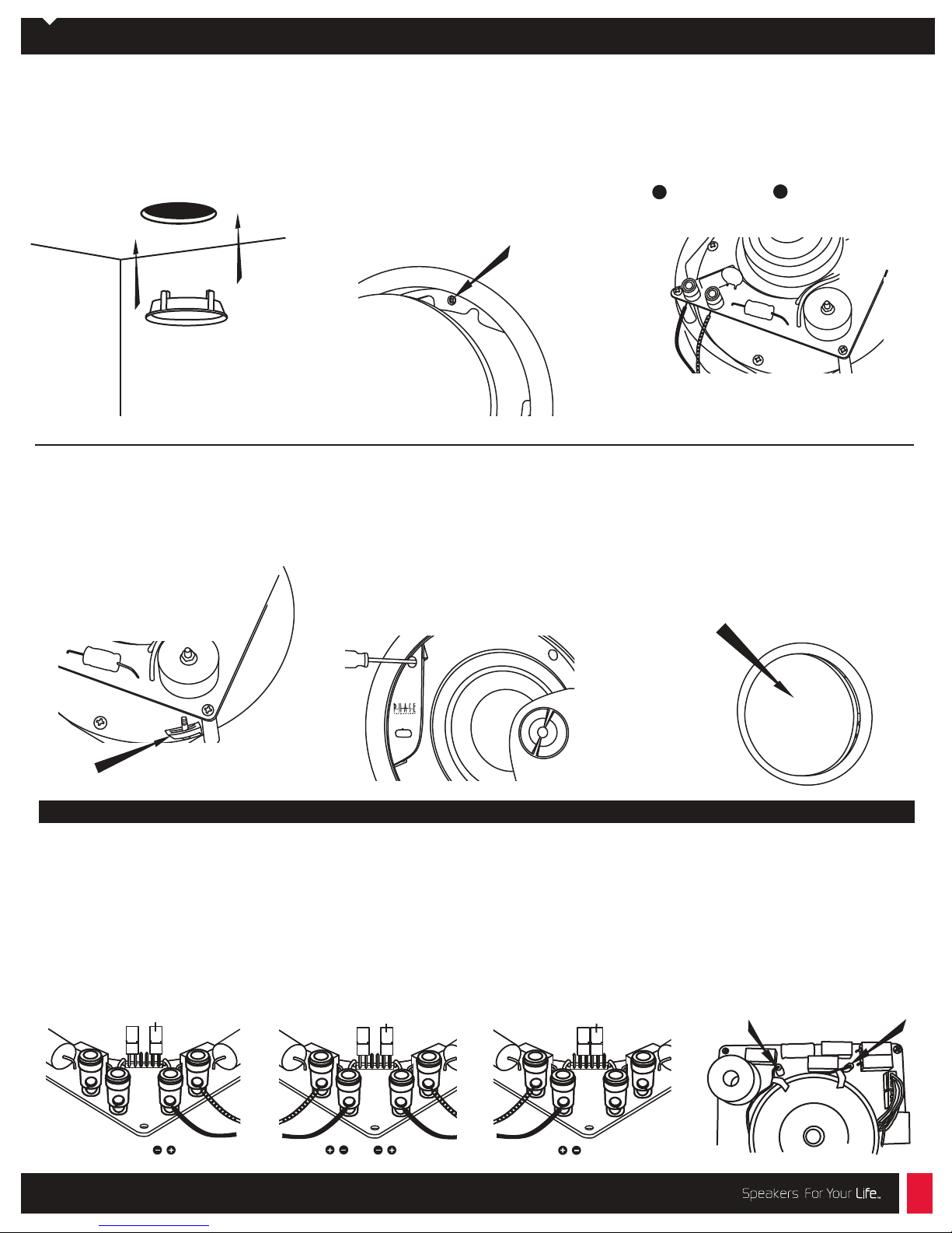
Flange Installation:
1. Using the supplied cutout template,
carefully mark the area to be cut out. Using
a drywall knife or saw, cut a hole in the
drywall and prepare the speaker wires for
connection to the speaker terminals.
4. Carefully place the speaker in the flange.
While exerting upward pressure, rotate the
speaker until it fits snugly and the speaker
surface is even with or slightly recessed
into the surface of the flange. Rotate the
speaker counter-clockwise (left) to secure
it in place. This will engage the Quick Mount
clamps on the back of the flange. Finish by
tightening the four clamp screws on the
speaker. CAUTION: Do not over-tighten.
2. Remove the grille from the mounting
flange by pressing it from behind. Insert the
mounting flange into the hole. Loosen the
flange clamping screws one turn (counter
clockwise) to release the clamp. Next,
tighten all four flange clamp screws evenly
to secure the flange to the wall. It is best to
tighten each screw with the same amount of
force (torque). CAUTION: Do not over-tighten.
NOTE: Special instructions for non-QM
Flanges
If you are installing a CI round speaker with
the QM clamps in a CI-FGR (non-QM flange)
remove the QM clamp feet by unscrewing
them from the speaker baffle. Insert the
speaker baffle into the flange and reuse the
screws from the clamp feet to attach the
speaker to the flange.
Speaker Installation:
3. Connect the speaker wires to the
spring-loaded input terminals on the rear of
the speaker, making sure no loose strands
are exposed. If connecting the CI-6.2s VIII QM,
see wiring options below.
+
Red/positive Black/negative
5. Using some familiar source material,
listen to the tweeter’s balance with the level
control in each of its three positions to find
your favorite.
6. Carefully replace the grille by pressing it
into the gap between the flange and the
baffle. Enjoy your new Phase Technology
speakers!
Grille
_
Quick Mount Clamp
Wiring options for the CI-6.2s
Stereo
FIG. 1 – 8 ohms: Use this
configuration to drive one channel
(left or right) of a stereo pair. Set
jumper plugs in the stereo position.
Connect the right or left signal wire to
the right set of terminals on the rear of
the speaker.
Jumper Plugs
stereo position
Stereo Point Source
Use this configuration to combine left
and right channels for full fidelity sound
from a single loud-speaker stereo source.
Set jumper plugs in the stereo position.
Connect right and left signal wires to the
spring-loaded terminals on the rear of
the speaker.
Jumper Plugs
stereo position
Left Channel
FIG.2 – 8 ohms:
Right ChannelRight Channel
Mono/S tereo
this configuration to drive one channel
(left or right ) of a stereo pair with a 4
ohm speaker load. Set jumper plugs in
the mono position. Connect the right or
left signal wire to the left set of posts
on the rear of the speaker. Acoustic
output of the speaker is increased by
3 dB in the configuration.
3.GIF2.GIF1.GIF
mono position (Bi-pole/di-pole)
Left Channel
FIG.3 – 4 ohms: Use
Jumper Plugs
6400 Youngerman Circle / Jacksonville, FL 32244 / (888)PHASE TK / www.phasetech.com
Bi-pole/Di -pole
configuration for home theater
applications. For bi-pole mode, connect
as in the Mono/ Stereo
one speaker to each surround channel.
For di-pole mode, connect speaker
inputs the same as Mono/ Stereo
instructions
connections of the marked tweeter wires
to put one of the tweeters out of phase.
FIG.4
FIG.4 – 4 ohms: Use this
surround
instructions (FIG.3):
(FIG.3), but reverse the + and –
 Loading...