

Page 1

CI-SERIES IN-CEILING
INSTALLATION INSTRUCTIONS
CI-6.0,6.1, 6.2S, 7.3
Thank you for your purchase of the Phase Technology custom installation speaker systems.
Phase Technology high performance in-ceiling products feature not only greater flexibility and ease of
installation, but also, the same sonic performance of our highly regarded Phase Technology free standing
speaker line.
Features of the new CI-Series speakers include self-resetting, solid state PTC circuit breakers on all CI speakers.
These unique devices detect when the speaker is being over-driven and lower the speaker volume until the
problem is corrected. The PTC device then resets itself for normal operation. The PTC device can be cycled
thousands of times without wearing out because there are no moving parts. The CI-Series speakers all have
liquid cooled tweeters for greater power handling, moisture resistant materials in all the critical speaker
components, galvanized steel speaker grilles for improved corrosion resistance and new performance
improvements for even greater realism.
MOUNTING INSTRUCTIONS
1. To install the CI baffle assembly, it is first necessary to install the CI-FGR universal flange and grille
assembly in the ceiling. The CI-FGR should be painted prior to installation of the CI baffle assembly.
2. Remove the grille from the CI-FGR by carefully prying up its edges with a small screwdriver or similar
tool.
3. Locate the speaker wire and attach it to the CI input terminals: red/plus, black/minus. See instructions for
wiring options on the CI-6.2S.
4. Carefully place the CI unit in the CI flange assembly making certain that the four V-shaped index marks on
the outer radius of the baffle and the inside radius of the flange line up.
5. Attach the CI unit to the CI flange with the four pre-installed 1” mounting screws on the baffle.
Phillips extension bit may be required for use with electric screw guns.
6. Adjust the tweeter level switch for the desired tweeter brightness and aim the pivoting 1” tweeter assem bly
toward the main listening position by pushing gently on the inside of the tweeter housing to rotate the
tweeter in the desired direction (CI-6.1 and CI-7.3).
7. Carefully line up the grille with the groove on the CI assembled unit and push into place. The grille should
mount almost flush with the flange.
8. If disassembly is required at a later date, the grille should be carefully pulled out around its edges with a
small screwdriver or similar tool. The CI unit may be removed by turning the four clamping screws counterclockwise 1 or 2 turns to release the clamping feet from the wall.
218-1224
A 2”-3” #2
Page 2
,
,
,
,
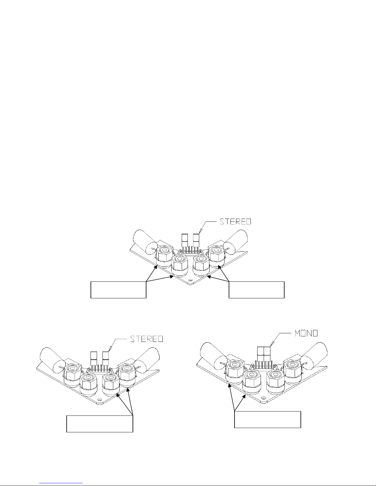
CI-6.2S WIRING OPTIONS
The CI-6.2S is a 2-way stereo speaker system in one housing incorporating a dual voice coil 6 ½” woofer, 2
dome tweeters and a stereo crossover assembly. This unique feature allows it to add a great degree of flexibility
to custom installations by simple alterations in the hook-up wiring. Please select the appropriate hook-up listed
below:
♦ Normal Stereo (Figure 1) hook-up provides summed left and right inputs at 8 ohms each that are combined
to yield a full range monaural output. This is the most popular configuration with the jumper plugs set in the
stereo position. It makes allowances for full fidelity sound to be delivered from a stereo source to a single
loudspeaker without the loss of any signal information. The rest of the hook-up configurations are normally
utilized when the CI-6.2S is being used in stereo pairs and provides impedance options that allow you the
best match with the rest of your installation.
♦ Full range 8 ohm single channel input (Figure 2), jumpers in stereo position when CI-6.2 used in stereo
pairs.
♦ Full range 4 ohm single channel input (Figure 3), jumpers in mono position when CI-6.2 used in stereo
pairs.
Figure 1
LEFT OR RIGHT
CHANNEL INPUT +
INPUT -
+
LEFT CHANNEL
INPUT +
-
RIGHT CHANNEL
Figure 2 Figure 3
LEFT OR RIGHT
-
CHANNEL INPUTS +
-
 Loading...