

Page 1
Install instructions for CI round flush mount models:
T E C H N O L O G Y
Thank you for purchasing Phase Technology Custom Installation
speakers. Before installing, please read through this installation
manual thoroughly.
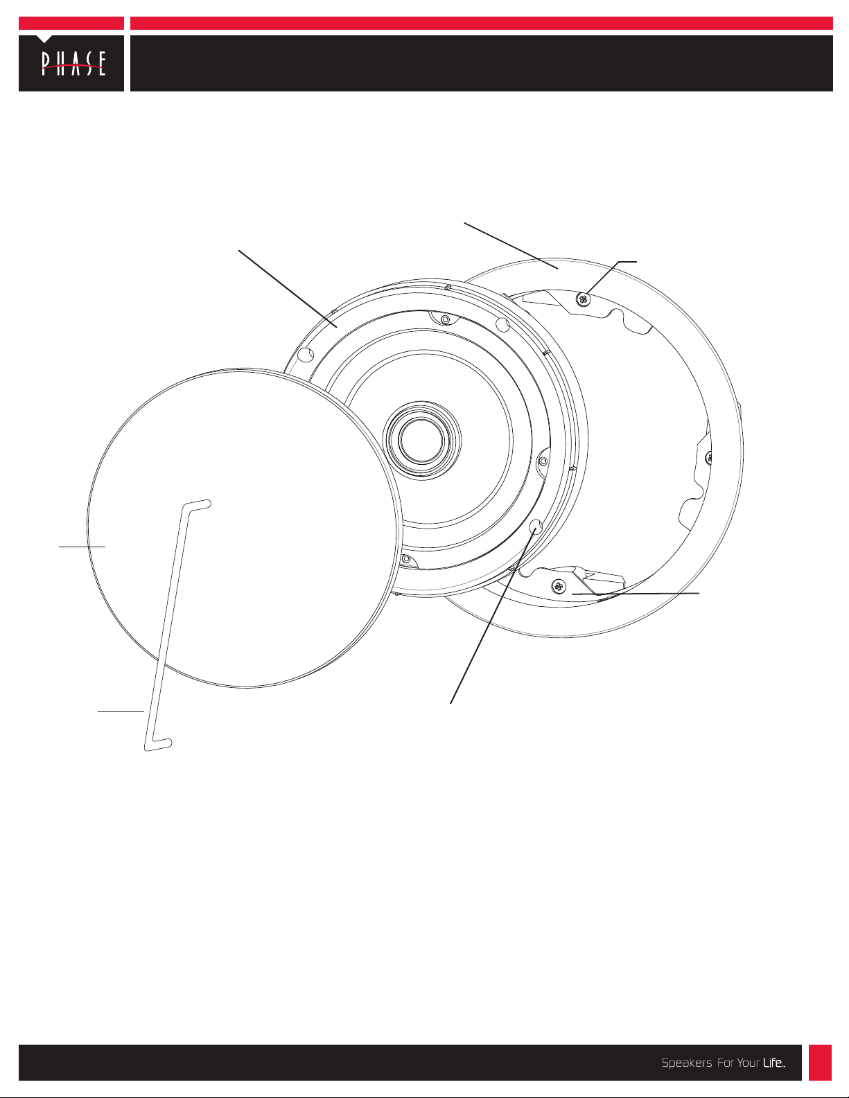
CI-6.0 IX QM
Speaker/baffle
assembly
Universal flange & grille
assembly (CI-FGR QM)
(purchase separately)
Flange clamp
screw (4x)
Grille
Speaker
installation tool
Baffle clamp screw (4x)
Choose the appropriate mounting location for each speaker.
When deciding upon a location, consider the following:
• Make certain your speaker wires can be run to or are accessible from these
locations.
• Make certain the wall or ceiling material is sturdy enough to support the
weight and vibration of the speakers.
• It is recommended that our pre-construction rough-in brackets (part number
RB-17*) be used whenever possible in new construction. A back box (part
number BB-12) is also available.
• Make certain the area behind the speaker is free of obstacles such as wall
studs, electrical wiring, pipes, etc.
• Each speaker should be positioned properly, relative to the listening area
for good coverage.
• Audio performance and room-to-room isolation will be improved if there is
some fiberglass insulation placed loosely behind the speaker.
Flange clamp (4x)
The CI-FGR QM will clamp
material up to 1
1
/2” thick.
*The RB-17 rough-in bracket is available for installations in new construction.
8650 College Boulevard | Overland Park, KS 66210 | (888)phase tk | www.phasetech.com | www.mseaudio.com
218-1240
Page 2
Install instructions for CI round flush mount models, Page 2
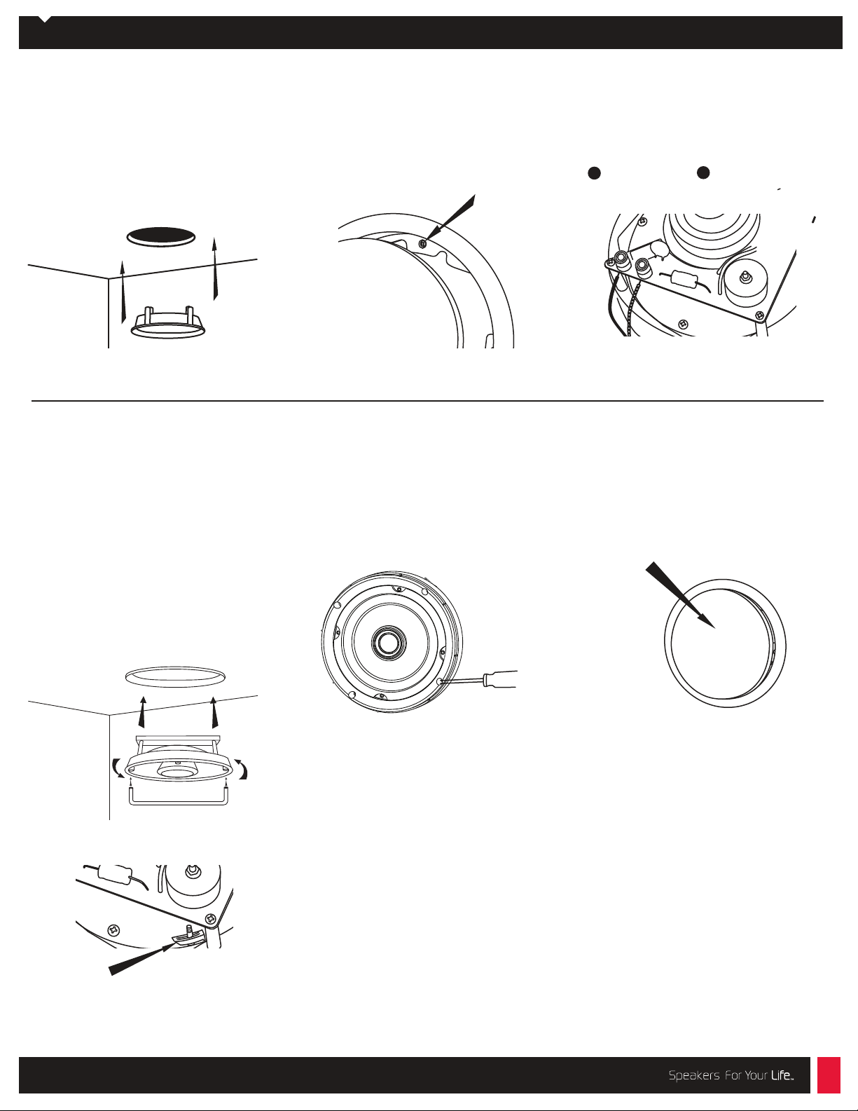
Flange Installation:
1. Using the supplied template, carefully
mark the area to be cut out. Using a
drywall knife or saw, cut a hole in the
drywall and prepare the speaker wires for
connection to the speaker terminals.
Remove the grille from the mounting
flange by pressing it from behind. Insert
the mounting flange into the hole.
4. Insert the speaker installation tool into
two of the screw access holes on the
speaker. Carefully place the speaker in the
flange; rotate slightly until the speaker
surface is even with or slightly recessed into
the surface of the flange. While exerting
upward pressure, use the tool to rotate the
speaker COUNTER-CLOCKWISE (left). This
will engage the QM SAFETY-LOC clamps on
the back of the flange. Remove tool and
tighten the four clamp screws on the
speaker. CAUTION: do not over-tighten.
2. Loosen the flange clamping screws one turn
(counter clockwise) to release the clamp. Next,
tighten all four flange clamp screws evenly to
secure the flange to the drywall. It is best to
tighten each screw with the same amount of
force (torque). CAUTION: Do not over-tighten.
NOTE: Special instructions for non-QM
Flanges
If you are installing a CI round speaker with
the QM clamps in a CI-FGR (non-QM flange)
remove the QM clamp feet by unscrewing
them from the speaker baffle. Insert the
speaker baffle into the flange and reuse the
screws from the clamp feet to attach the
speaker to the flange.
Speaker Installation:
3. Connect the speaker wires to the
spring-loaded input terminals on the rear of
the speaker, making sure no loose strands
are exposed.
+
Red/positive Black/negative
5. The tweeter may be aimed toward the
listening area by gently applying pressure
to the inside of the outer edge of the
tweeter assembly.
6. Carefully replace the grille by pressing it
into the gap between the flange and the
baffle. Enjoy your new Phase Technology
speaker!
Grille
_
CAUTION: Do NOT attempt to rotate the
speaker by grasping the tweeter!
SAFETY-LOC™ Clamp
8650 College Boulevard | Overland Park, KS 66210 | (888)phase tk | www.phasetech.com | www.mseaudio.com
 Loading...