

Page 1
Phase Technology 70Xi-APA/ APC/ ASL Analyzer System – Quick Installation Guide
1. Remove the following items from the 3 boxes:
70Xi analyzer box:
1 70Xi analyzer
1 accessory box:
- 1 AC power
cable
- 1 dryer bottle
Accessory box:
1 waste tank with grounding cable
1 box with solvent tank with grounding cable
1 box with pour sprout (level sensor attached)
1 bag of tubings and cables
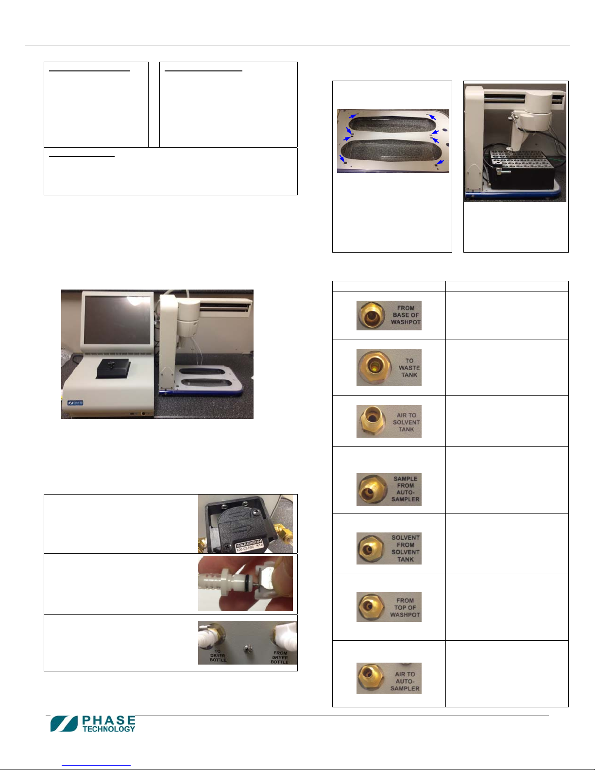
2. Set up the analyzer system:
The system should be set up:
- on a flat, vibration-free bench with room underneath
- in a well-ventilated location
Put the autosampler on the right side of the analyzer, with
the AC power cable connector facing the back.
Put the waste tank and solvent tank under the bench.
Autosampler box:
1 Autosampler
1 accessory box:
- 1 AC power cable
- 1 RS232 cable
- 2 vial heater/sample
(*APA & APC: 2 vial heaters)
(*ASL: 1 vial heater & 1 rack)
rack
5. Load the two vial heater/sample rack to the autosampler.
Make sure the 4 feet of each vial heater/sample rack sit
inside the square cutouts of the autosampler bottom tray.
8 square cutouts on the
bottom tray
6. Use wrench to connect the tubing to back of the analyzer:
Port at back of analyzer: Tubing:
“From Base of Wash Pot”
“To Waste Tank”
Vial heater/sample
rack on the bottom
tray (*put the vial
heater with wash pot
at front)
“From Base of Wash Pot”
Labeled
3. Remove 2 plastic caps and 7 swage caps on the back of the
analyzer, and 3 plastic caps at the solvent tank. Keep them
with the shipping boxes and related packing materials.
4. Connect the dryer bottle to the back of the analyzer:
a) Attach the dryer bottle to the
back of the analyzer by fitting
the two mounting bracket holes
over the two mounting screws.
b) Separate the quick-connect
fittings on the dryer bottle. Press
the latch on the female fitting
and pull them apart.
c) Attach the quick-connect fittings
to the “PURGE IN” and “PURGE
OUT” fittings on the back of the
analyzer. A “click” sound
confirms that the fittings have
snapped into place.
“Air to Solvent Tank”
“Sample From
Auto-Sampler”
“Solvent From
Solvent Tank”
“From Top of Wash Pot”
“Air to Auto-Sampler”
Labeled
“To Waste Tank”
Labeled
“Air To Solvent Tank”
Labeled
“Sample From Autosampler”
(the other end of the tubing
already attached to the
larger needle of the
autosampler probe)
Labeled “Solvent From
Solvent Tank”
Labeled
“From Top of Wash Pot”
(the other end of the tubing
already attached to top of
wash pot of the vial heater)
Labeled
“Air To Autosampler”
(the other end of the tubing
already attached to the
smaller needle of the
autosampler probe)
Page 1 of 3 Customer Service & Support: 604-241-9568
customer_service@phase-technology.com
Page 2
Phase Technology 70Xi-APA/ APC/ ASL Analyzer System – Quick Installation Guide
7. Use wrench to connect the tubing to the autosampler:
Port at autosampler: Tubing:
Elbow fitting at bottom of
wash pot of vial heater
Labeled
“Bottom of Wash Pot”
Vent port at front of wash pot
of vial heater
8. Use wrench to connect the tubing to solvent tank:
Port label at solvent tank: Tubing label:
“Air In” “Air In”
“Solvent Out” “Solvent Out”
“Vent” “To Solvent Tank Vent”
9. Remove the cap of the waste tank, and carefully screw in the
pour sprout (with level sensor attached).
10. Use wrench to connect the tubing to the waste tank:
Port at waste tank: Tubing:
Any of the
available ports
11. For the 2 vent tubes from the solvent tank and waste tank,
direct the open end to a well-ventilated area such as an
exhaust fume-hood. Exhaust liquid/fume s can emerge from
these ports.
12. Connect the vial heater block vent tube to the waste tank. If
this is not possible, direct the vial heater block vent tube to
the exhaust. Install a cap on the waste tank barb fitting if
directing the vial heater block vent tube to the exhaust.
13. Connect the sensor/heater cables to the back of the analyzer:
Port label at back of analyzer: Cable label:
“Transfer Tube Heater” “To Transfer Tubing Heater”
“Level Sensor” “To Level Sensor”
“Heater Block 1” “Heater Block 1”
“Heater Block 2” “Heater Block 2”
14. Connect the sensor cables to the solvent and waste tank:
Tank: Cable label:
Solvent: “Level Sensor” port
with cable labeled “S”
Waste: Cable labeled “W” “W”
½” OD tubing without
label (may have already
attached to the vent port)
“From Wash Pot To Waste Tank”
“To Waste Tank”
“To Waste Tank Vent”
“S”
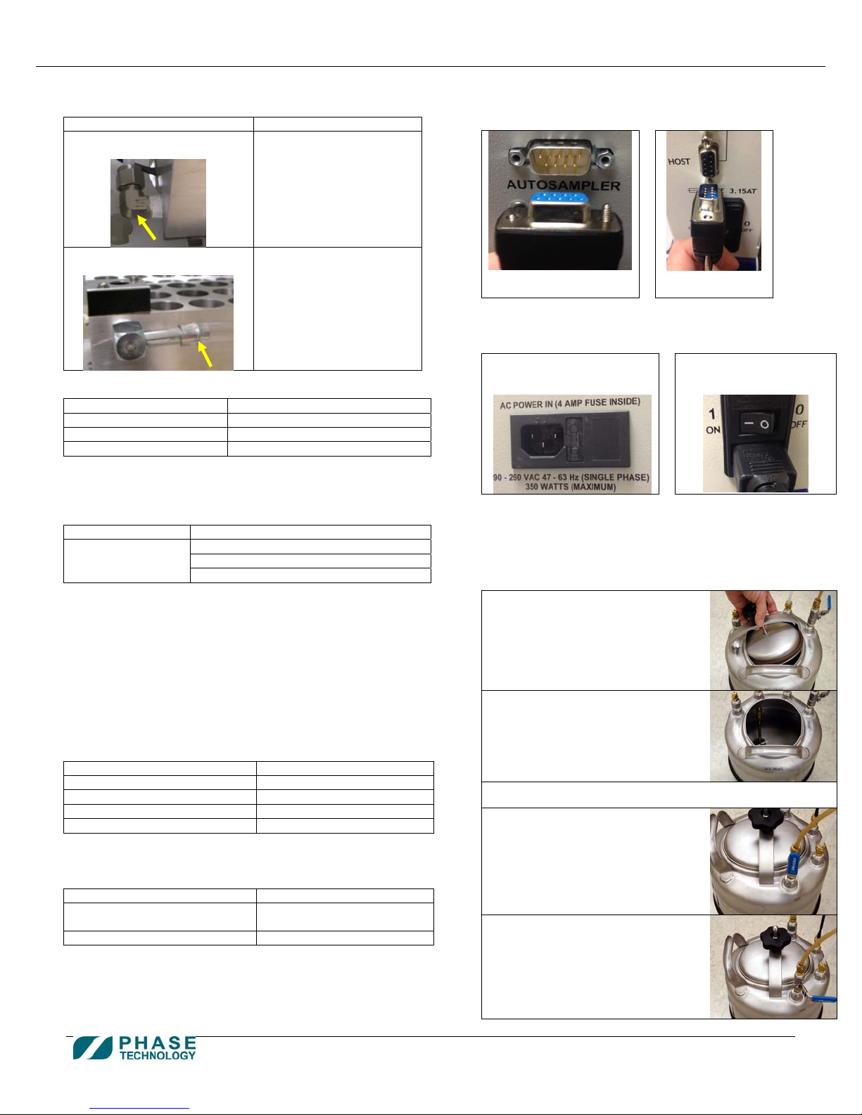
15. Connect the RS232 cable from the “AUTOSAMPLER” port on
the back of the analyzer to the “HOST” port of the
autosampler.
“AUTOSAMPLER” port on
back of the analyzer
16. Connect the AC power cables:
a) Connect the AC power
cable to the back of the
analyzer
Plug the power cables into a grounded AC outlet that is a
dedicated circuit. If the power source is unstable or noisy,
use a power surge protector, equipped with a line filter.
17. Fill solvent tank with Heptane:
a) Lift the handle on the solvent
tank lid to unlock the lid.
b) Remove the lid from the solvent
tank.
c) Fill the solvent tank with Heptane.
d) Replace the lid and push the
handle down to lock it. Before
locking it, ensure that there is
equal spacing around the entire
lid between the lid and the tank
for proper sealing.
e) Push the ball-valve handle down
to the horizontal position.
“HOST” port of
the autosampler
b) Connect the AC power
cable to the back of
the autosampler
customer_service@phase-technology.com
Page 2 of 3 Customer Service & Support: 604-241-9568
Page 3

Phase Technology 70Xi-APA/ APC/ ASL Analyzer System – Quick Installation Guide
18. Power up the analyzer:
Press the round button at the bottom right hand side at the
front of the analyzer.
- The analyzer will perform a set of self tests to verify
its main components, including the optics system
and cooling system, are operating correctly.
- If a problem is detected, the self tests will stop and a
message will be displayed on the bottom of the
screen.
- If any component fails the self tests, press the
INTELLINOSTICS button for further
information and troubleshooting steps.
- If the pour point function is available, the analyzer
will automatically perform an auto-purge process
19. Power up the autosampler:
after the self tests.
Switch the power control above the power cable connector
to the “I” position.
- The autosampler will perform a series of self-tests,
moving its arm to pre-defined locations.
Warning: The arm moves and rotates at a
moderately fast speed during its self-tests.
The tip of the autosampler probe is sharp.
Caution: Do not place obstacles that would
block or impede the movement of the arm. If
the arm movement is impeded at any point
during the self-test causing it to stop or
stutter, switch off the autosampler and
20. After the self-tests are completed, the analyzer shows
the Vial Setup screen.
power it on again to reinitialize.
- The analyzer returns to this screen whenever
the VIAL SETUP button is pressed.
- The Sample Cup Temperature, Optics Light Signal,
and Run Count are displayed at the top of the
screen.
- A set of Favorites buttons is listed on the right hand
side of the screen.
- The main area in the middle of the screen is used for
programming test settings for any vial position. The
rows of circles represent the physical vial positions
available on the two vial racks of the autosampler.
- The ACCESS button on the lower left ha nd
corner is used for changing user access levels,
resetting the analyzer, and shutdown.
21. Pressurize the solvent tank:
Press “Analyzer Options” on the Toolbar at the
bottom of the analyzer screen.
On the Analyzer Options screen, press “Pressurize
Solvent Tank”.
On the Pressurize Solvent Tank screen, press “S tart
Pressurizing Solvent Tank”.
The pressurization will automatically stop once the
target pressure is reached, or if the tank failed to
pressurize (due to the lid not closed properly, or the
handle of the ball-valve is still in vertical position).
Once the pressurization has successfully completed,
press “Close” and the analyzer is now ready for
testing.
22. To start a test:
a) Fill a vial with sample to ¾ full. Insert a septa
inside the vial cap (Teflon side facing the sa mple),
and screw the vial cap onto the vial. Place the v ial
into any available position on the sample rack.
b) To program a vial using a
predefined test setting,
simply drag a suitable
favorite button to the vial
position where the
corresponding test sample
has been placed on the
sample rack.
c) Repeat the drag & drop
procedure if more than one vial needs to
be programmed. After all vials have been
programmed, press the START TEST
button to start the test sequence.
customer_service@phase-technology.com
Page 3 of 3 Customer Service & Support: 604-241-9568
 Loading...