

Page 1

Owner’s Manual
CA-1000
CONTROL AMPLIFIER
Page 2

Page 3

3
Table of Contents
Safety Instructions...................................................................................................4
Usage Cautions.......................................................................................................5
Care of Equipment...................................................................................................5
Names and Functions.........................................................................................6 - 11
Control & Power Section..................................................................................6 - 8
Amplifier Section..............................................................................................9, 10
Remote Controller................................................................................................11
Connections...........................................................................................................12
Trouble Shooting Guide..........................................................................................13
User Support.......................................................................................................14
Specifications.........................................................................................................14
Thank you for purchasing Phasemation product.
Read your Owner’s Manual thoroughly for proper operation before starting to
use your equipment.
Please keep your Owner ’s Manual with caution.
Page 4
4
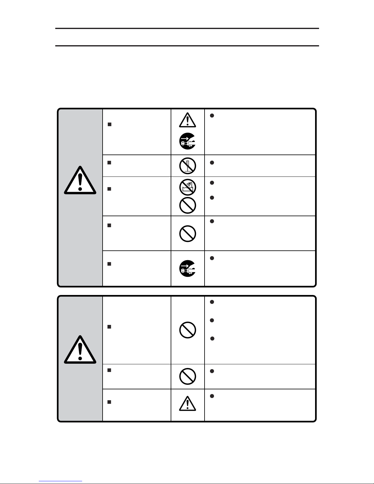
Safety Instructions
WARNINGS
CAUTIONS
Before starting
to use
In this owner’s manual and on the product, various pictures are used
to show our customers how to use Phasemation CA-1000 safely and
properly in order to avoid the loss of customer’s assets and to protect
our customers from harm.
Do not use the
equipment being
broken.
Never remodel the
equipment.
Never install the
equipment near
water.
Never put an object
filled with water on
the equipment.
Never put an object
inside the equipment.
Cautions of
Installation
Places which are not
suitable for
installation
Connection
In case of using the equipment in an abnormal
state, such as seeing smoke, having strange
smell or hearing unusual sounds or noises, this
can result in a risk of fire or electric shock. If
such an abnormal state occurs, turn the power
switch off and endure to disconnect the AC plug
from the outlet. After no smoke is confirmed, ask
the dealer for the repair.
Do not disassemble the equipment or remodel
it. This can result in a risk of fire.
Do not use the equipment in the bathroom. This
can result in a risk of fire or electric shock.
The equipment is designed for using indoors.
Do not expose the equipment to water. This can
result in a risk of failures, fire and electric shock.
Do not put a vase, flower pot, glass or any
object filled with skin lotion, chemical substance
or water, or small metal objects on the
equipment. In case the liquids are spilled or the
small objects fall inside the equipment, this can
result in a risk of fire or electric shock.
If a foreign object has fallen inside the
equipment, turn the amplifier’s power switch off
and contact the dealer. To keep using the
equipment can result in a risk of fire or electric
shock.
Do not install the equipment in the humid or
dusty environment. This can result in a risk of
fire or electric shock.
When connecting with other audio equipments
or a television set, read the manual of the
equipment, turn the power switch off, and
connect according to the instructions.
Do not install the equipment on the unstable
tables or unstable places. In case the equipment
falls, it can result in a risk of injury of customers.
Pay attention to the wiring of the cord so that a
foot is not caught or the person can stumble or
the equipment can fall, which is so dangerous.
When moving the equipment, turn the power
switch off and endure to disconnect the power
plug from the outlet and remove the connecting
cord. The cord can be damaged and this can
result in a risk of fire and electric shock.
Page 5
5
Installation place
Useable AC power supply voltage and frequencies
Repair
Handling the AC power cable
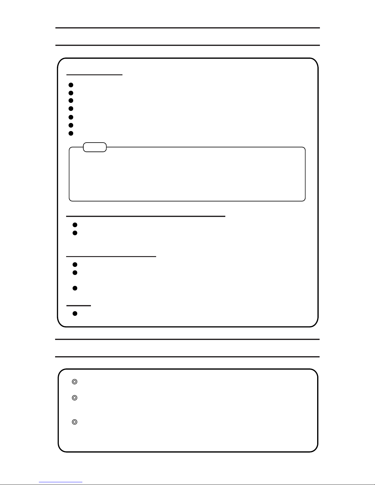
Usage Cautions
Care of Equipment
Note
In order to use the equipment for a long time, follow the instructions
shown in below:
Do not install this equipment near a heat source such as direct sun light, a stove and so forth.
Do not use this equipment at a poorly-ventilated, humid or dusty place.
Do not install this equipment at an unstable place such as a slope or vibrating place.
Do not install this equipment near the window where the equipment can be exposed to rain.
Do not install this equipment in a high humid environment.
Avoid using this equipment on equipments generating heat such as an amplifier.
Keep this equipment away from a power supply transformer or a motor of an other equipment.
AC 230V power supply must be supplied.
The equipment operates normally in both areas of the 50Hz and 60Hz power supply frequen
-
cies.
Do not touch the AC power cable with wet hands.
Do not pull the cable strongly or bend the cable. The cable can be damaged and can result in
a risk of fire or electric shock.
Use the AC power cable of the accessories.
If the equipment is covered with dust or dirt, clean it with a soft cloth.
If the equipment is covered with heavy dust, put a very thin mild detergent on a soft cloth.
Wring the cloth and wipe off the dust and dirt. Then clean with a dry soft cloth.
Never use chemical agents such as thinner, naphtha or alcohol when cleaning it.
If any of them is attached to the equipment, the silk printing can be flaked or the surface can
lose metal luster.
In case of the equipment failure, consult the dealer.
Avoid covering the equipment with cloth or installing it in an enclosed space because
radiation and air convection from the chassis surface can be hindered.
At the amplifier section, to prevent external sound pressure, grit and dust from entering
the equipment, inspiratory/exhaust ports to radiate the heat are not arranged against the
equipment consciously. Radiating the heat from the equipment is realized by cooling it
with air convection in the chassis and with radiation and air convection from the chassis
having high thermal conductivity.
Page 6
6
Names and Functions
Control & Power Section
Front Panel
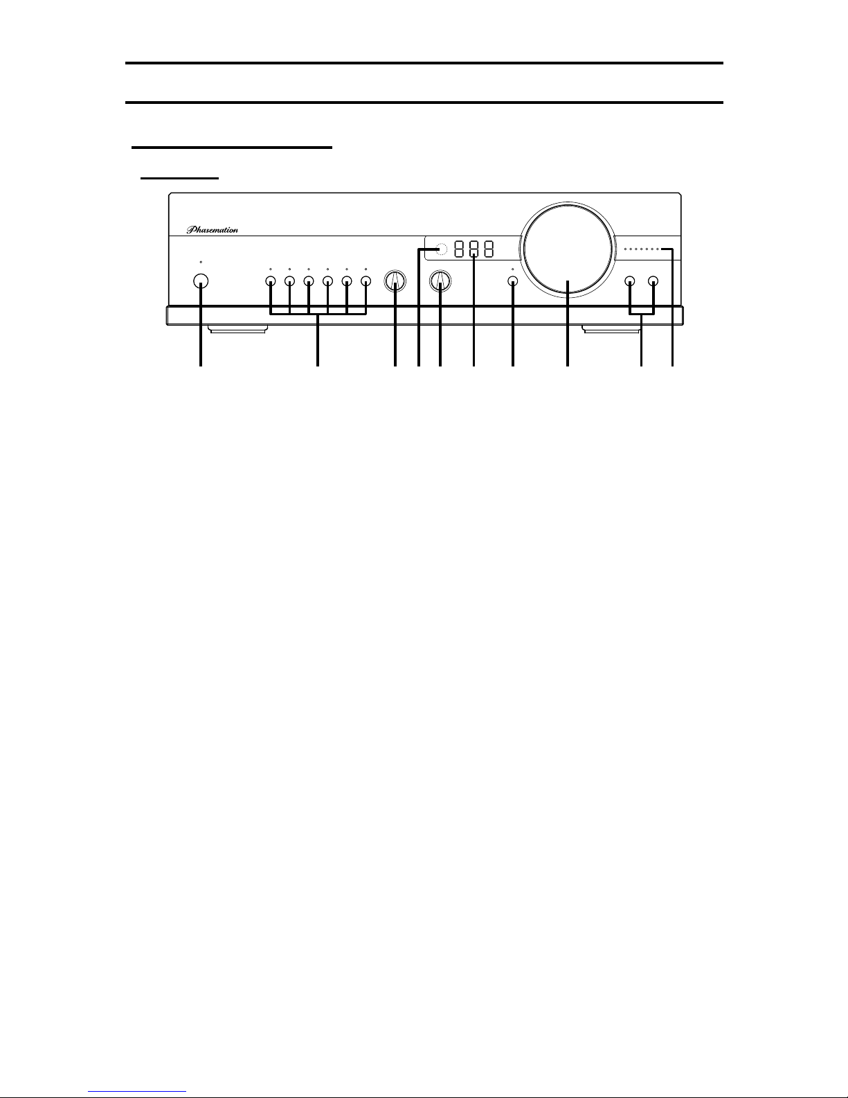
This switch turns the power ON or OFF. After this switch is pressed to turn it to ON, a
blue indicator lights up and then, ‘30’ is displayed on (6) DISPLAY and it starts to count
down. While it is counting down, the product enters the ‘STANDBY’ mode and the other
functions and indicators are temporarily stopped. After the countdown finishes, the
control amplifier functions become available at the condition with each part being main
-
tained before it was turned off.
(1) POWER switch/indicator
These respective switches select the desired input source to be played. The blue
indicator corresponding to the selected source lights up. The condition of the selected
input source is stored so even after the power is turned to OFF and ON, the same
source is selected.
(2) INPUT SELECTOR switches/indicators
This switch selects the desired amplifier gain as follows:
–6: Decreasing 6dB from the standard level
0: LEVEL 0dB (Standard level: 12dB)
+6: Increasing 6dB from the standard level
(4) LEVEL selection switch
This portion receives the light from the remote controller.
When installing the product, do not place an object disturbing the light between this portion and the remote
controller.
(5) Remote controller reception portion
This switch selects the desired output terminal as follows:
OFF: Not outputted
1: Unbalanced output through the RCA pin connector
2: Balanced output through the XLR connector
1+2: Both of them at the same time
(3) OUTPUT selection switch
–6 +6
0
CA-1000 CONTROL AMPLIFIER
OFF
1+2
BALANCE
RL
VOLUME
MUTE
OUTPUTINPUT
2
1
654321
POWER
LEVEL
(1) (3) (4) (6) (9)(5) (7) (8)(2) (10)
Page 7

7
This displays the attenuation (dB) of the attenuator; however, ‘– 99’ is close to nothing.
(6) Display portion
This knob controls the audio volume and the volume is increased by turning it right
(clockwise) and decreased by turning it left (counterclockwise).
(8) VOLUME knob
These indicate the setup due to the (10) BALANCE switches.
The center is blue and the other six are orange.
(9) BALANCE indicators
These switches adjust the volume difference between L-ch and R-ch. A maximum of a
three-step difference between L-ch and R-ch master-volume step can be set and the
setup is indicated by (9) BALANCE indicators.
* The difference is made by decreasing one of the master-volume steps of L-ch
and R-ch.
Example: When the center indicator (blue) lights up, when R-ch switch is
pressed once, the L-ch volume is decreased by one step.
* When the outside end indicator lights up, when that switch is pressed, the
indicator is changed from lighting-up to flashing and the other channel volume
level is changed to 0-step. (This operation is utilized for checking respective
channels.)
(10) BALANCE switches
This switch mutes the audio output and this indicator lights up. Then by pressing this
switch again, the muting mode is cancelled and the audio output is returned to the
previous level. The same operation can be controlled by using the MUTE switch of the
remote controller.
The ATT switch on the remote controller decreases the audio volume by 20dB from the
displayed level and this indicator flashes. Then by pressing the ATT switch again, the
attenuation mode is cancelled.
* The muting mode or the attenuation mode is cancelled by pressing the VOLUME UP,
VOLUME DOWN or BALANCE switch.
(7) MUTE switch/indicator
Page 8
8
Rear Panel
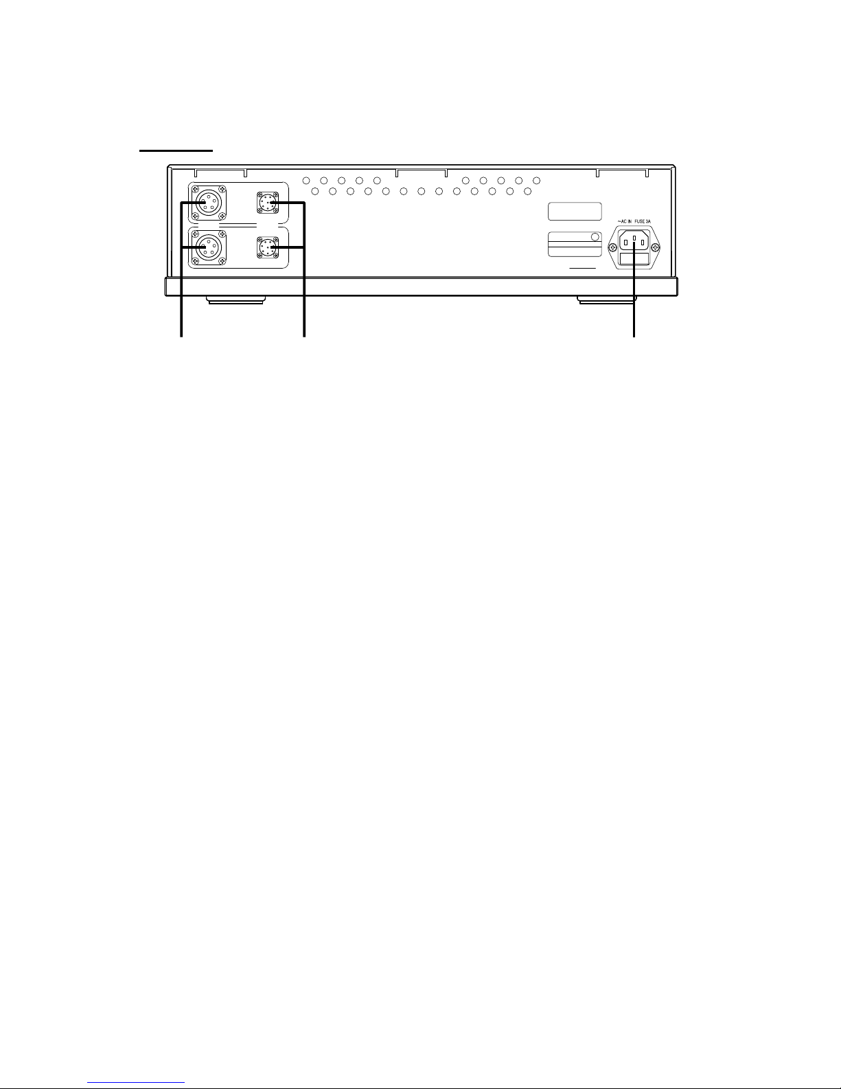
Connect these to the amplifier section.
(11) DC OUT terminals
Connect these to the amplifier section.
(12) CONTROL OUT terminals
Connect this to your AC outlet through the AC power cable of the accessories.
(13) Power inlet
Lch
Rch
CONTROL
OUT
DC OUT
SER.NO.
E
SP
CAUTION !
RISK OF ELECTRIC SHOCK
DO NOT OPEN
MODEL CA-1000
230V 50/60Hz 43W
KYODO DENSHI ENG CO.,LTD.
MADE IN JAPAN
(13)(11) (12)
Page 9
9
Amplifier Section
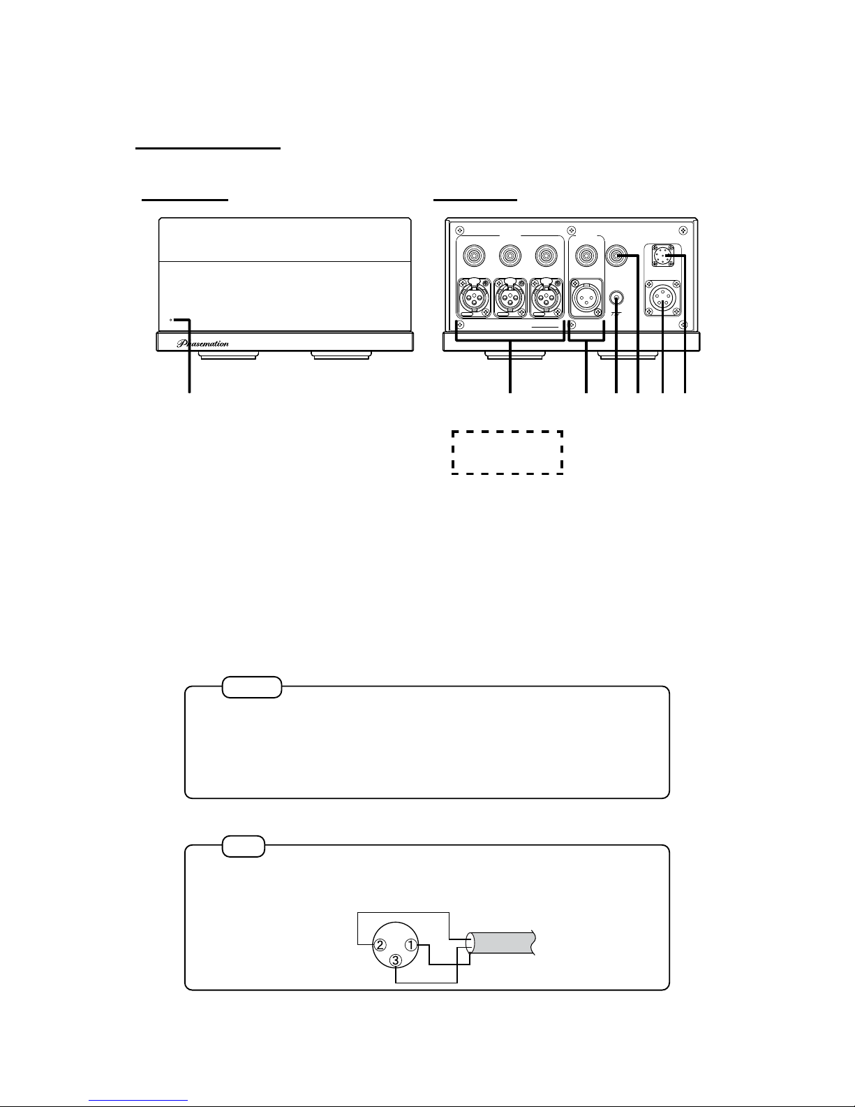
Front panel Rear panel
Caution
Note
The XLR terminal is adopted as a balanced terminal of INPUT for this product.
Pin assignment is as follows: pin-1: GND, pin-2: HOT and pin-3: COLD.
GND
HOT
COLD
Lch:
C1*******L
White RCA connector
Rch:
C1*******R
Red RCA connector
Serial No.
This indicator lights up blue when the power is ON.
(14) POWER indicator
Unbalanced input terminal of the RCA connector (INPUT 1, 2 and 3)
Balanced input terminal of the XLR connector (INPUT 4, 5 and 6)
(15) INPUT terminals
21
3
1
2
3
NEUTRIK
PUSH
SER.NO.
ATT
OUT
OUTPUT
INPUT
2
11 2 3
4 5 6
GND
MODEL CA-1000
KYODO DENSHI ENG CO.,LTD. MADE IN JAPAN
DC IN
CONTROL IN
1
2
3
NEUTRIK
PUSH
1
2
3
NEUTRIK
PUSH
CA-1000
(14) (18)
(17)
(20)
(19)
(15) (16)
The balanced input circuit contains a transformer for this product. When the
bal anced s yst em to w hic h a unb alanc ed sy ste m is co nve rted by s ome
co nv er si on a da pt or i s in pu tt ed t o the balanced input of this product, the
original performance cannot be realized.
For the balanced input of this product, connect a balanced output.
Page 10
10
Caution
Note
HOTGND
COLD
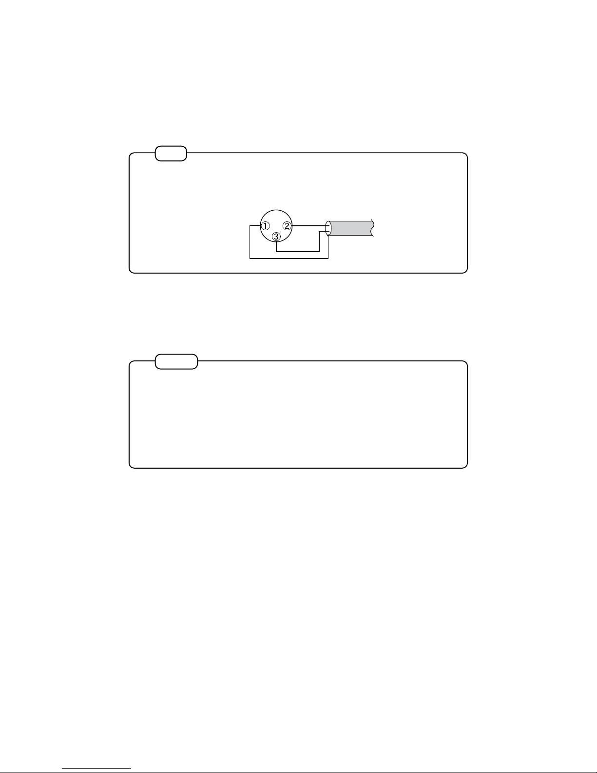
For a ny eq uip men t con nec ted t o thi s pro duc t thro ugh t he RC A or XLR
connector, do not connect this GND terminal to it as earth; otherwise, an earth
loop formed between the equipment and this product deteriorates the sound
quality.
If necessary, utilize this GND terminal for a ground circuit separated against
an audi o signa l cir cu it, s uch as fo r a motor e arth of a n ana lo g pla yer, a
chassis of a MC step-up transformer, or earth.
This is the unbalanced output terminal to which the signal is directly outputted from the
built-in passive attenuator without passing through the amplifier section.
(18) ATT OUT terminal
Connect this to the control & power section.
(19) DC IN terminal
Connect this to the control & power section.
(20) CONTROL IN terminal
The XLR terminal is adopted as a balanced terminal of OUTPUT for this
product.
Pin assignment is as follows: pin-1: GND, pin-2: HOT and pin-3: COLD.
Unbalanced output terminal of the RCA connector (OUTPUT 1)
Balanced input terminal of the XLR connector (OUTPUT 2)
(16) OUTPUT terminals
This is the reference earth point for the audio system.
(17) GND terminal
Page 11
11
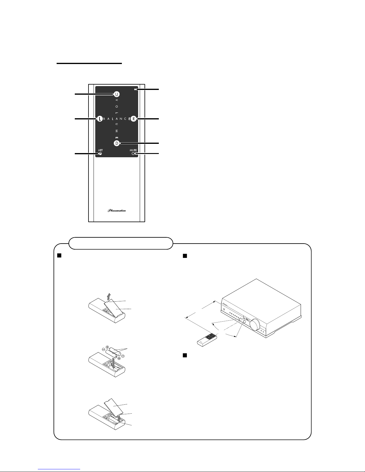
Usage of Remote Controller
Operational distance of the remote controller
The operational angle of the remote controller is 60 degrees in upper,
lower, right, and left, an
d the operational distance is within 5m.
Cautions for using the remote controller
Battery lid
60°
5m
Upper notch
Battery lid
AA dry battery
Lower notch
Hook of main body
Remote Controller
(21)
(25)
(24)
(22)
(27)
(23)
(26)
Setting dry batteries in the remote controller
Before using the remote controller of the accessories, new dry
batteries should be set. The batteries of accessories are for
confirming the operation of the remote controller.
1. Lift the upper notch of the battery lid towards the arrow direction
and remove it.
2. Set the two new AA dry batteries as shown below with being
careful about the polarities (direction of +: plus and –: minus).
3. Attach the lower notch of the battery lid to the hook of the main
body and fit the battery lid to the main body.
(21) VOLUME switch (UP)
Increases the audio volume.
(22) VOLUME switch (DOWN)
Decreases the audio volume.
(23) BALANCE switch (LEFT)
Shifts the balance to the left.
(24) BALANCE (RIGHT)
Shifts the balance to the right.
(25) LED
Flashes when some switch is pressed.
(26) ATT switch
Decreases the volume by 20dB.
(27) MUTE switch
Mutes the audio output. (No sound)
•
Never expose the remote controller reception portion to
intense light such as a direct sunlight or an inverter type
fluorescent lamp. The operation of the remote controller may
become invalid.
•
Note that the IR ray causes equipment controlled by the IR ray
to malfunction when operating the remote controller.
•
In case that an object is placed between the remote controller
and remote controller reception portion, the operation
becomes invalidy.
•
Do not place an object on the remote controller, or the batteries
are consumed because some switch continues to be pressed.
Page 12
12
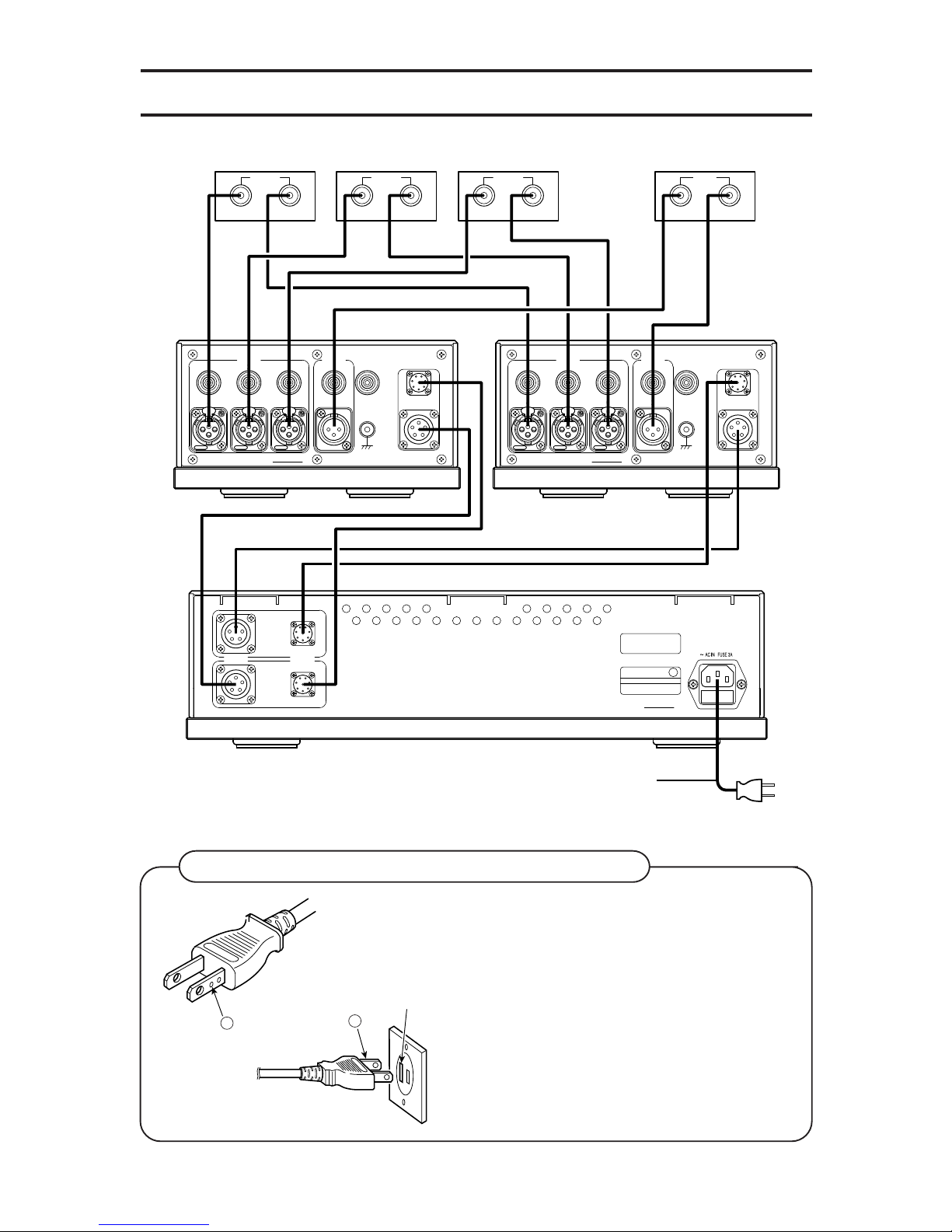
Connections
Long slot
Side assigning
the circle
Circle
Plugging the plug of AC power cable in an outlet
A circle is assigned on the one side of the plug of
the AC power cable so that better quality sound is
reproduced by matching the power supply polarity
with other equipments.
Thi s pol a rit y may b e dif fer ent b e cau se of t he
hous e w irin g f or the o u tlet o r b ecau s e o f the
power supply conditi on; however, gen erally the
side assigning the circle should be inserted to the
long slot of the outlet.
Lch
Rch
CONTROL
OUT
DC OUT
SER.NO.
E
SP
CAUTION !
RISK OF ELECTRIC SHOCK
DO NOT OPEN
MODEL CA-1000
230V 50/60Hz 43W
KYODO DENSHI ENG CO.,LTD.
MADE IN JAPAN
21
3
1
2
3
NEUTRIK
PUSH
SER.NO.
ATT
OUT
OUTPUT
INPUT
2
11 2 3
4 5 6
GND
MODEL CA-1000
KYODO DENSHI ENG CO.,LTD. MADE IN JAPAN
DC IN
CONTROL IN
1
2
3
NEUTRIK
PUSH
1
2
3
NEUTRIK
PUSH
21
3
1
2
3
NEUTRIK
PUSH
SER.NO.
ATT
OUT
OUTPUT
INPUT
2
11 2 3
4 5 6
GND
MODEL CA-1000
KYODO DENSHI ENG CO.,LTD. MADE IN JAPAN
DC IN
CONTROL IN
1
2
3
NEUTRIK
PUSH
1
2
3
NEUTRIK
PUSH
OUTPUT
RIGHT
LEFT
OUTPUT
RIGHT
LEFT
OUTPUT
RIGHT
LEFT
AC Power Cable of Accessories
CD player Phono amplifier FM tuner
INPUT
RIGHT
LEFT
Power amplifier
Page 13
13
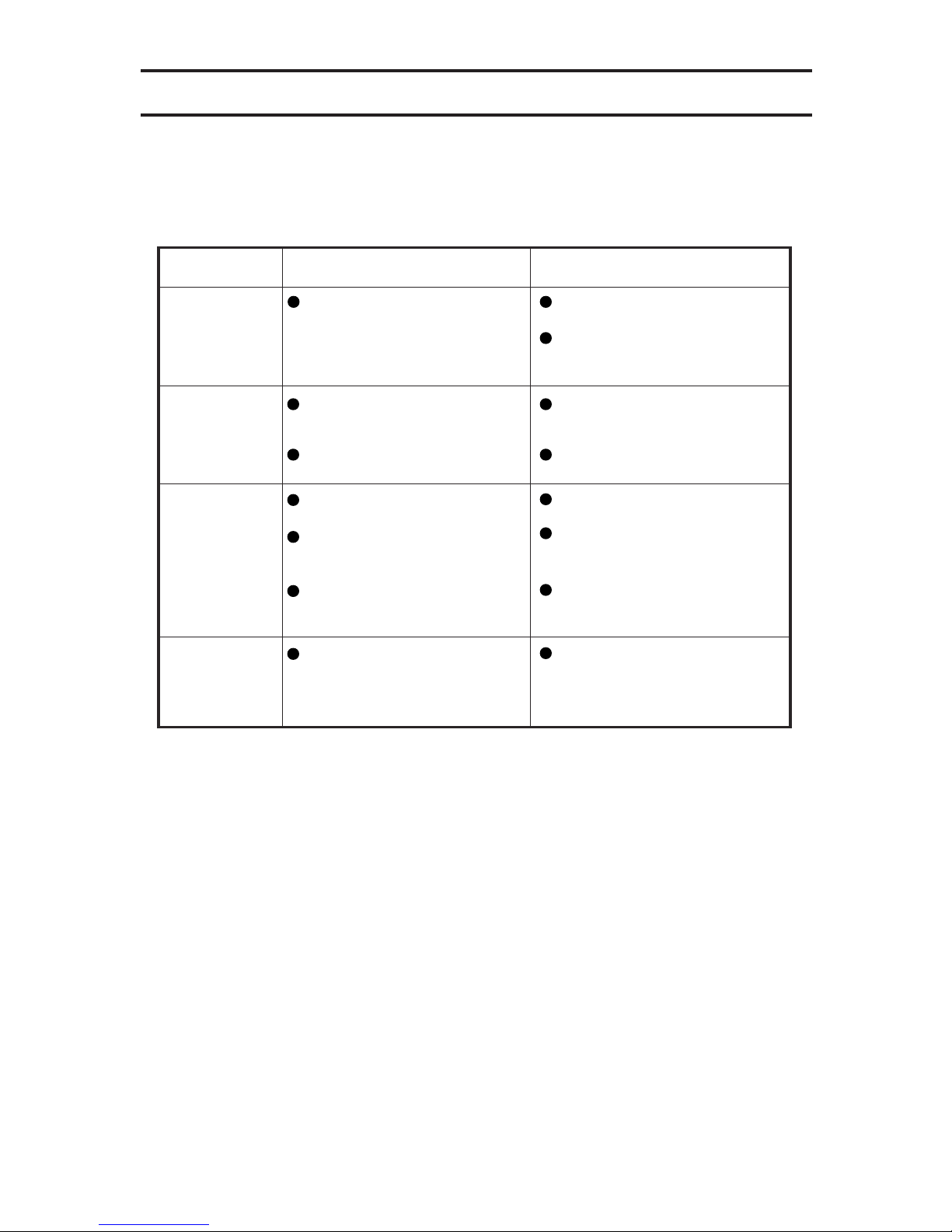
Trouble Shooting Guide
Trouble
Causes
Measures
The power is not
supplied.
In case the equipment does not operate properly, check out the followings.
If it does not operate properly even after checking the advised points, endure to
disconnect the AC plug from the outlet and then contact the dealer.
The sound is not
heard.
Hum noise is
heard.
Sound is not
heard immediately
after turning the
power on.
The plug of the AC power cable
is not plugged in completely.
The audio wires are not plugged
in completely.
The output selector is set to OFF
The vacuum tubes are worked in
the equipment.
Sound is not outputted until the
circuits come to stable operation.
The audio wires are not plugged
in completely.
The earth cable from the
analogue disc player is not
connected.
A power supply transformer or
motor in an other equipment is
installed near this equipment.
Insert the plug of the AC cable into
an outlet firmly.
Firmly insert the outlet of the AC
power cable into the AC inlet of the
power equipment.
Insert the audio wires completely.
Set it to the desired output terminal.
After starting to count down from
30 on the display panel, wait until
it finishes. (About 30 seconds)
Insert the audio wires completely.
Connect the earth cable completely.
Place this equipment apart from
the power supply transformer or a
motor of an other equipment.
Page 14
14
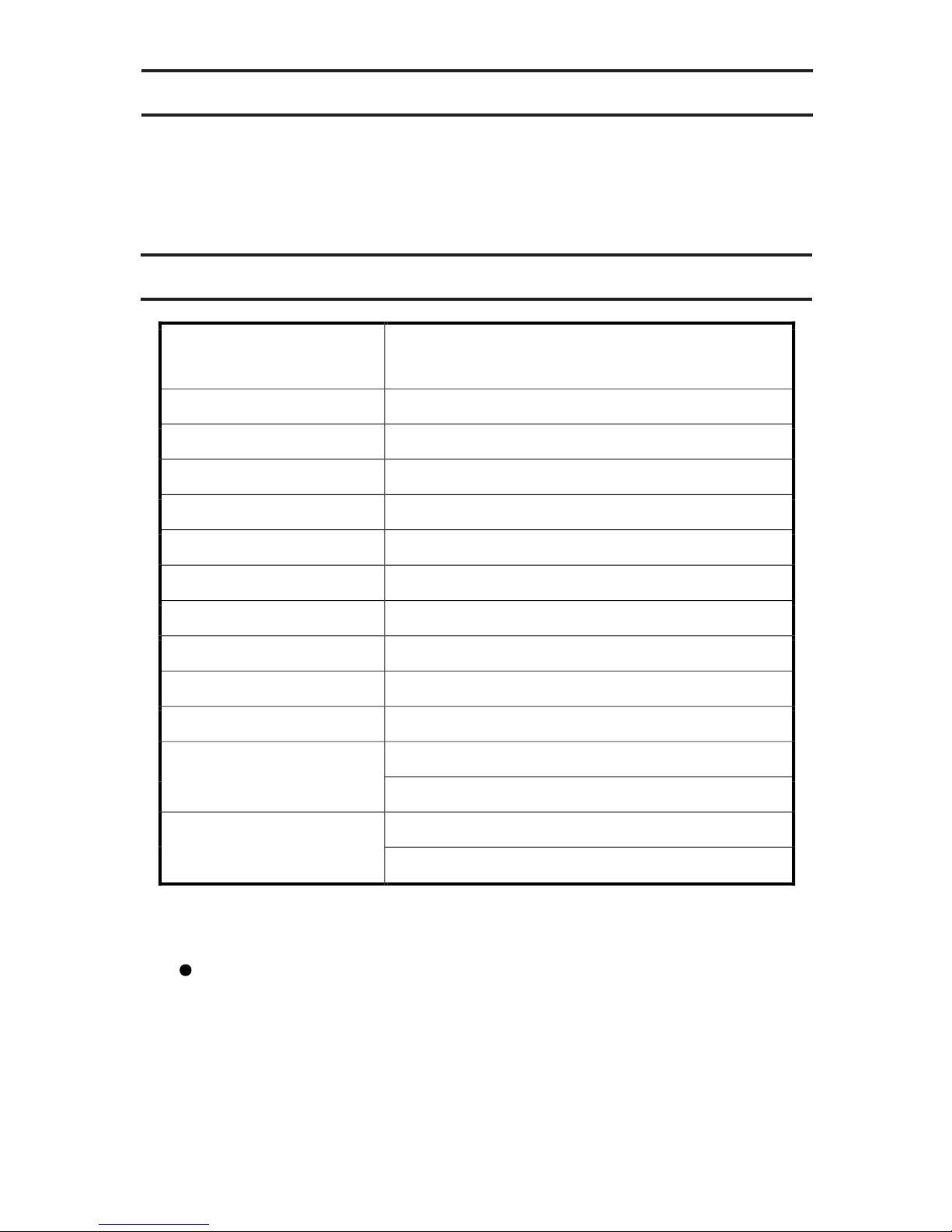
Specifications
User Support
As for the unclear matters with regards to the after service, please contact the dealer.
The appearance and specifications of this equipment are subject to change without notice in order
to improve it.
Product
Input sensitivity
500mV/1000mV (RCA/XLR))
Input impedance
47k-ohm
Gain
Standard (12dB), Standard ±6dB
Equivalent input noise
–100dBV (10µV): A-NET
Channel separation
100dB or more (20Hz to 20kHz)
Rated output voltage
2.0V (1kHz)
Frequency characteristics
20Hz to 20kHz (±0.5dB)
Output impedance
100 ohm or less (for balanced and unbalanced type)
Power consumption
43W (100VAC, 50 to 60 Hz)
Input/Output terminals
Made by WBT and NEUTRIK
Dimensions (mm)
Control & Power section: 434(W) × 118(H) × 374(D)
Amplifier section: 214(W) × 118(H) × 355(D)
Weight
Control & Power section: 14kg
Amplifier section: 7.5kg x2
Tube type Control Amplifier which is separated in
to three units and has the impedance-matching-
volume adjustment circuit
Accessories: DC power relay cable x2, Control communication cable x2
GND cable x1, AC power cable x1, Remote controller x1, Battery x2
Page 15

Page 16
Kyodo Denshi Engineering Co., Ltd.
Ikebe-cho 4900-1 Tsuzuki-ku Yokohama-shi Kanagawa 224-0053 Japan
TEL 045-934-5234
FAX 045-934-7576
E-mail [email protected]
URL http://www.phasemation.com
is the original audio brand of Kyodo Denshi Engineering Co., Ltd.
 Loading...