

Page 1
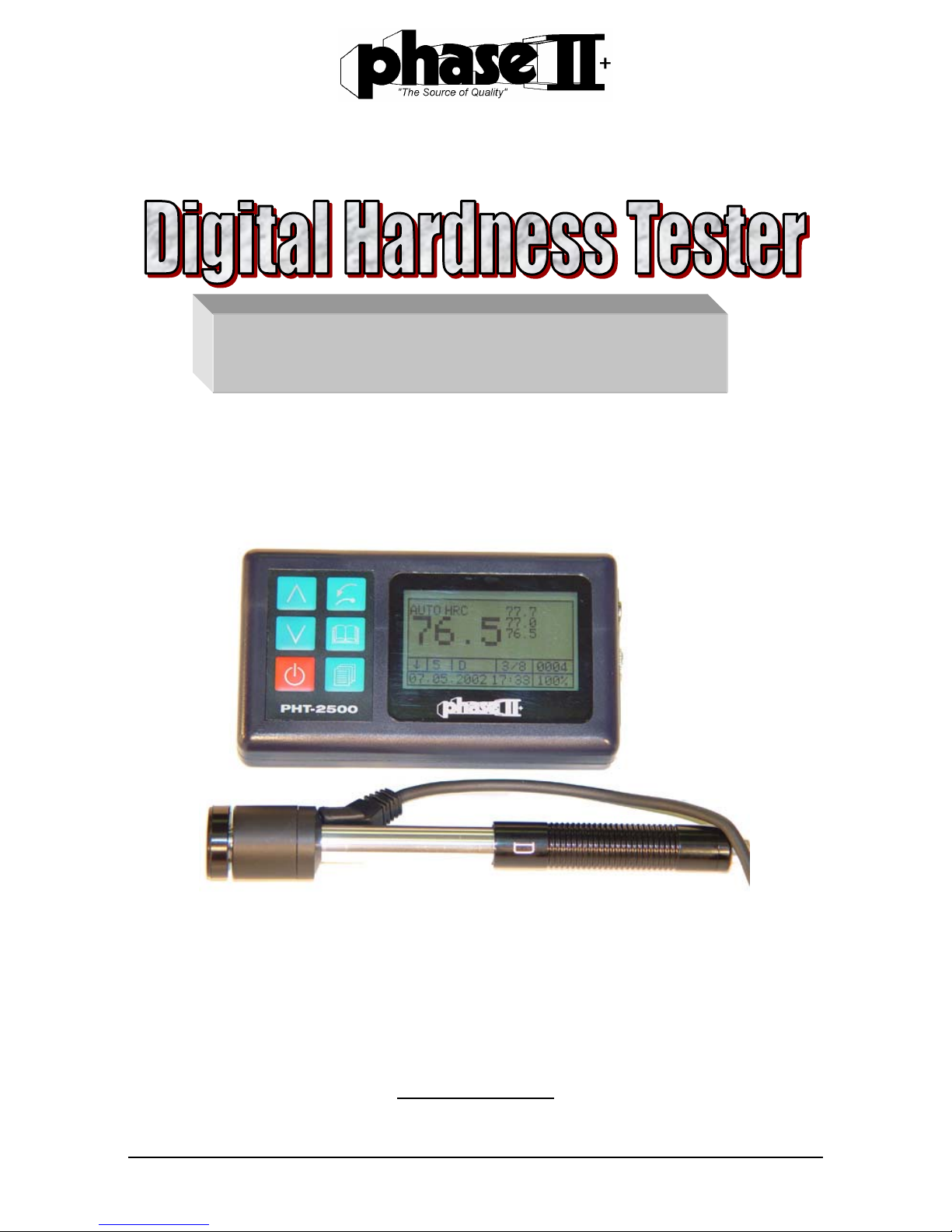
Model # PHT-2500
Instruction Manual
(201)933-6300
www.phase2plus.com
* Precision Measuring Tools * Indexing Fixtures * Workholding Fixtures *
* Hardness Testers * Ultrasonic Thickness * Surface Finish * Coating Thickness *
Page 2

2. FUNCTIONS OF THE PHT-2500 HARDNESS TESTER 2
2.1. Typical Applications 2
2.2 Technical Data 2
2.3 Available Functions 3
2.4 Measuring and Converting Ranges 3
* Impact device parameters 3
3. LEEB MEASURING METHOD 5
3.2 Leeb’s Hardness Tester (definition) 5
3.3 Notation of Leeb’s Hardness 6
3.1 History 5
4. PRETREATMENT OF SAMPLES 6
4.1 Pretreatment of Sample Surface 6
4.2 Curving Surface 6
4.3 Supporting a Test Sample 7
4.4 Large Test Samples 7
4.5 Test Sample Properties 7
5. KEYPAD FUNCTIONS 8
6. OPERATIONS OF THE INSTRUMENT 8
6.1 Starting 8
6.2 Setting of all testing Parameters
Setting impact direction 9
Obtaining an Average 9
Selecting a Material 9
Choosing A Hardness Scale 9
Setting Limitations (upper & lower) 9
Entering Date & Time 10
Setting Memory Locations 10
Error Modification 10
Memory Functions 10
Printing Stored Data 11
6.3 Measuring Procedure 12
Choosing an impact device 8
8-10
6.4 Arithmatic Mean of Hardness of Current Measurements 13
6.5 Shutting off the PHT-2500 13
6.6 Additional Features 14
6.7 Trouble Shooting 14
7. MAINTENANCE AND REPAIR 14
7.1 Impact Device 14
7.2 Repair 14
2
Page 3
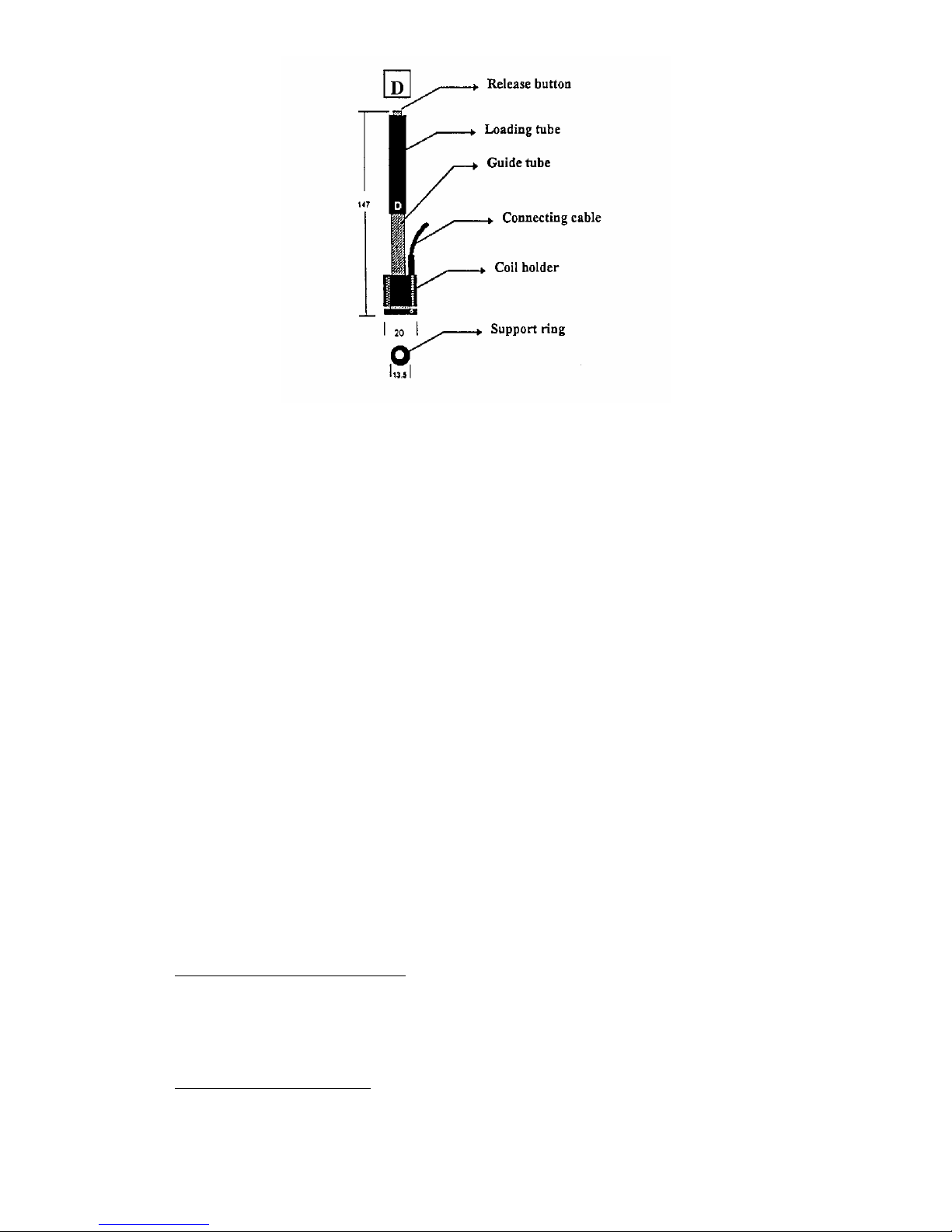
Figure 2: Type D Impact Device
2. Functions of the Phase II PHT-2500 Hardness Tester
Phase II PHT-2500 is an advanced, handheld hardness tester that provides high
accuracy and simplicity of operation for a wide measuring range. It is suitable
for testing the hardness of ordinary metals and is widely applied in many
industries including the petroleum, chemical, industrial machining and electric
power industries, etc.
2.1 Typical Applications
Typical hardness testing applications of the PHT-2500 include:
• Inspection of installed machinery, permanent parts of assembled systems and
heavy workpieces
• Inspection of the moulding surface of a die
• Analysis of pressure vessels, turbo generator sets, etc.
• Inspection of bearing and other mass produced parts on a production line
• Obtaining original records of test data
• Identification of metallic materials stored in a warehouse
2.2 Technical Data
• Display error ±0.8% at LD=900
(Value display – Value actual x 100)
Value Actual
• Relative repetitive display error 0.8% at LD=900
(Value max – Value min. x 100) = Error
Value Average
2
Page 4
2.3 Available Functions
• Automatic identification of integrated impact device (D, DC, DL, D+15, C, G)
• Quick entry of a series of test numbers, test dates, sample material type and
impact direction via the keypad.
• Deletion of erroneous or incorrect previously stored test data.
• Display of the current test mode and its corresponding test data.
• Quick print out of all test results via an optional mini-printer
• User selectable display of test data in any hardness value (
HL, HRC, HRB, HB,
HV, HSD)
•
Low Battery Indicator
2.4 Measuring and Converting Ranges
Shown in Tables 1-7 are the impact devices, the corresponding measuring ranges for
each (D, DC, DL, D+15, C, G) and their allowable conversion ranges in terms of other
static hardness values (
HRC, HRB, HB, HV, HSD
) for different metals.
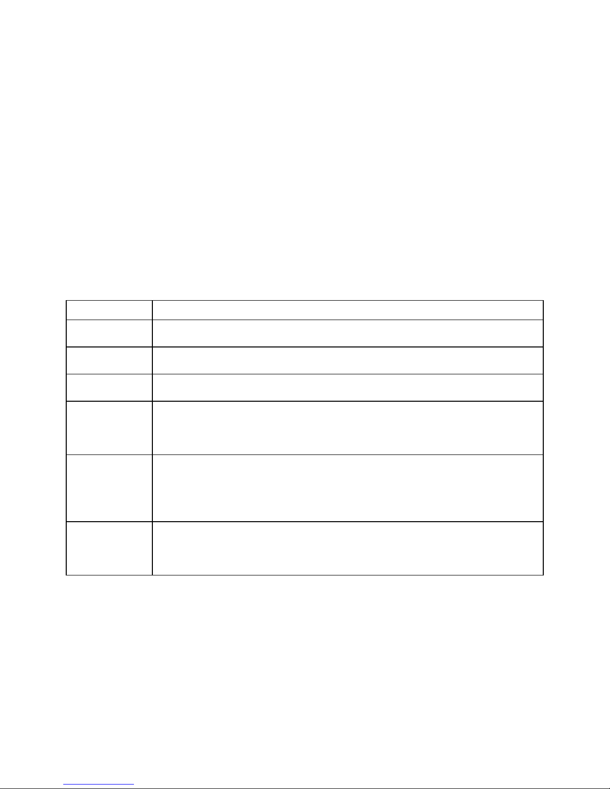
Probe Application
D
DC
D+15
C
G
DL
Universal standard unit. Will handle the majority of hardness testing
applications. Weight: 75g
Very short impact device for those confined areas, i.e. inside bores for internal
measurements. Conforms to the D measuring range.
Very narrow contact area with a set backed measurement coil. This device is
used to measure hardness in grooves and recessed surfaces.
A reduced impact energy impact device
for measuring the hardness of surface hardened components, coatings, thin
wall or impact sensitive components. Applies a small superficial indentation.
Weight
This device has an enlarged test tip, and an increased impact energy range
(approx. 9 times the D, 72 ft-lb.). Can be used on lower quality finishes for
measuring hardness in the Brinell range only (max. 650 HB). Designed to be
used with heavy components such as heavy castings and forgings.
Weight
This model features a needle front section with a diameter of 4mm and a
length of 50mm. It is suitable for testing in extremely confined spaces, the
base of grooves and of special components such as gear wheels.
For use on steel and cast steel only!
: 75g (will not function at –180 degrees)
: 250g
(approximately ¼ of the D Type 2 ft-lb.)
Weight
: 50g
Weight
: 80g
3
Page 5
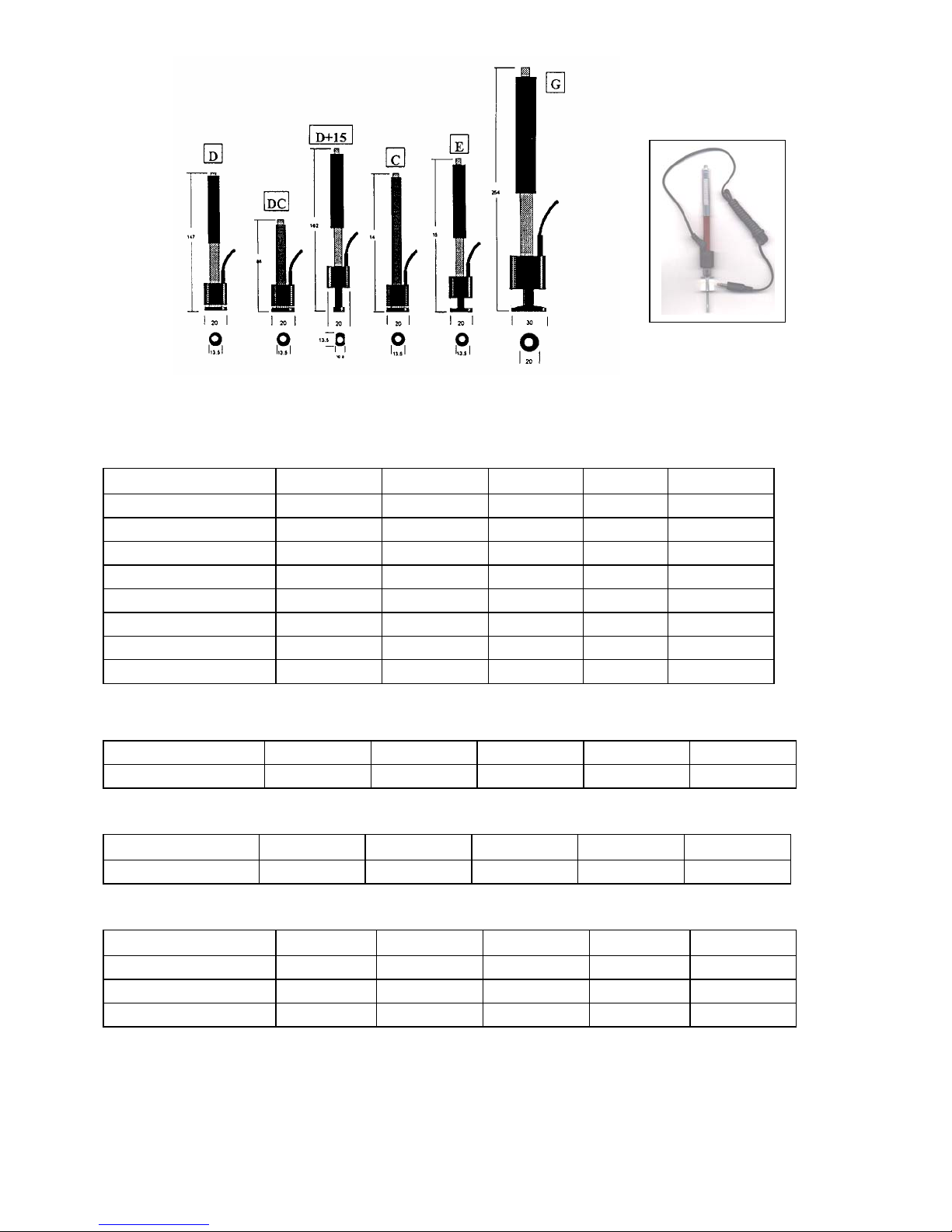
DL Impact Probe
Figure 3: Optional Impact Devices
Table 2: Impact Device – D, DC Measuring Range LD:200-900
Material HRC HRB HB HV HSD
Steel 17.9-68.5 59.6-99.5 93-651 83-976 32.2-99.5
C.W. Tool Steel 20.4-67.1 80-898
Gray Cast Iron 93-334
Nodular Cast Iron 131-387
Cast Aluminum 30-159
Brass 13.5-95.3 40-173
Bronze 60-290
Copper 45-315
Table 3: Impact Device – D+15, Measuring Range LD+15: 300-900
Material HRC HRB HB HV HSD
Steel & Cast St. 19.3-67.9 80-638 80-937 33.3-99.3
Table 4: Impact Device – C, Measuring Range LC: 350-950
Material HRC HRB HB HV HSD
Steel & Cast St. 20.0-69.5 80-683 80-996 31.9-99.6
Table 5: Impact Device – G, Measuring Range LG: 300-750
Material HRC HRB HB HV HSD
Steel & Cast St. 47.7-99.9 90-646
Gray Cast Iron 92-326
Nodular Cast Iron 127-364
4
Page 6
3. Leeb Measuring Method
3.1 History
The Leeb measuring method was first brought into measurement technology in 1978.
It is defined as the quotient of an impact body’s rebound velocity over its impact
velocity, multiplied by 1000. Harder materials produce a higher rebound velocity than
softer materials. For a specific group of material (e.g. steel, aluminum. etc.). Leeb
hardness value represents a direct relationship to its hardness properties. For ordinary
metal, conversion curves of hardness HL versus other standard static hardness (HB, HV,
HRC, etc.) are available, enabling you to convert HL into other hardness values.
3.2 Leeb Hardness Test (definition)
An impact body with a spherical test tip made of tungsten carbide is propelled against
the sample surface by a spring force and then rebounds back. At a distance of 1mm
from the sample surface, the impact and rebound velocity of the impact body are
measured by the following method: A permanent magnet embedded in the impact
body, when passing through the coil in its coil holder, induces in the coil an electric
voltage proportional to the velocities of the magnet. Leeb hardness is expressed by the
following formula:
HL = 1000 x (VB/VA)
Where: HL is Leeb Hardness
V
V
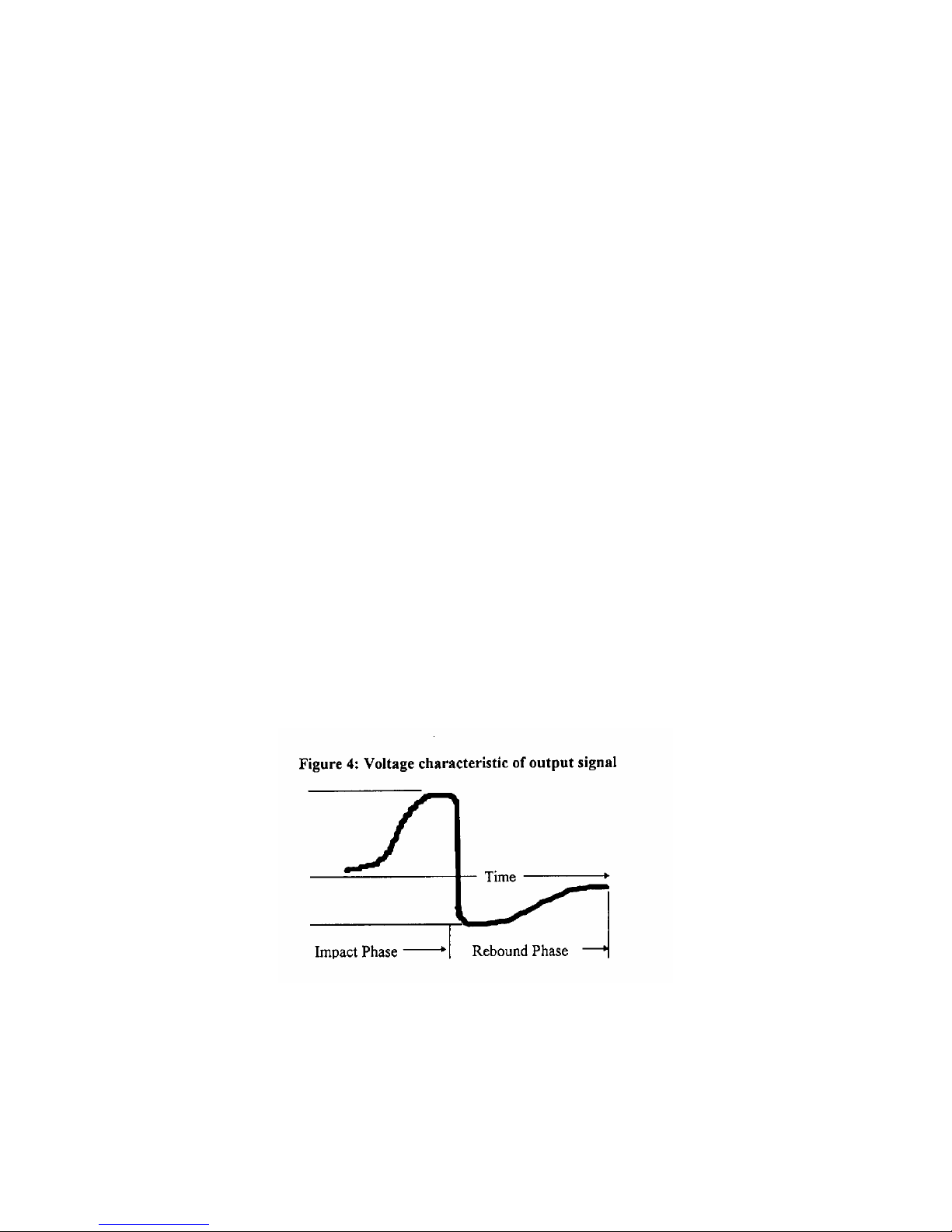
The voltage characteristic of output signal, when the impact body passes through the
induction coil is illustrated in the following figure:
is the rebound velocity of the impact body
B
is the impact velocity of the impact body
A
3.2 Leeb’s Hardness Tester (definition)
A Leeb’s Hardness Tester measures the hardness of sample material in terms of
Hardness Leeb (HL), which can be converted into other Hardness units (Rockwell B and
C, Vicker, Brinell and Shore D).
5
Page 7

3.3 Notation of Leeb’s Hardness
• When measuring the hardness of a sample material using the traditional static
hardness testing method, a change of applied pressure will result in a change in
the hardness reading. This will also happen during a Leeb’s Hardness test when
you change the impact device. In measuring the hardness of the same test
sample with different impact devices, the Leeb’s hardness values obtained will
vary.
For Example: 720 HLD≠720 HLC
• Because different converting curves are obtained from different impact devices,
when converting hardness L into another hardness value the notation for the
converted hardness value should include the impact device used.
For example:
Hardness HV converted from hardness L using impact device D+15
Should be written as 22, 8 HV LD+15
Where: 22=hardness value HL
8=hardness value HV
L=Leeb’s Method
LD+15-impact device
Hardness HRC converted from hardness L using impact device D should be
written as 35, 9 HRCLD
Where: 35=hardness value HL
9=hardness value HRC
L=Leeb’s Method
D=Impact device
4. Pretreatment of Samples
4.1 Pretreatment of Sample Surface
To eliminate hardness errors resulting from the roughness of a sample’s surface when
using impact device D, DC or D+15, the test surface should be polished until its
roughness Ra is no more then 2µm. PHASE II SRG-1000 handheld surface roughness
tester or any other suitable instrument may be used to measure the surface roughness
of the sample material. The test surface should be clean and free from oil stains.
4.2 Curved Surface
When testing a curved surface with a radius of curvature R less than 1.2 in (30mm), a
special small support ring washer should be used to compensate the curvature.
6
Page 8

4.3 Supporting a Test Sample
When using impact devices D, DC or D+15 (Impact energy=9ft/lbs), please refer to the
following support requirements:
• For test samples weighing over 11 lbs. (5 kg), no support is required.
• Samples having a cantilever or thin shell shape and weighing between 4.4 to 11
lbs. (2 to 5 kg) must be firmly coupled to bearing supports weighing over 11 lbs.
(5 kg) in order to prevent bending, deformation or displacement due to the
impact force.
• Test samples weighing less than 4.4 lbs. (2 kg) should be firmly coupled to a
support weighing over 11 lbs. (5 kg).
• The coupling surface between the sample and the support should be smooth.
• A moderate, non-excessive amount of coupling paste should be applied between
the coupling surfaces when testing thin cross section pieces with larger massed
support plates.
• The direction of impact should be perpendicular to the coupled surface.
• Minimum weight of a test sample should be 0.2 lbs. (100 g).
• Minimum thickness of a test sample should be 0.2 in (5 mm).
• Minimum depth of hardened layer should be 0.03 in (0.8 mm).
• The testing surface of the sample should be perpendicular to the impact
direction.
Note: The above restrictions referring to the rigidity of test samples can be decreased
when Type C (2ft/lbs) impact device is used as should be increased when Type G (72
ft/lbs.) is used.
4.4 Large Test Samples
When the test sample is a large plate, long bar or bent work piece, the impact force
can cause a deformation or instability when the impact device is released. This may
bring about an error in measurement, even if the weight or thickness of the test sample
seems applicable. In this case, a reinforcement should be attached to the back of the
sample surface opposite to the impact force.
4.5 Test Sample Properties
Requirements for a sample’s weight thickness and roughness differ for each impact
device, as shown in Table 8.
Table 8: Sample Requirements for Hardness Testers
Sample
Impact
Device
D, DC,
D+15
G
C
Sample Weight(kg) Min. Thickness
(mm)
Needs
Support
Needs to
be
stabilized
No
strength-
eing
needed
Sample
Hardened
layer
ISO Ra Rz
0.05-2 2.5 >5 3 0.8 N7
0.5-5 5-15 >15 10 N
0.02-
0.05
0.5-
1.5
>1.5 1 0.2 N
9
5
Max. Roughness
(or Min. Fineness)
2µ 10µ ∇6
7µ 30µ ∇4
0.4µ 2.5µ ∇8
7
Page 9
5. Keypad Functions
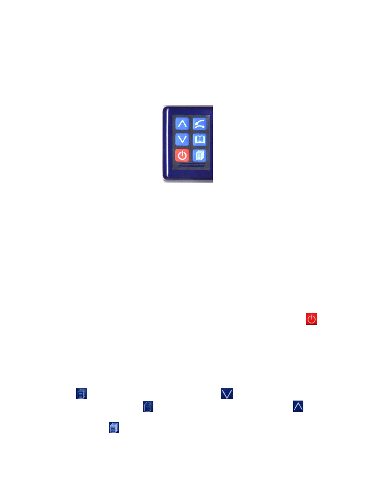
Shown in Fig 6 are the keypad function buttons.
Top left button Scroll up (Back light)
Top right button Delete last test
Middle left button Scroll down
Middle right button Memory recall
Bottom left button Power on/off
Bottom right button Menu display/Save entry button
6. Operation of the Instrument
6.1 Starting
Insert the plug of the impact device into the processor and switch on the power
The LCD will display the same settings that were previously set. If the display meets
your current testing requirements, you can start the test immediately. If not, you can
enter your required settings using the keypad.
6.2 Setting of all Parameters
•
Choosing an Impact Device
.
Press the button to go to the main menu. Use the button to scroll down to:
2. Impact Device. Press the
to scroll across to the desired impact device. When the desired device is highlighted,
you must press the
button to save entry.
button to enter this parameter. Press the button
8
Page 10
•
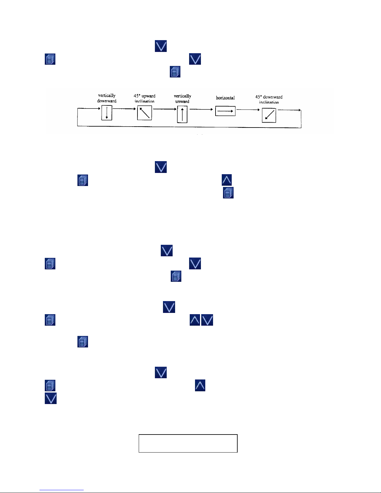
Setting your Impact Direction
While in the main menu, use the button to scroll down to: 3. Direction. Press the
button to enter this parameter. Use the button to move the cursor until you
reach the desired direction. Press the
button to save this entry.
Figure 7: Impact Direction
•
Obtaining an Average
While in the main menu, use the button to scroll down to: 4. Average Times.
Press the button to enter this parameter. Use the button to change the
test/average times from 2 times to 8 times. Press the button to save entry. This
function allows you to view the average of the amount of tests you entered.
Example
: If you chose “3”. The tester will show the average after 3 consecutive tests.
All test results will be shown on the display.
•
While in the main menu, press the button to scroll down to: 5. Material. Press the
Selecting a Material
button to enter this parameter. Use the button to scroll down the list until the
desired material is reached. Press the button to save entry.
•
Choosing a hardness Scale
While in the main menu, press the button to scroll down to: 6. Scale. Press the
button to enter this parameter. Use the buttons to scroll across the 6
choices of hardness scales. When the desired scale has been highlighted, you should
press the button to save this entry.
•
Setting Limitations
While in the main menu, use the
button to enter this parameter. Using the button to change the numbers and the
(upper & lower)
button to scroll down to: 7. Tolerance. Press the
button to change columns, you can enter your desired upper and lower limitations.
What this parameter allows the tester to do is signal you when a particular test has
fallen outside the set limitations. The LCD display will read as follows:
over range-repeat
9
Page 11
•
Entering Date & Time
While in the main menu, use the button to scroll down to: 8. Date and Time.
Press the button to enter this parameter. Use the button to change the
numerical values. Use the button to move to the next column. When your entry has
been completed, press the button to save your entry.
•
Setting Memory Locations
While in the main menu, use the button to scroll down to: 9. Location. Press the
button to enter this parameter. Use the button to change the numerical value.
Use the button to move to the next column. When your entry has been completed,
press the button to save this entry.
•
Memory Recall
While in the main test screen, press the button to recall stored data
IMPORTANT: this feature allows the user to keep track of previous measured values for future references
or printing purposes. Always keep note of your selections to quicken the process of finding your desired
measurement.
•
Error Modify
(deletions)
When an error occurs in your test grouping, you can push the button to delete the
previous test result. This will only allow one deletion per test
Example:
If you take 3 tests and the second test result is
erroneous, you can push the *button to delete that last test. You
will not be able to immediately change the first test.
Memory Function
•
While in the main menu, use the button to scroll down to: 10. Memory. Press the
to enter this parameter.
1) Auto Store:
This function will allow the user to automatically store each test result in the next available memory
location by ascending order.
2) Close store:
This function will allow the user to perform tests without any results being saved in memory. If memory
or printing functions are not needed, then this is the parameter that should be set.
When the desired memory function is set, press the
to save this entry.
10
Page 12
Printing stored Data using a PC or optional mini-printer
Optional Mini-printer:
Connect the included power supply in the back end of the printer. Using the supplied
data port connections, connect the single port end into the side of the PHT-2500.
Connect the 9-pin female end to the included dual male end adapter. Connect the 25pin adapter male end to the 25-pin female end data port of the mini-printer.
Follow instructions below.
Printing to a PC:
All instructions are the same as the mini-printer except you must connect the 25-pin
male end to the printer port of your PC. The desired program needed to run this
operation should be left to the discretion of the end user.
•
Printing stored Data
While in the main menu, press the button to scroll down to: 11: PRINT. Press the
to enter this parameter. The display will show a starting location and an end
location. Using the button, you can change the numerical value to the desired
memory location needed to print. Press the button to change columns. Using this
method. Enter the memory location of the first test result needed
(starting location
(
end location
) and then enter the memory location of the last test result
)needed to print.
Example:
If you chose memory location 0150 to start a set of 10 tests,
this would mean that you have stored your last test result in
memory location 0160. In order to print these test results, you
must enter 0150 as your start location and 0160 as your end
location.
11
Page 13
Begin Testing:
While in the main menu, use the to go to: 1. Measurement. Press the to enter
the main testing screen. Begin Testing.
6.3 Measuring Procedure
Use standard test block to check your hardness tester prior to a hardness test.
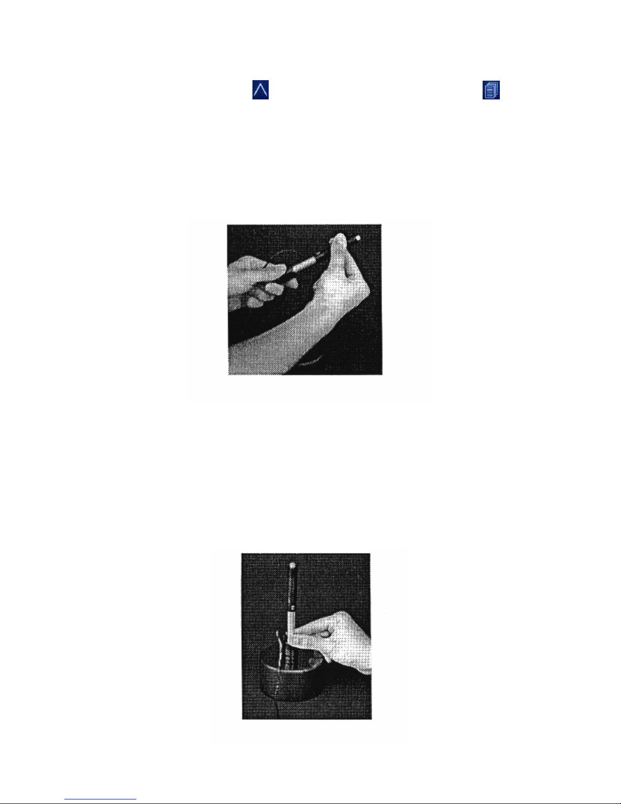
(1) Loading
Press down the loading tube to lock the impact body. (Fig 9)
Figure 9: Loading the PHT-2500
(2) Placement
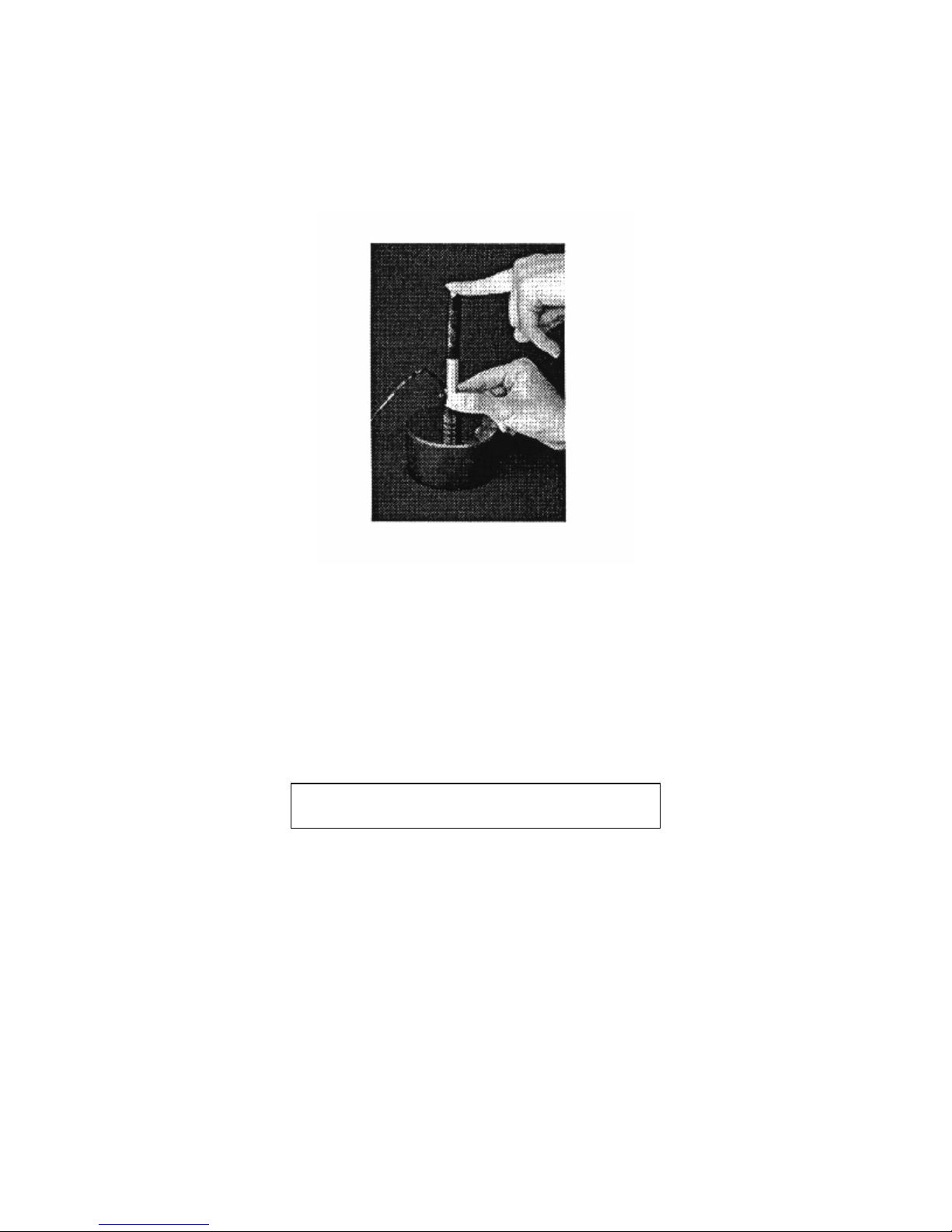
Place the support ring on the surface to be measured. The distance between two test
points should not be less than 0.1 in (3mm) (Fig 10).
Figure 10: Placement of Tester
12
Page 14
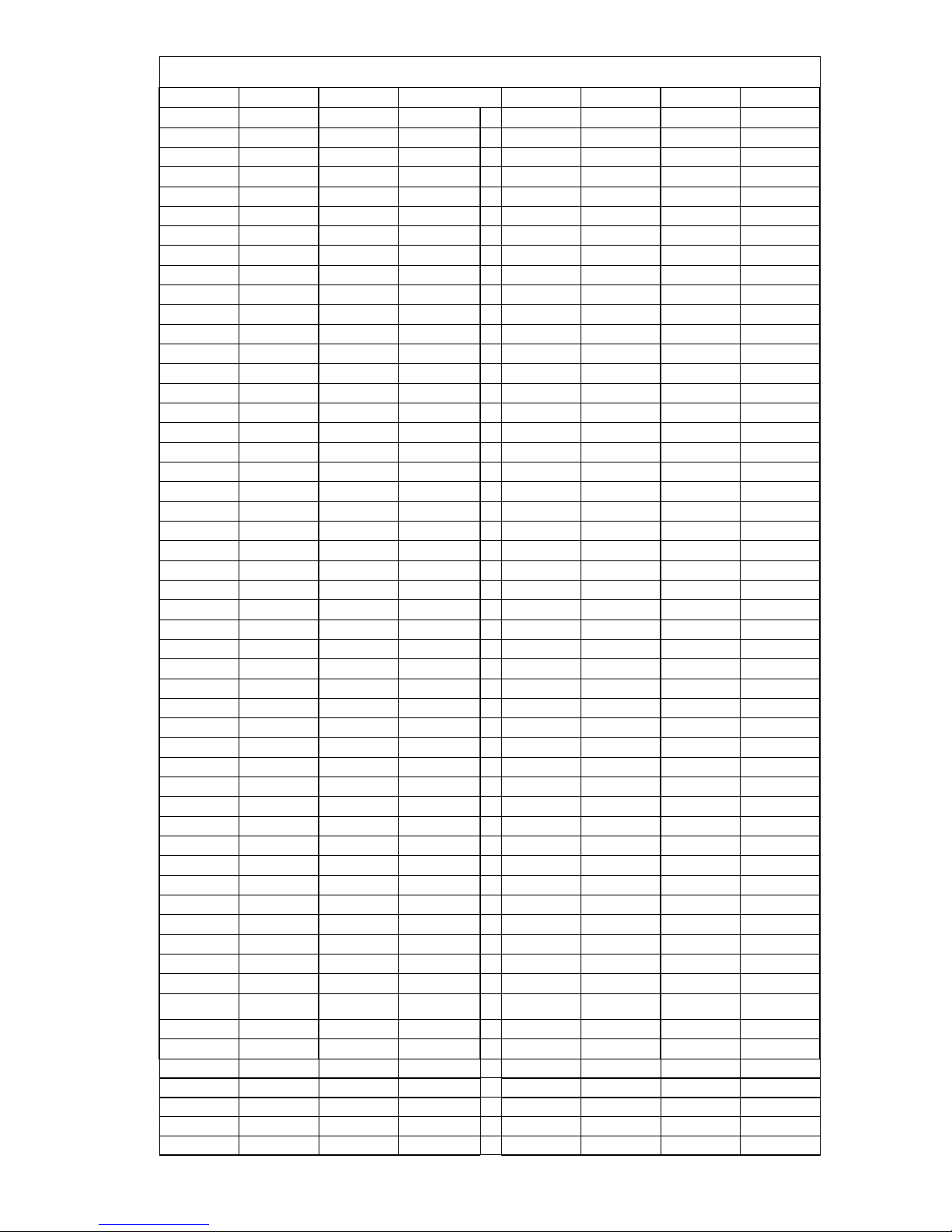
(3) Starting
Trigger the release button while the work piece, the impact device and the impact body
are all stable and the starting force coincides with the axis of the impact device (Fig.
11).
Figure 11: Starting a Measurement
When one measurement of a set is finished, the hardness value measured will be
displayed on the LCD screen and the number of measurement times will increase by
one.
If the test data lies outside of the conversion range it will be displayed as:
over range repeat
on the LCD screen and will then be nullified.
6.4 Arithmatic Mean of Hardness of Current Measurements
Usually the arithmatic mean of measurements should be the average of 5 to 33 or more
sets of measured data.
6.5 Shutting off the PHT-2500
Press the Red power button to terminate use of the PHT-2500.
13
Page 15

6.6 Additional Features
• Set time and date and serial number of the test can be modified during a
measuring procedure, as necessary.
• Alteration of parameters including hardness value and type of sample material
can be performed during any measurement set. The output results of the
measurement set will conform to the newly modified setting. All the displayed
results from the current test set will follow the newly set parameters, except for
the impact direction.
• The setting of the impact direction can be changed at any time during a testing
procedure. However, only the input data after the change will be processed
according to the new setting. Data from the set impact direction before the
change will remain unchanged.
6.7 Trouble Shooting
• If the LDC screen continuously blinks, this may suggest a low battery voltage.
Simply turn off the power and change the batteries.
7. Maintenance and Repair
Avoid placing the PHT-2500 near locations where it can be exposed to shock, heavy
dust, dampness, strong magnetic fields and oil stains.
7.1 Impact Device
• Using the included brush, clean the guide tube and impact body after it has
performed 1000-2000 tests using the following procedure:
Screw off the support ring and take out the impact body.
Clean the tube by winding the brush counter-clockwise into the tube until it
reaches the bottom and then pull it out. Repeat this procedure 5-6 times.
Replace the impact body and support ring.
Release the impact spring after each test.
Never apply lubrication of any kind to impact body!
7.2 Repair
• When the tester is calibrated against the Rockwell standard test block and issues
a reading over 1 HRC, it
and should be replaced.
• Upon coming across any functional problems not mentioned in this manual,
contact a Phase II Customer Service Representative at (201)933-6300.
•
• If the unit is opened, its warranty will automatically become void.
DO NOT open the PHT-2500 or dismount any of its fixed parts. This
precision instrument should only be serviced by a factory trained service
representative.
Thank you for choosing
as your supplier of quality measuring tools
could
mean the spherical ball of the tester is worn out
14
Page 16

Revised operational instructions for the DL impact probe
If you purchased your PHT-2500 hardness tester prior to ordering your optional DL impact probe,
you must follow the instructions below before performing any tests. Without these instructions, the
outcome of hardness values will display higher than the actual hardness value of the sample test
piece.
Due to the special shape and design of the optional DL impact probe, the outcome of hardness values will
vary when compared to that of the standard D impact probe. The hardness scale for the DL impact probe
is known as HLDL. This change is how the gage can compensate for the longer impact tube. When using
the standard D impact probe, you use the HLD scale for hardness. Typically, this is the hardness scale
shown on all supplied test blocks. The HLD value will range from 750-830 Leeb. If you had purchased the
optional DL impact probe with the gage, you should have the HLDL value already shown on the test block.
If not, you need to follow the directions below.
Equation
Example: HLD 785 = HLDL 905 (785 + 120 =905)
By following this equation, you can then calibrate the hardness tester to the supplied test block by using
you new HLDL value. Once the gage has been calibrated, you can begin testing at your convenience.
The following instructions are recommended for calibrating the PHT-2500 hardness tester.
Make sure the gage is reading correctly with the standard D probe. If the reading is within +/- 1 HRC or +/- 8HLD, you are
within acceptable tolerance. Perform a minimum of 5 consecutive tests to get an accurate average. It is always
recommended to perform between 5 and 30 consecutive tests to provide you with the closest possible average.
If you need further assistance, please contact Phase II customer service at (201)933-6300
: HLD + 120 = HLDL
2
Page 17

ASTM Hardness
Round Correction Factors
Corrections to be added to test results in the following scales for various diameter parts
Corrections to be added to Rockwell C, A, and D values
Hardness Diameter of Convex Cylindrical Surfaces
Reading 1/4 inc 3/8 in 1/2 in 5/8 in 3/4 in 7/8 in 1 in 1-1/4 in 1-1/2 in
6.4 mm 10 mm 13 mm 16 mm 19 mm 22 mm 25 mm 32 mm 38 mm
20 6.0 4.5 3.5 2.5 2.0 1.5 1.5 1.0 1.0
25 5.5 4.0 3.0 2.5 2.0 1.5 1.0 1.0 1.0
30 5.0 3.5 2.5 2.0 1.5 1.5 1.0 1.0 0.5
35 4.0 3.0 2.0 1.5 1.5 1.0 1.0 0.5 0.5
40 3.5 2.5 2.0 1.5 1.0 1.0 1.0 0.5 0.5
45 3.0 2.0 1.5 1.0 1.0 1.0 0.5 0.5 0.5
50 2.5 2.0 1.5 1.0 1.0 0.5 0.5 0.5 0.5
55 2.0 1.5 1.0 1.0 0.5 0.5 0.5 0.5 0
60 1.5 1.0 1.0 0.5 0.5 0.5 0.5 0 0
65 1.5 1.0 1.0 0.5 0.5 0.5 0.5 0 0
70 1.0 1.0 0.5 0.5 0.5 0.5 0.5 0 0
75 1.0 0.5 0.5 0.5 0.5 0.5 0 0 0
80 0.5 0.5 0.5 0.5 0.5 0 0 0 0
85 0.5 0.5 0.5 0 0 0 0 0 0
90 0.5 0 0 0 0 0 0 0 0
Corrections to be added to Rockwell B, F, and G values
Hardness Diameters of Convex Cylindrical Surfaces
Reading 1/4 in 3/8 in 1/2 in 5/8 in 3/4 in 7/8 in 1 in
6.4 mm 10mm 13mm 16 mm 19 mm 22 mm 25 mm
0 12.5 8.5 6.5 5.5 4.5 3.5 3.0
10 12.0 8.0 6.0 5.0 4.0 3.5 3.0
20 11.0 7.5 5.5 4.5 4.0 3.5 3.0
30 10.0 6.5 5.0 4.5 3.5 3.0 2.5
40 9.0 6.0 4.5 4.0 3.0 2.5 2.5
50 8.0 5.5 4.0 3.5 3.0 2.5 2.0
60 7.0 5.0 3.5 3.0 2.5 2.0 2.0
70 6.0 4.0 3.0 2.5 2.0 2.0 1.5
80 5.0 3.5 2.5 2.0 1.5 1.5 1.5
90 4.0 3.0 2.0 1.5 1.5 1.5 1.0
100 3.5 2.5 1.5 1.5 1.0 1.0 0.5
When testing cylindrical specimens, the accuracy of the test will be seriously affected by alignment of elevating screw, Veeanvil, indenters, surface finish, and the straightness of the cylinder. These corrections are approximate only and represent the
averages, to the nearest 0.5. Rockwell and Rockwell superficial numbers, of numerous actual observations.
The above tables are from ASTM E 18
Reprinted from the Annual Book of STM Standards, copyright American Society for Testing and Materials.
100 Harbor Drive, West Conshohocken , PA 19428-2959
3
Page 18

ASTM Hardness Conversion Chart
Rockwell C Hardness Range
Approximate Hardness Conversion Numbers for Non-Austenitic Steels, According to ASTM E-140
The Conversion Values contained herein should be considered approximate only and may be inaccurate for specific
applications
C A D 15N 30N 45N Vickers Knoop Brinell Tensile
150 kgt 60 kgt 100kgt 15kgt 30 kgt 45 kgt Hardness Hardness Hardness Strenght
diamond diamond diamond diamond diamond diamond 500gr 3000kgt 1000 lbs/
and over 10mm ball square in
68 85.6 76.9 93.2 84.4 75.4 940 920 .. ..
67 85.0 76.1 92.9 83.6 74.2 900 895 .. ..
66 84.5 75.4 92.5 82.8 73.3 865 870 .. ..
65 83.9 74.5 92.2 81.9 72.0 832 846 (739)
64 83.4 73.8 91.8 81.1 71.0 800 822 (722)
63 82.8 73.0 91.4 80.1 69.9 772 799 (705)
62 82.3 72.2 91.1 79.3 68.8 745 776 (688)
61 81.8 71.5 90.7 78.4 67.7 720 754 (670)
60 81.2 70.7 90.2 77.5 66.6 697 732 (654)
59 80.7 69.9 89.8 76.6 65.5 674 710 (634) 351
58 80.1 69.2 89.3 75.7 64.3 653 690 615 338
57 79.6 68.5 88.9 74.8 63.2 633 670 595 325
56 79.0 67.7 88.3 73.9 62.0 613 650 577 313
55 78.5 66.9 87.9 73.0 60.9 595 630 560 301
54 78.0 66.1 87.4 72.0 59.8 577 612 543 292
53 77.4 65.4 86.9 71.2 58.6 560 594 525 283
52 76.8 64.6 84.4 70.2 57.4 544 576 512 273
51 76.3 63.8 85.9 69.4 56.1 528 558 496 264
50 75.9 63.1 85.5 68.5 55.0 513 542 481 255
49 75.2 62.1 85.0 67.6 53.8 498 526 469 246
48 74.7 61.4 84.6 66.7 52.5 484 510 455 237
47 74.1 60.8 83.9 65.8 51.4 471 495 443 229
46 73.6 60 83.5 64.8 50.3 458 480 432 221
45 73.1 59.2 83.0 64.0 49.0 446 466 421 215
44 72.5 58.5 82.5 63.1 47.8 434 452 409 208
43 72.0 57.7 82.0 62.2 46.7 423 438 400 201
42 71.5 56.9 81.5 61.3 45.5 412 426 390 195
41 70.9 56.2 80.9 60.4 44.3 402 414 381 188
40 70.4 55.4 80.4 59.5 43.1 392 402 371 182
39 69.9 54.6 79.9 58.6 41.9 382 391 362 177
38 69.4 53.8 79.4 57.7 40.8 372 380 353 171
37 58.9 53.1 78.8 56.8 39.6 363 370 344 166
36 68.4 52.3 78.3 55.9 38.4 354 360 336 161
35 67.9 51.5 77.7 55.0 37.2 345 351 327 156
34 67.4 50.8 77.2 54.2 36.1 336 342 319 152
33 66.8 50.0 76.6 53.3 34.9 327 334 311 149
32 66.3 49.2 76.1 52.1 33.7 318 326 301 146
31 65.8 48.4 75.6 51.3 32.5 310 318 294 141
30 65.3 47.7 75.0 50.4 31.3 302 311 286 138
29 64.8 47.0 74.5 49.5 30.1 294 304 279 135
28 64.3 46.1 73.9 48.6 28.9 286 297 271 131
27 63.8 45.2 73.3 47.7 27.8 279 290 264 128
26 63.3 44.6 72.8 46.8 26.7 272 284 258 125
25 62.8 43.8 72.2 45.9 25.5 266 278 253 123
24 62.4 43.1 71.6 45.0 24.3 260 272 247 119
23 62.0 42.1 71.0 44.0 23.1 254 266 243 117
22 61.5 41.6 70.5 43.2 22.0 248 261 237 115
21 61.0 40.9 69.9 42.3 20.7 243 256 231 112
20 60.5 40.1 69.4 41.5 19.6 238 251 226 110
Hardness values in Brackets are outside the range recommended for Brinell testing in ASTM E-10.
The above tables is from ASTM E-110 except values for E-scale and Tensile Strength which are not from or according to
ASTM Standards.
Reprinted from the Annual Book of ASTM Standards,
Copyright American Society for Testing and Materials, 100 Barr Harbor Drive,West Conshohocken,PA 19428-2959.
4
Page 19

ASTM Hardness Conversion Chart
Rockwell B Hardness Range
Approximate Hardness Conversion Numbers for Non-Austenitic Steels, according to ASTM E-140
The conversion values contained herein should be considered approximate only and may be inaccurate for
Specific applications.
Rockwell Superficial Rockwell Vickers Knoop Brinell Tensile Brinelll
B A E 15T 30T 45T Hardness Hardness Hardness Strength Hardness
100kgf 60 kgf 100 kgf 15 kgf 30 kgf 45 kg f 500gf 3000 kgf 1000 lbs/ 500 kgf
1/16"ball diamond 1/8" ball 1/16" ball 1/16"ball 1/16" ball and over 10mm ball square in 10mm ball
100 61.5 93.1 83.1 72.9 240 261 240 116 201
99 60.9 82.8 82.5 71.9 234 246 234 114 195
98 602 92.5 81.8 709 228 241 228 109 189
97 59.5 92.1 81.1 699 222 236 222 105 184
96 58.9 91.8 80.4 689 216 231 216 102 179
95 58.3 91.5 79.8 67.9 210 226 210 100 175
94 57.6 91.2 79.1 669 205 221 205 98 171
93 57 90.8 784 659 200 216 200 94 167
92 56.4 90.5 77.8 64.8 195 211 195 92 163
91 55.8 90.2 77.1 63.8 190 206 190 90 160
90 55.2 89.9 76.4 62.8 186 201 186 89 157
89 54.6 89.5 76.8 61.8 180 196 180 88 164
88 64.0 89.2 75.1 60.8 176 192 176 86 151
87 53.4 88.9 74.4 59.8 172 188 172 84 148
86 52.8 88.6 73.8 58.8 169 184 169 83 145
85 52.3 88.2 73.1 57.8 165 180 165 82 142
84 51.7 87.9 72.4 56.8 162 176 162 81 140
83 51.1 87.6 71.8 55.8 159 173 159 80 137
82 50.6 87.3 71.1 54.8 156 170 156 76 135
81 50 86.9 70.4 53.8 153 167 153 73 133
80 49.5 86.6 69.7 52.8 150 164 150 72 130
79 48.9 86.3 69.1 51.8 147 161 147 70 128
78 48.4 86.0 68.4 50.8 144 158 144 69 126
77 47.9 85.6 67.7 49.8 141 155 141 68 124
76 47.3 85.3 67.1 48.8 139 152 139 67 122
75 46.8 86.0 66.4 47.8 137 150 137 66 120
74 46.3 84.7 65.7 46.8 135 147 135 66 118
73 45.8 84.3 65.1 45.8 132 145 132 64 116
72 45.3 84.0 64.4 44.8 130 143 130 63 114
71 44.8 100 83.7 63.7 43.8 127 141 127 62 112
70 44.3 99.5 83.4 63.1 42.8 125 139 125 61 110
69 43.8 99.0 83.0 62.4 41.8 123 137 123 60 109
68 43.3 98.0 82.7 61.7 40.8 121 135 121 59 108
67 42.8 97.5 82.4 61 39.8 119 133 119 58 106
66 42.3 97.0 82.1 60.4 38.7 117 131 117 57 104
65 41.8 96.0 81.8 59.7 37.7 116 129 116 56 102
64 41.4 95.5 81.4 59 36.7 114 127 114 100
63 40.9 95.0 81.1 58.4 35.7 112 125 112 99
62 40.4 94.5 80.8 57.7 34.7 110 124 110 98
61 40.0 93.5 80.5 57.0 33.7 108 122 108 96
60 39.5 93.0 80.1 56.4 32.7 107 120 107 95
59 39.0 92.5 79.8 55.7 31.7 106 118 106 94
58 38.6 92.0 79.5 55 30.7 104 117 104 92
57 38.1 91.0 79.2 54.4 2.97 103 115 103 91
56 37.7 90.6 78.8 53.7 28.7 101 114 101 90
55 37.2 90.0 78.6 53.0 27.7 100 112 100 89
54 36.8 89.5 78.2 52.4 26.7 111 87
53 36.3 89.0 77.9 51.7 26.7 110 86
52 35.9 88.0 77.5 51.0 24.7 109 85
51 35.5 87.6 77.2 50.3 23.7 108 84
50 35.0 87.0 76.9 49.7 22.7 107 83
49 34.6 86.5 76.6 49.0 21.7 106 82
5
Page 20

48 34.1 85.5 76.2 48.3 20.7 105 81
47 33.7 85 75.9 47.7 19.7 104 80
46 33.3 84.6 76.6 47.0 18.7 103 80
45 32.9 84 76.3 46.3 17.7 102 79
44 32.4 83.5 74.9 45.7 16.7 101 78
43 32.0 82.5 74.6 45.0 15.7 100 77
42 31.6 82 74.3 44.3 14.7 99 76
41 31.2 81.5 74.0 43.7 13.6 98 75
40 30.7 81 73.6 43.0 12.6 97 75
39 30.3 80 73.3 42.3 11.6 96 74
38 29.9 79.5 73.0 41.6 10.6 95 73
37 29.5 79 72.7 41.0 9.6 94 72
36 29.1 78.5 72.3 40.3 8.6 93 72
35 28.7 78.0 72.0 39.6 7.6 92 71
34 28.2 77.0 71.7 39.0 6.6 91 70
33 27.8 76.6 71.4 38.3 5.6 90 69
32 27.4 76.0 71.0 37.6 4.6 89 69
31 27.0 75.5 70.7 37.0 3.6 88 68
30 26.6 75.0 70.4 36.3 2.6 87 67
Hardness values in brackets are outside the range recommended for Brinell testing in ASTM E-10.
The above table is from ASTM E-110 except values for E-scale and Tensile Strength which are not from or according to ASTM
Standards.
Reprinted from the Annual Book of ASTM Standards, copyright American Society for Testing and Materials.
100 Barr Harbor Drive, West Conshohocken, PA 19428-2959
6
Page 21

ASTM Hardness
Minimum Thickness Requirements
Minimum allowable thickness for a corresponding hardness in the respective scales
Minimum Minimum - Rockwell - - - Superficial Rockwell - thickness thickness C A B 15N 30N 45N 15T 30T 45T
in. mm
0.006 0.15 92
0.008 0.20 90
0.010 0.25 88 91
0.012 0.30 83 82 77 86
0.014 0.36 76 78.5 74 81 80
0.016 0.41 86 68 74 72 75 72 71
0.018 0.46 84 66 68 68 64 62
0.020 0.51 82 57 63 55 53
0.022 0.56 69 79 47 58 45 43
0.024 0.61 67 76 94 51 34 31
0.026 0.66 65 71 87 37 18
0.028 0.71 62 67 80 20 4
0.030 0.76 57 60 71
0.032 0.81 52 62
0.034 0.86 45 52
0.036 0.91 37 40
0.038 0.96 28 28
0.040 1.02 20
The above tables are from ASTM E 18.
Reprinted from the Annual Book of ASTM Standards, copyright American Society for Testing and Materials.
100 Barr Harbor Drive, West Conshohocken, PA 19428-2959
Phase II
283 Veterans Blvd
Carlstadt, NJ. 07072
(201)933-6300
www.phase2plus.com
7
Page 22
LEEB - BRINELL CONVERSION CHART
LEEB BRINELL LEEB BRINELL LEEB BRINELL LEEB BRINELL
300 81 550 269 400 137 650 389
302 82 552 271 402 139 652 391
304 83 554 273 404 140 654 394
306 83 556 275 406 142 656 397
308 84 558 277 408 143 658 400
310 85 560 280 410 144 660 402
312 86 562 282 412 146 662 405
314 87 564 284 414 147 664 408
316 88 566 286 416 149 666 411
318 89 568 288 418 150 668 414
320 90 570 291 420 152 670 417
322 91 572 293 422 153 672 420
324 92 574 295 424 155 674 423
326 92 576 297 426 157 676 426
328 93 578 299 428 158 678 429
330 94 580 302 430 160 680 432
332 95 582 301 432 161 682 435
334 97 584 306 434 163 684 438
336 98 586 309 436 164 686 441
338 99 588 311 438 166 688 444
340 100 590 313 440 168 690 447
342 101 592 315 442 169 692 450
344 102 594 318 444 171 694 453
346 103 596 320 446 172 696 456
348 104 598 322 448 174 698 459
350 105 600 325 450 176 700 462
352 106 700 462 452 177 800 688
354 108 702 466 454 179 802 693
356 109 704 469 456 181 804 698
358 110 706 172 458 182 806 703
360 111 708 475 460 184 808 708
362 112 710 479 462 186 810 714
364 113 712 482 464 187 812 719
366 115 714 485 466 189 814 724
368 116 716 489 468 191 816 729
370 117 718 492 470 193 818 734
372 118 720 496 472 194 820 740
374 120 722 499 474 196 822 745
376 121 724 502 476 198 824 751
378 122 726 506 478 200 826 756
380 124 728 509 480 201 828 761
382 125 730 513 482 203 830 767
384 126 732 517 484 205 832 773
386 128 734 520 486 207 834 778
388 129 736 524 488 209 836 784
390 130 738 527 490 210 838 790
392 132 740 531 492 212 840 795
394 133 742 535 494 214 842 801
396 134 744 538 496 216 844 807
398 136 746 542 498 218 846 813
400 137 748 546 500 220 848 819
500 220 750 550 600 325 850 825
502 221 752 553 602 327 852 831
8
Page 23
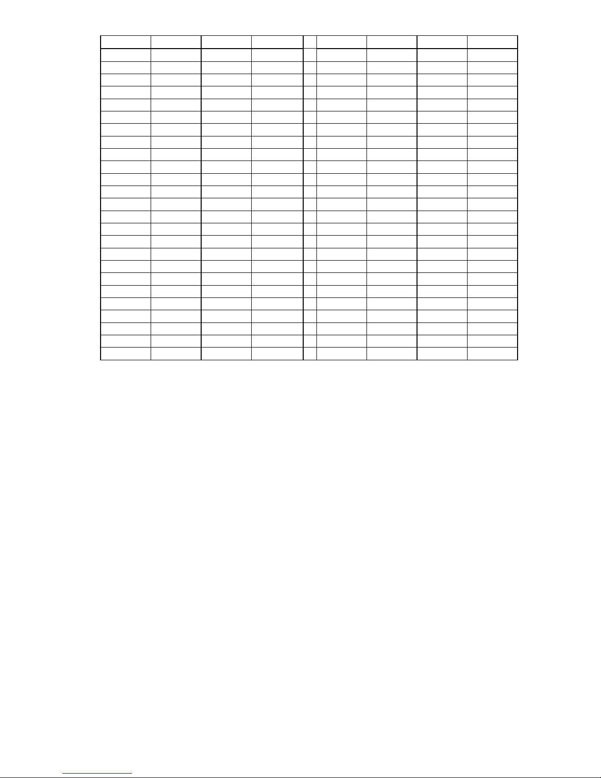
LEEB BRINELL LEEB BRINELL LEEB BRINELL LEEB BRINELL
504 223 754 557 604 330 854 837
506 225 756 561 606 332 856 843
508 227 758 565 608 334 858 849
510 229 760 569 610 337 860 855
512 231 762 573 612 339 862 862
514 233 764 577 614 342 864 868
516 235 766 581 616 344 866 874
518 237 768 585 618 347 868 881
520 239 770 589 620 349 870 887
522 241 772 593 622 352 872 894
524 243 774 597 624 354 874 900
526 245 776 601 626 357 876 907
528 247 778 606 628 359 878 914
230 249 780 610 630 362 880 920
532 251 782 614 932 365 882 927
534 253 784 618 634 367 884 934
536 255 786 623 636 370 886 941
538 257 788 627 638 372 888 948
540 259 790 631 640 375 890 955
542 261 792 636 642 378 892
544 263 794 640 644 380 894
546 265 796 645 646 383 896
548 267 798 649 648 386 898
800 654
9
 Loading...