

Page 1

Digital Vibration Tester
Model No. DVM-1000
Operation Manual
Phase II Machine & Tool, Inc.
283 Veterans Blvd
Carlstadt, NJ. 07072
(201) 933-6300
www.phase2plus.com
Find Quality Products Online at: [email protected]
www.GlobalTestSupply.com
Page 2
Features:
The DVM-1000 is a compact and simple to operate vibration tester. It’s an ideal tool for
obtaining balance and alignment data for all types of rotating objects such as heavy-duty
machinery or any fixture that uses a motor as a source of power.
The high temperature piezoelectric sensor has a removable mounting base for attachment of a
supplied stinger probe. It also is equipped with AC output socket for easy headphone hook up.
The DVM-1000 has a large 18mm LCD that will display the data in four (4) measurement modes;
Acceleration, Velocity(RMS), Displacement and RPM. Auto shut-off will conserve batteries and
will still save all previous stored data.
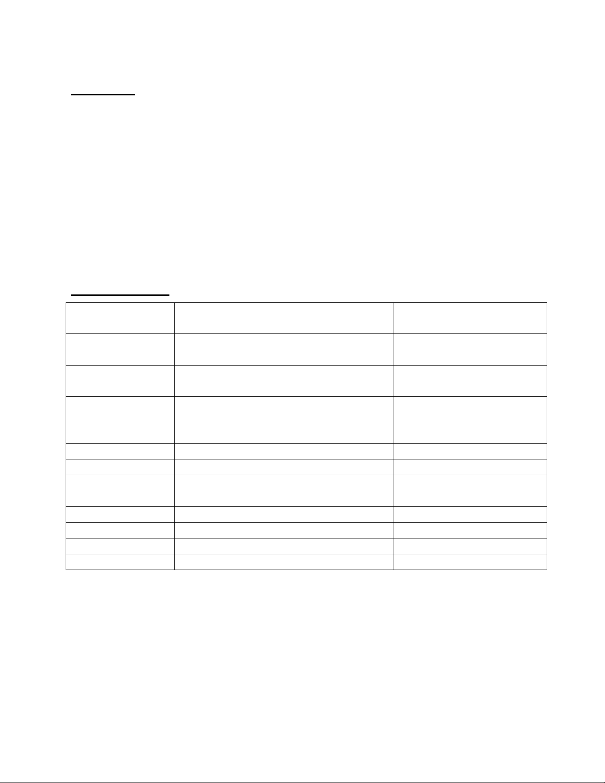
Specifications:
Acceleration
Velocity(RMS)
Displacement
RPM (revolution) 60-999,990 r/min
Frequency
Accuracy
Operating
Temperature/Humidity
Operating Output
Power Supply
Dimensions
Weight
Peak Value: 0.1 – 200 m/s
or 0.3-656 ft/m/s
RMS: 0.01-400 (mm/s)
or 0.004 -16.0 inch/s
Peak to Peak 0.001 – 4.00(mm)
or 0.04-160mil
(readings should be multiplied by 10 if the display
is set for “10”
1 – 20KHz
+/-5% +2 digits
0-50°C / below 90%RH
AC output 2.0V peak full scale
4-AAA Batteries
124 x 62 x 30mm (4.9 x 2.4 x 1.2:)
120g (not including batteries)
The DVM-1000 Kit includes:
1pc Powerful Earth Magnet
1pc Accelerometer
1pc Stinger Probe (Cone)
1pc Stinger Probe (Ball)
Operation Manual & Carry Case
Frequency Range: 10Hz-1KHz
Frequency Range: 10Hz-10KHz
Frequency Range: 10Hz-1KHz
Frequency Range: 10Hz-500Hz
Load resistance: above 10k
Find Quality Products Online at: [email protected]
www.GlobalTestSupply.com
Page 3
3-3
3-10
3-12
3-1 3-2
3-6
3-7
3-4
3-5
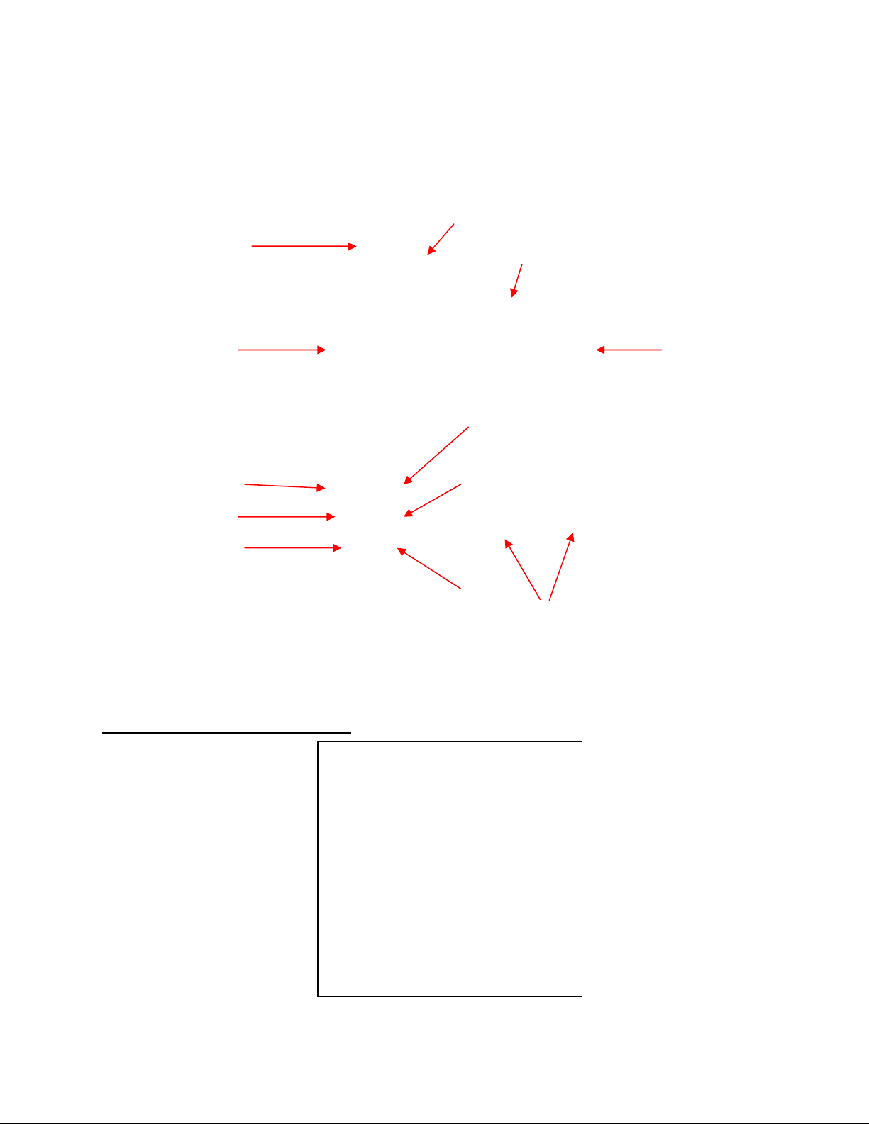
Front Panel Descriptions:
3.1 Accelerometer (Probe)
3.2 LCD
3.3 Probe Connector
3.4 Hold Key
3.5 Power Key
3.6 Inch/Metric Conversion
3.7 Function Key
3.8 Filter Key
3.9 Volume Key
3.11 Stinger Probes
3.12 Magnetic adapter
3-8
3-9
3-11
Find Quality Products Online at: [email protected]
www.GlobalTestSupply.com
Page 4

Set Up Procedure:
1. Connect the accelerometer to the input connector on the right side of the unit by
threading the socket gently until it locks in place.
2. Press the Power Button to turn unit on.
3. Place the accelerometer, with the magnetic base firmly attached to the machine. You
should allow a few seconds for the readings to stabilize before taking a reading. Machine
vibration may vary with time, in which case the maximum and minimum readings may
be recorded. The machine surface must be sufficiently flat to permit the magnetic base to
solidly attach to it. If the magnetic base is not attached properly, you will not be able to
obtain accurate readings at higher frequencies. If the measurement surface is not
magnetic or if the space is limited, the “Stinger” probes can be used in place of the
magnetic base. When using the Stinger probe hold the tip against the machine with just
enough force to prevent chattering. The stinger must be positioned perpendicular to the
desired measurement surface.
A steel disc or washer may be cemented to a non-magnetic surface to permit usage of the
magnetic base. For Maximum accuracy of Acceleration (g) measurements, the
accelerometer should be temporarily mounted on the machine surface with the supplied
(M5) threaded mounting stud.
Measurements made in more than one vibration mode can reveal something of the nature
of the vibration signal. A high acceleration reading combined with a low displacement
reading is indicative of a high frequency vibration. Conversely, a low acceleration
reading combined with a high displacement reading is indicative of a low frequency
vibration. Velocity is usually the preferred measurement when a single reading is to be
recorded. Consult the machines operation manual or the manufacturer if you are in doubt
of the measurements to be made.
The supplied vibration chart should be used as a guideline for determining machine
condition. The best indicator of machine condition is a carefully collected and recorded
history database. Changes in machine condition over time become readily apparent and
permit repairs to be made prior to machine failure.
Find Quality Products Online at: [email protected]
www.GlobalTestSupply.com
Page 5

4. Press the Function button to toggle through the 3 main measurement parameters; as well
as RPM and Frequency readings. The three main measurement scales are typically used
for vibration testing.
a) Acceleration: Normally measured in m/s2 has excellent high frequency capabilities
and is therefore very effective in determining faults in bearings or gear drives.
b) Vel oc it y: The most commonly used vibration parameter. It’s used for vibration
severity measurements in accordance with ISO 2372 which contains guidelines for
acceptable vibration levels of machinery under different power categories. These
guidelines are presented in a table in the back of this manual. Velocity is typically
measured in cm/s or Inch/s RMS (centimeters or millimeters per second). Note: this
instrument measures in cm/s. If you are more familiar with measurements in mm/s
or need to compare your measured values directly with the vibration severity chart in
this manual, you must multiply the value by 10.
c) Displacement: This parameter is typically used on low speed machines because of
it’s good low frequency response. This is NOT recommended for monitoring bearings.
Units are measured in Mil or mm equivalent peak-peak.
Calibration:
The DVM does not need a scheduled (daily, weekly, monthly) calibration performed however,
the calibration should be verified yearly by Phase II or a qualified calibration facility.
Battery Replacement:
When the battery symbol appears on the display, its time to replace the batteries.
Slide the back cover off and remove and properly dispose of the old batteries. Replace with fresh
set of batteries paying careful attention to the polarity.
Maintenance:
Be sure to keep this unit free of dirt, dust, liquids or viscous fluids. Its also best to store this unit
in a temperature controlled environment when not in use for a long period of time.
If the DVM-1000 malfunctions, contact Phase II tech support directly for instructions. Any
attempt at internal repair will void any stated or implied warranties.
Find Quality Products Online at: [email protected]
www.GlobalTestSupply.com
Page 6

Vibration Charts:
ISO 10816
This recommendation, release in August 2000, establishes the general conditions and procedures
for the measurement and evaluation of vibrations using measurements made on the non-rotating
parts of a machine. It also provides general evaluation criteria related to both operational
monitoring and acceptance testing established primarily with regard to securing reliable long
term operation of the machine.
ISO 10816-3 separates the working conditions into four zones:
• Zone A (Green): Vibration values from machines just put into operation
• Zone B (Yellow): Continuous operation without any restrictions
• Zone C (Orange): Condition is acceptable only for a limited period of time
• Zone D (Red) Dangerous vibration values-Damage could occur at any time.
It also defines four groups of machines, according to their size, base and purpose.
Find Quality Products Online at: [email protected]
www.GlobalTestSupply.com
Page 7
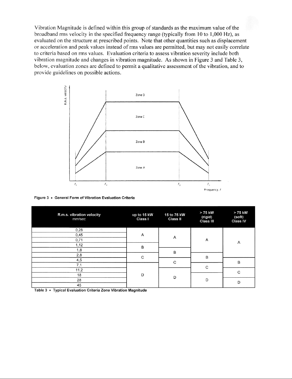
Ranking:
A=Vibration values from machines just put into operation
B= Continuous operation without any restrictions
C = Condition is acceptable only for a limited period of time
D = Dangerous vibration values-Damage could occur at any time
Find Quality Products Online at: [email protected]
www.GlobalTestSupply.com
Page 8
NEMA MG1-12.05
(Maximum vibration of motor that generates more than 1 horsepower)
RPM (Rev) Displacement (p-p) (µm)
3000-4000 25.4
1500-2999 38.1
1000-1499 50.8
<999 63.6
NEMA MG1-20.52
(Maximum vibration of high power induction motor)
RPM (Rev) Displacement (p-p) (µm)
>3000 25.4
1500-2999 50.8
1000-1499 63.6
<999 76.2
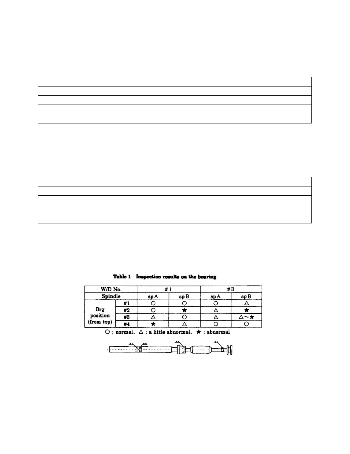
Example of Analysis chart: it’s highly suggested that you design your own chart based upon
your testing procedure and application.
Find Quality Products Online at: [email protected]
www.GlobalTestSupply.com
 Loading...