


Check out our website for more information on this and other exciting Phase3 Models products!
WWW.PHASE3MODELS.COM
ASSEMBLY INSTRUCTIONS
FIDGET 3D EP BIPLANE SPECIFICATIONS:
●
Wing Span: 31.5 Inches (800mm)
●
Wing Area: 400 Square Inches (25.8dm2)
●
Length: 31.25 Inches (794mm)
●
Weight RTF: 11.5 - 14.5 Ounces (326 - 411gr)
Phase3 Models
P.O. Box No. 74282
Kowloon Central, Hong Kong
China
All contents copyright © 2005, Phase3 Models
Version 1 January 2006
CUSTOMER SERVICE INFORMATION
●
Wing Loading: 4.15 - 5.25 Ounces/Square Foot (12.6 - 15.9gr/dm2)
●
Functions: Ailerons, Elevator, Rudder and Throttle
●
Motor & Battery Required: Xtra 2826/12, KMS 31/21 or Similar
Brushless Outrunner & 2 Cell 1350 LiPO
●
Radio Required: 4 Channel or More w/3 Micro Servos & Micro Rx
●
ESC Required: 16Amp Brushless or Suitable for Your Motor
PLEASE REFER TO THE BACK COVER OF THESE ASSEMBLY INSTRUCTIONS FOR CUSTOMER SERVICE INFORMATION
1
Kit Product Number PH107045

TABLE OF CONTENTS
Safety Warning ...................................................................................... 2
Introduction ............................................................................................ 2
Customer Service Information ..............................................................3
Section 1: Our Recommendations ....................................................... 3
Section 2: A Warning About Working with Foam.................................3
Section 3: Lithium Polymer Battery Warnings - Please Read ............ 4
Section 4: Tools and Supplies Required ............................................. 5
Section 5: Kit Contents ........................................................................ 5
Section 6: Motor and Cowling Installation ...........................................6
Section 7: Rudder Hinging and Decal Installation .............................. 7
Section 9: Bottom and Top Wing Assembly .................................... 10
Section 10: Wing Mounting ................................................................12
Section 11: Control Systems Installation ........................................... 14
Section 12: Canopy Installation .........................................................17
Section 13: ESC, Receiver and Battery Installation ..........................19
Section 14: Landing Gear Installation ............................................... 20
Section 15: Balance Point, Control Throws and Setup Information .....22
Section 16: Preflight Check and Safety ............................................. 22
Section 17: Replacement Parts List .................................................. 23
Customer Service Information .............................................Back Cover
Section 8: Stabilizer Installation...........................................................8
SAFETY WARNING
This R/C airplane is not a toy! If misused or abused, it can cause serious bodily injury and/or damage to property. Fly only in open
areas and preferably at a dedicated R/C flying site. We suggest having a qualified instructor carefully inspect your airplane before
its first flight. Please carefully read and follow all instructions included with this airplane, your radio control system and any other
components purchased separately.
INTRODUCTION
Thank you for purchasing the Phase3 Models Fidget 3D EP Biplane. We're confident that the quality of your new airplane
meets and even exceeds your expectations. Before completing the final assembly of your new airplane, please carefully
read through this instruction manual in its entirety. Doing so will ensure your success the first time around!
FEATURES:
●
Factory-Cut and Printed Foam Parts
●
Full-Shape Fuselage with Foam and Light-Plywood Stiffeners. No Tail Flexing Problems
●
Carbon Fiber Pushrods and Carbon Fiber Stiffeners for Great Strength
●
Designed for Outrunner Brushless Motors and Micro Radio Equipment
●
Different Color Scheme on Top and Bottom Presents Well During Maneuvers
●
Includes all Necessary Hardware
●
Fast and Easy Assembly - 75 High-Resolution Digital Photos to Guide You
This instruction manual is designed to guide you through the entire assembly process of your new airplane in the least amount of
time possible. Along the way you'll learn how to properly assemble your new airplane and also learn tips that will help you in the
future. We have listed some of our recommendations below. Please read through them before beginning assembly.
●
Please read through each step before beginning assembly.
You should find the layout very complete and straightforward.
Our goal is to guide you through assembly without any of the
headaches and hassles that you might expect.
●
There are check boxes next to each procedure. After you
complete a procedure, check off the box. This will help prevent
you from losing your place.
●
Cover your work table with brown paper or a soft cloth, both
to protect the table and to protect the parts.
●
Keep a couple of small bowls or jars handy to put the small
parts in after you open the accessory bags.
●
We're all excited to get a new airplane in the air, but take your
time. This will ensure you build a straight, strong and great
flying airplane.
●
If you come across this symbol ☞, it means that this is an
important point or an assembly hint.
2

SECTION 1: OUR RECOMMENDATIONS
This section describes our recommendations to help you in deciding which types of accessories to purchase for your new airplane.
Please read through this entire section very carefully. We have provided you with recommendations that, if followed, will
result in a great flying airplane. Failure to follow our recommendations may result in a poor flying airplane.
RECOMMENDED POWER SYSTEM
The Fidget 3D EP Biplane is designed specifically to use either the Xtra- or KMS-brand brushless Outrunner direct drive motors.
Other brands of brushless Outrunner motors can be used as well. The combination of motor, propeller, ESC and LiPO battery listed
below is lightweight and powerful, and will provide ample power for aerobatics.
●
Xtra 2826/12 Brushless Outrunner Motor
●
Xtra 16A Brushless ESC
●
Impulse Power 2C 1320mAH LiPO Battery
●
APC 10 x 3.8 Slow Flyer Propeller
●
Pro-Peak Quattro LiPO DC Charger
Optional Motor and ESC: KMS 31/21 Brushless Outrunner Motor and KMS 18A Brushless ESC
RECOMMENDED RADIO, RECEIVER AND SERVOS
You will need to use a 4 or more channel transmitter with a 4 or more channel
micro receiver. Ideally, the transmitter should feature dual rates and exponential
for the ailerons, elevator and rudder. The receiver should be as light as
possible, preferably 1/2oz. or less.
The servos you use should be the lightest available, yet still have an adequate
amount of torque. We suggest using servos that weigh no more than 10 grams
and have a torque rating of no less than 11 ounces per square inch. Cirrus CS201, CS301 or similar size and power micro servos
will work well.
HERE'S A LIST OF WHAT WE USED TO FINISH THE FIDGET 3D EP BIPLANE SHOWN IN THESE INSTRUCTIONS
QTY. 1 Hitec Laser 4 FM Transmitter
QTY. 1 Cirrus 4Ch FM Micro Receiver
QTY. 1 Cirrus Crystal for Receiver
QTY. 1 Xtra 2826/12 Brushless Outrunner Motor
or KMS 31/21 Brushless Outrunner Motor
QTY. 1 Xtra 16A Brushless ESC
or KMS 18A Brushless ESC
QTY. 3 Cirrus CS301 Micro Servos
QTY. 1 Impulse Power 2C 1320mAH LiPO Flight Battery*
QTY. 1 APC 10 x 3.8 Slow Flyer Propeller
QTY. 1 Pro-Peak Quattro LiPO Charger
*You can use any battery that can handle the load of your motor and
propeller combination. For a lighter wing loading, try the Impulse
Power 2C 900mAH LiPO.
IMPORTANT The part number for the Cirrus servos is compatible with all name-brand radio control systems. These servos use a universal
connector. The Cirrus receiver is compatible with all connector types and is auto-shift capable.
SECTION 2: A WARNING ABOUT WORKING WITH FOAM
The Fidget 3D EP Biplane is constructed from sheet foam. While we suggest using 5 minute epoxy for assembly, you can use
foam-friendly C/A to make building time quicker. If you use C/A, you MUST USE FOAM-FRIENDLY C/A AND AEROSOL C/A
"KICKER." If you use C/A that is not foam-friendly and non-aerosol "Kicker," these products will melt the foam and ruin the airplane.
If you use the Pacer Aerosol Zip-Kicker that is recommended, it is very important that you use it properly to prevent
melting the foam. Always spray a very light "mist" from no less than 12" (30cm) from the surfaces to be glued. After
spraying the surfaces, immediately wipe off any excess with a soft towel. If you spray too much on one area or leave it on
too long, it will melt the foam.
Do not use any harsh solvents, such as Acetone, to clean the airframe. Harsh solvents will melt the foam. It is okay to use
rubbing alcohol. If you want to add more painted details to your airplane, use water-based acrylic paints and test on a
scrap piece first.
3

SECTION 3: LITHIUM POLYMER BATTERY WARNINGS - PLEASE READ
Please read and understand the warnings listed in this section. Make sure to read any and all warnings
included in the packaging with your battery, too. If used improperly, lithium polymer batteries can be very
dangerous, so please follow these warnings and suggestions at all times.
WARNINGS AND SAFETY PRECAUTIONS FOR ALL BRANDS OF LITHIUM POLYMER BATTERIES
●
This product may explode or catch fire. Serious injury can result from misuse. Serious injury, loss of property, fire and death
can result from misuse of this product.
●
All instructions, warnings and cautions must be followed at all times. Failure to do so can lead to serious injury or fire.
●
Do NOT use this product before reading and understanding all directions and warnings.
●
Do NOT overcharge. Maximum voltage for each pack must be followed.
●
Do NOT over-discharge. NEVER discharge below minimum volts.
●
Do NOT discharge at a rate greater than the maximum continuous discharge.
●
Do NOT use or charge if the battery is hot.
●
ONLY use a charger made for Lithium Polymer batteries.
●
Do NOT charge at a rate higher than 1C. Example: if the battery’s rating is 340mAH, then the charger’s charge rate must be set
at 340mAH or less.
●
Do NOT leave in direct sunlight or in a hot car or storage area.
●
Do NOT get wet or expose to moisture.
●
Do NOT short-circuit the battery.
●
ONLY discharge and charge the battery outdoors or in a firesafe container.
●
Do NOT charge with reverse polarity.
●
Do NOT leave the battery connected when not in use.
●
Do NOT operate or charge unattended.
●
Do NOT solder to the battery directly and do not get the battery hot in any way.
CHARGING PRECAUTIONS FOR ALL BRANDS OF LITHIUM POLYMER BATTERIES
●
Do NOT use the product if you do not understand the warnings and proper use of the product.
●
Always let the battery cool and "rest" between uses and charging.
●
To avoid over-discharging, only use a speed control that is made for LiPO batteries.
●
We recommend the use of a firesafe container when charging or storing.
●
Do NOT charge inside your car or inside your house.
●
Inspect the battery before each use for swelling or other malformation. If the cell has ballooned, it MUST be discarded.
●
Set the charger to 1C (charge at 1/2C or less for the first 5 cycles).
●
Check polarity and then connect battery to charger.
●
In use, do not over-discharge or exceed maximum discharge.
●
When handling the battery, remember not to poke, bend or damage the cell. The cell outer casing is soft and can be damaged.
●
Remember, the cells must never exceed 160 degrees Fahrenheit for any reason.
4

SECTION 4: TOOLS AND SUPPLIES REQUIRED
The tools and supplies listed below will be necessary to finish the assembly of your new airplane. We suggest having these items
on hand before beginning assembly.
❑ Foam-Friendly Gap-Filling C/A
❑ Thin C/A
❑ 5 Minute Epoxy
❑ Aerosol Zip-Kicker
❑ Heat Gun
❑ #1 Phillips Head Screwdriver
❑ Wire Cutters
❑ Needle Nose Pliers
❑ Z-Bend Pliers
❑ Modeling Knife
❑ Scissors
❑ Electric or Hand Drill
❑ Assorted Drill Bits
❑ Ruler
❑ Pencil
❑ T-Pins
❑ Builder's Triangle
❑ 220 Grit Sandpaper w/Sanding Block
❑ Masking Tape
❑ Waxed Paper
❑ Paper Towels
❑ Rubbing Alcohol
❑ Epoxy Mixing Sticks
❑ Epoxy Mixing Cups
❑ 30 Watt Soldering Iron
❑ Solder
❑ Heat-Shrink Tubing (Assorted Sizes)
❑ 3M 3/4" Clear Plastic Tape
SECTION 5: KIT CONTENTS
Before you begin assembly, group the parts as we list them below. This will ensure that you have all of the parts before you begin
assembly and it will also help you become familiar with each part.
IF YOU FIND ANY PARTS MISSING OR DAMAGED, PLEASE CONTACT YOUR LOCAL DISTRIBUTOR, USING THE
CUSTOMER SERVICE INFORMATION ON THE BACK COVER OF THESE ASSEMBLY INSTRUCTIONS.
❑ (A) Fuselage - 1
❑ (B) Top Wing Halves w/Ailerons - 2
❑ (C) Bottom Wing Halves w/Ailerons - 2
❑ (D) Horizontal Stabilizer w/Elevator - 1
❑ (E) Rudder - 1
❑ (F) Wing Struts - 2
❑ (G) Wheels - 2
❑ (H) Landing Gear Wire - 1
❑ (I) Strut Covers - 2
❑ (J) Wheel Covers - 6
❑ (K) Wheel Cover Supports - 3
❑ (L) Cowling - 1
❑ (M) Canopy - 1
❑ (N) Plywood Parts - 1
❑ (O) Velcro - 1
❑ (P) Battery Cover - 1
❑ (Q) Magnets - 2
❑ (R) Wood Screws - 3
❑ (S) Carbon Fiber Rods - 4
❑ (T) Carbon Fiber Strips - 7
❑ (U) Plain Wires - 2
❑ (V) Heat-Shrink Tubing - 1
❑ (W) Decal Set - 1 (Not Shown)
B
A
C
G
D
E
J
H
I
K
F
L
M
N
S
T
U
V
Q
O
P
R
5

SECTION 6: MOTOR AND COWLING INSTALLATION
YOU'LL NEED THE FOLLOWING PARTS FROM THE KIT:
❑ Fuselage - 1
❑ Cowling - 1
YOU'LL NEED THE FOLLOWING TOOLS AND SUPPLIES:
❑ # 1 Phillips Head Screwdriver
❑ Modeling Knife
❑ Scissors
❑ Plywood Parts - 1
❑ Wood Screws - 3
❑ 220 Grit Sandpaper w/Sanding Block
❑ 3M 3/4" Clear Plastic Tape
STEP 1: INSTALLING THE MOTOR
This step details the installation of the Xtra brushless Outrunner motor. This motor features a rear-mounted propeller adapter and
an aluminum radial mount that's compatible with the holes in the firewall. If you're using the KMS 31/21 brushless Outrunner
motor or a similar motor, use the plywood motor mount adapter plate included to install your motor.
❑ Install the propeller adapter and radial motor mounting plate onto
your motor, using the screws provided with your motor.
STEP 2: INSTALLING THE COWLING
❑ If you're using the KMS 31/21 brushless Outrunner motor or a
similar motor, install the plywood motor mount adapter plate onto the
motor, using the screws provided with your motor.
IMPORTANT Use pan head screws, so that when tightened, they're
flush with the surface of the adapter plate. This will prevent the heads
of the screws from interfering with the installation of the motor
assembly onto the firewall.
❑ Install the motor assembly onto the firewall, using the three wood
screws provided.
PRO TIP After flying the airplane, you may want to add right and/or
down thrust into the motor. You can this by adding thin washers
between the motor mount and the firewall.
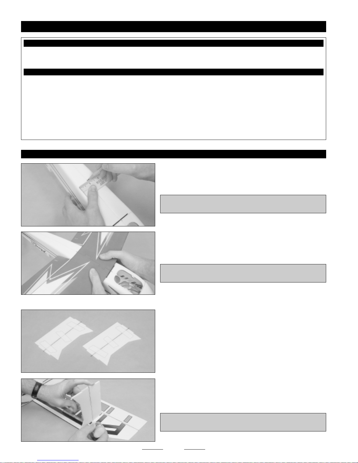
❑ Cut out the back of the cowling along the molded scribe line.
❑ Sand the back edge of the cowling smooth and straight.
6
Continued On Next Page

❑ Cut out the two molded air-intake holes in the front of the cowling,
then cut out the center of the cowling enough to clear the propeller
adapter on your motor.
❑ Install the cowling onto the fuselage, using three strips of clear
plastic tape - one on the top and one on each side. When aligned
properly, the front of the cowling should be centered around, and about
3/32" (2mm) behind, the front of the propeller adapter.
IMPORTANT It's normal for there to be a gap between the bottom
of the fuselage and the bottom of the cowling. This gap will be larger
the further forward the cowling is mounted.
SECTION 7: RUDDER HINGING AND DECAL INSTALLATION
YOU'LL NEED THE FOLLOWING PARTS FROM THE KIT:
❑ Rudder - 1
❑ Carbon Fiber Strip - 1
❑ 5 Minute Epoxy
❑ Wire Cutters
❑ Modeling Knife
❑ Scissors
❑ Ruler
❑ 220 Grit Sandpaper w/Sanding Block
❑ Masking Tape
STEP 1: HINGING THE RUDDER
❑ Decal Set - 1
YOU'LL NEED THE FOLLOWING TOOLS AND SUPPLIES:
❑ Waxed Paper
❑ Paper Towels
❑ Rubbing Alcohol
❑ Epoxy Mixing Sticks
❑ Epoxy Mixing Cups
❑ 3M 3/4" Clear Plastic Tape
❑ Sand a 45º bevel into the left side of the leading edge of the rudder.
❑ Cut a piece of carbon fiber strip to a length of 7-1/2" (191mm).
❑ Glue the carbon fiber strip to the trailing edge of the rudder, using 5
minute epoxy. Remove any excess epoxy using a paper towel and
rubbing alcohol, and use pieces of masking tape to hold the carbon
fiber strip in place.
IMPORTANT Make sure that the rudder is perfectly flat during the
drying process.
7
Continued On Next Page

STEP 2: APPLYING THE DECALS
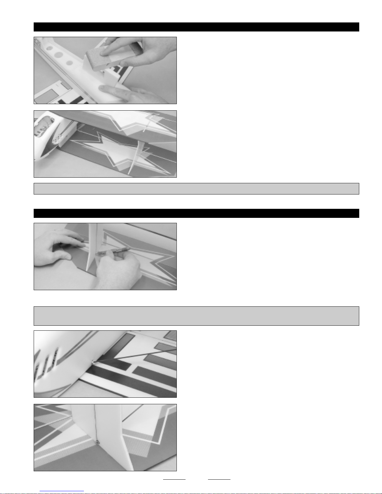
❑ While holding the rudder tight against the trailing edge of the
fuselage, apply a strip of clear plastic tape to the right side of the
hinge line.
IMPORTANT Make sure that when hinged the rudder has enough
movement. It should deflect 3" (75mm) each direction. If you hinge it
to tightly, it may restrict movement and you won't get full deflection.
❑ Turn the fuselage over and deflect the rudder left approximately 45º.
While holding the rudder at a 45º angle, apply a strip of clear plastic
tape to the left side of the hinge line.
❑ Push the tape gently down into the hinge line, then pivot the rudder
right and left to ensure free hinge movement in both directions.
❑ Cut out the decals and apply them to the fuselage sides. Begin by
applying the decal to the rudder, then slowly work forward, making sure
to keep the decal aligned. The front of the decal should be in the
approximate location shown. This means that the decal will overhang
the edges of the rudder. Simply cut off the excess.
SECTION 8: STABILIZER INSTALLATION
YOU'LL NEED THE FOLLOWING PARTS FROM THE KIT:
❑ Horizontal Stabilizer w/Elevator - 1
❑ Plywood Parts - 1
YOU'LL NEED THE FOLLOWING TOOLS AND SUPPLIES:
❑ Foam-Friendly Gap-Filling C/A
❑ 5 Minute Epoxy
❑ Aerosol Zip-Kicker
❑ Wire Cutters
❑ Modeling Knife
❑ Ruler
❑ Builder's Triangle
❑ 220 Grit Sandpaper w/Sanding Block
❑ Very carefully split the decals along each side of the rudder hinge
line, then cut away the decal from over the stabilizer mounting slots and
the servo mounting holes.
❑ Carbon Fiber Strips - 1
❑ Masking Tape
❑ Waxed Paper
❑ Paper Towels
❑ Rubbing Alcohol
❑ Epoxy Mixing Sticks
❑ Epoxy Mixing Cups
❑ 3M 3/4" Clear Plastic Tape
8
Continued On Next Page

STEP 1: INSTALLING THE STABILIZER
❑ Sand a 45º bevel into the bottom leading edge of the elevator.
The bottom has the light blue color scheme.
☞
❑ Glue one carbon fiber strip to the beveled leading edge, using the
same techniques that you used to glue the carbon fiber strip to the
rudder.
IMPORTANT Make sure that the elevator is flat and the leading
edge is straight while the glue cures.
❑ Glue one carbon fiber strip to the trailing edge of each elevator half
and to the trailing edge of the stabilizer. Again, make sure that the parts
are flat while the glue cures.
❑ Glue the plywood elevator support plate to the bottom of the
elevator, making sure that the slot in the support plate lines up with the
control horn mounting slot in the elevator.
❑ Slide the elevator into the stabilizer mounting slot, making sure that
the top of the elevator is toward the top of the fuselage.
IMPORTANT You MUST slide the elevator into place BEFORE
installing the stabilizer. If you don't, it will be impossible to install the
elevator after the stabilizer is glued in place.
❑ Draw a centerline mark on the trailing edge of the stabilizer.
9
Continued On Next Page

STEP 2: HINGING THE ELEVATOR
❑ Slide the stabilizer into the fuselage and align it, using the notch in
the leading edge and the centerline mark that you drew as a reference.
IMPORTANT The stabilizer should be aligned 90º to the fuselage,
too. Use a builder's triangle to check this.
❑ When satisfied with the alignment, glue the stabilizer to the fuselage,
using foam-friendly C/A.
IMPORTANT Make sure to apply a bead of glue to all four joints
and use a builder's triangle to ensure that the stabilizer is aligned
90º to the fuselage.
❑ Hinge the elevator to the stabilizer, using the same techniques that
you used to hinge the rudder to the fuselage.
SECTION 9: BOTTOM AND TOP WING ASSEMBLY
YOU'LL NEED THE FOLLOWING PARTS FROM THE KIT:
❑ Top Wing Halves w/Ailerons - 2
❑ Bottom Wing Halves w/Ailerons - 2
YOU'LL NEED THE FOLLOWING TOOLS AND SUPPLIES:
❑ 5 Minute Epoxy
❑ Wire Cutters
❑ Modeling Knife
❑ Ruler
❑ 220 Grit Sandpaper w/Sanding Block
❑ Masking Tape
STEP 1: JOINING THE BOTTOM WING HALVES
❑ Glue the two bottom wing halves together, making sure that they
are flat.
❑ Carbon Fiber Strips - 4
❑ Waxed Paper
❑ Paper Towels
❑ Rubbing Alcohol
❑ Epoxy Mixing Sticks
❑ Epoxy Mixing Cups
❑ 3M 3/4" Clear Plastic Tape
IMPORTANT The center section of the bottom wing halves, at the
leading and trailing edges, is straight to match the bottom of the
fuselage. Make sure that you're joining the bottom halves and not
the top halves.
10
Continued On Next Page

❑ Cut one carbon fiber strip to a length of 23-1/2" (597mm).
❑ Glue the 23-1/2" (597mm) long carbon fiber strip to the leading edge
of the wing and a second carbon fiber strip to the trailing edge, using the
same techniques that you used to glue the carbon fiber strips to the
stabilizer assembly. Again, make sure that you hold the wing flat while
the glue cures.
IMPORTANT Install the carbon fiber strips as one piece. Do not cut them in half for each half of the wing. They are flexible
enough to bend around the contour of the wing center section and will provide the greatest strength this way.
STEP 2: HINGING THE AILERONS
❑ Sand a 45º bevel into the bottom of the leading edge of both bottom
wing ailerons. The bottom of the ailerons is solid blue.
IMPORTANT The bottom wing ailerons have one precut slot in each aileron. The top wing ailerons have two precut slots each.
Double-check that you're working with the bottom wing ailerons.
❑ Glue one carbon fiber strip to the trailing edge of each aileron. Again,
make sure to hold the ailerons flat while the glue cures.
❑ Hinge the ailerons to the wing, using the same techniques that you
used to hinge the rudder and the elevator.
STEP 3: TOP WING ASSEMBLY
❑ Repeat the previous steps to join the top wing halves, install the
carbon fiber strips and hinge the ailerons.
11
SECTION 10: WING MOUNTING
YOU'LL NEED THE FOLLOWING PARTS FROM THE KIT:
❑ Wing Struts - 2
❑ Plywood Parts - 1
YOU'LL NEED THE FOLLOWING TOOLS AND SUPPLIES:
❑ Foam-Friendly Gap-Filling C/A
❑ 5 Minute Epoxy
❑ Aerosol Zip-Kicker
❑ Wire Cutters
❑ Electric or Hand Drill
❑ 1/16" (1.6mm) Drill Bit
❑ Ruler
❑ Pencil
❑ Carbon Fiber Rods - 4
❑ Carbon Fiber Strips - 1
❑ Builder's Triangle
❑ 220 Grit Sandpaper w/Sanding Block
❑ Masking Tape
❑ Waxed Paper
❑ Paper Towels
❑ Rubbing Alcohol
❑ Epoxy Mixing Sticks
❑ Epoxy Mixing Cups
STEP 1: MOUNTING THE BOTTOM WING AND INSTALLING THE WING STRUTS
❑ Draw a centerline at the front and back of the wing mounting area on
the bottom of the fuselage.
IMPORTANT Do not use the fuselage joint line to center the wing.
This line may not actually be centered.
❑ Glue the bottom wing to the fuselage, making sure to line up the
centerline of the wing with the centerline marks you drew.
IMPORTANT Make sure that the wing is pushed back far enough
so that the leading edge doesn't cover the landing gear mounting slot.
❑ Cut two pieces of the carbon fiber strip to a length of 6-1/4" (159mm).
❑ Glue one carbon fiber strip between the front and back halves of
each wing strut.
❑ Glue the two wing struts to the top of the wing, making sure that the
front edge of the struts is even with the leading edge. Use a builder's
triangle to make sure that the wing struts are perpendicular to the wing.
IMPORTANT Note the direction the wing struts are mounted. They
should both be angled forward when viewed from the side.
12
Continued On Next Page
STEP 2: MOUNTING THE TOP WING
❑ Very lightly sand the top of the center wing mount to ensure that it's
perfectly flat.
❑ Glue the top wing to the center wing mount and the wing struts. To
make alignment easier, do this with the airplane upside down. First, put
the two wing struts into the slots in the top wing, then center the center
wing mount over the centerline of the top wing. The front edge of the
wing struts should be even with the leading edge and the back edge of
the center wing mount should be even with the trailing edge.
IMPORTANT Use a couple of weights to gently hold the wings flat and in alignment until the glue cures.
STEP 3: INSTALLING THE CARBON FIBER SUPPORT RODS
❑ Turn the airplane upside down and drill a 1/16" (1.6mm) diameter
hole through the top of one wing strut, just in front of the carbon fiber
support strip. Position the hole 1/4" (6mm) up from the surface of the
wing and angle the hole up, as shown.
❑ Cut one piece of carbon fiber rod to a length of 11-1/4" (286mm).
PRO TIP Before installing the plywood collars that secure the carbon fiber rods into place, we sanded an angle into one side of
them, so that they fit tight against the fuselage and struts. Do this to a total of 6 plywood collars.
❑ Push one end of the carbon fiber rod into the predrilled hole in the
fuselage side, then slide one plywood collar onto the carbon fiber rod
and push the other end of the carbon fiber rod through the hole you
drilled in the wing strut.
❑ Adjust the carbon fiber rod so that 1/4" (6mm) sticks out past the
outside of the wing strut, then glue the carbon fiber rod and plywood
collar to the fuselage.
❑ Turn the airplane back upside down and make sure that the wings
are flat, then glue the carbon fiber rod and a plywood collar to the
outside of the wing strut.
13
Continued On Next Page

❑ Cut one piece of carbon fiber rod to a length of 13-1/4" (337mm).
❑ Install the carbon fiber rod, using the same techniques that you used
to install the first carbon fiber rod. Install one end of the carbon fiber rod
through the bottom of the wing strut and the other end through the
center wing mount.
IMPORTANT Position the carbon fiber rod 5/8" (16mm) behind the
front edge of the center wing mount.
❑ Repeat the previous procedures to install the two carbon fiber rods
on the other side of the airplane.
SECTION 11: CONTROL SYSTEMS INSTALLATION
YOU'LL NEED THE FOLLOWING PARTS FROM THE KIT:
❑ Plywood Parts - 1
❑ Carbon Fiber Rods - 1
❑ Plain Wires - 2
YOU'LL NEED THE FOLLOWING TOOLS AND SUPPLIES:
❑ Thin C/A
❑ 5 Minute Epoxy
❑ Heat Gun
❑ # 1 Phillips Head Screwdriver
❑ Wire Cutters
❑ Needle Nose Pliers
❑ Z-Bend Pliers
❑ Modeling Knife
❑ Heat-Shrink Tubing - 1
❑ Carbon Fiber Strips - 1
❑ Hand Drill with 1/16" (1.6mm) Drill Bit
❑ Ruler
❑ Pencil
❑ 220 Grit Sandpaper w/Sanding Block
❑ Paper Towels
❑ Rubbing Alcohol
❑ Epoxy Mixing Sticks
❑ Epoxy Mixing Cups
STEP 1: INSTALLING THE ELEVATOR AND RUDDER CONTROL SYSTEMS
❑ Cut away the decal from over the servo mounting hole in the right
side of the fuselage, then install your servo.
IMPORTANT We positioned the servo output shaft toward the front
of the airplane, so that we didn't have to install a servo extension to
reach the cockpit. You may need to install an extension if your servo
lead is shorter than normal.
❑ Glue one plywood control horn into the precut slot in the bottom of
the elevator.
14
Continued On Next Page
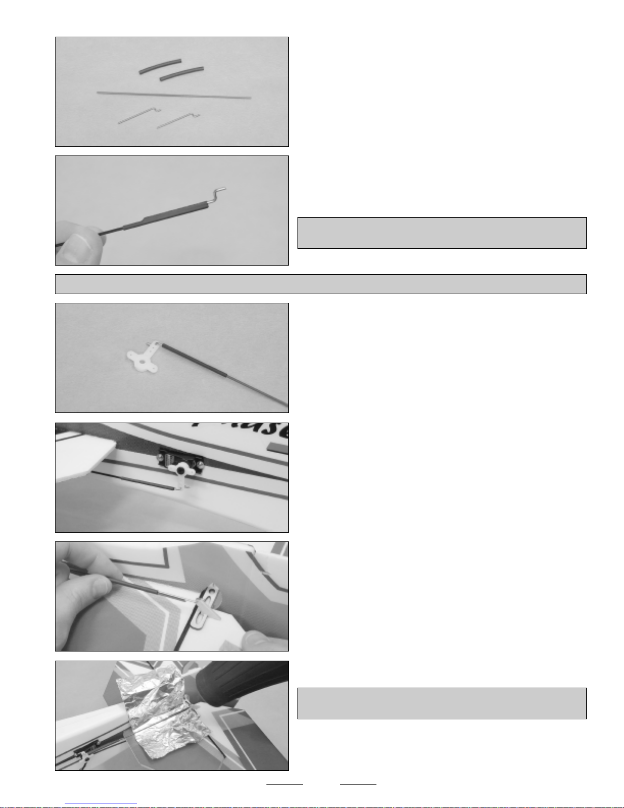
❑ Cut two pieces of heat-shrink tubing to a length of 1-1/2" (38mm),
then cut one piece of carbon fiber rod to a length of 5" (127mm).
❑ Cut two pieces of plain wire to a length of 1-1/2" (38mm), then make
a Z-Bend in one end of each piece of wire.
❑ Secure one piece of wire to one end of the carbon fiber rod, using
one piece of heat-shrink material. Heat the heat-shrink material with a
heat gun to shrink it into place.
IMPORTANT For extra security, apply a few drops of thin C/A to the
end of the pushrod and allow it to "wick" into the joint.
IMPORTANT The piece of wire should overlap the carbon fiber rod at least 1" (25mm).
❑ Install the pushrod into the outermost hole in your servo arm.
❑ Center the elevator servo, then attach the servo arm to the servo,
making sure that it's centered and pointing down.
❑ Slide the second piece of heat-shrink tubing over the carbon fiber
rod, then attach the second piece of wire to the control horn.
❑ Center both the elevator servo and the elevator, then slide the
heat-shrink tubing over the wire.
❑ Place a piece of tinfoil between the pushrod and the airplane.
IMPORTANT The tinfoil will prevent the heat-gun from damaging
the decal and/or foam. Do not omit this step.
❑ Double-check that both the elevator servo and the elevator are
centered, then use a heat-gun to shrink the heat-shrink tubing and
apply a few drops of thin C/A to the joint for extra security.
15
Continued On Next Page

❑ Install the rudder control system, using the same techniques that
you used to install the elevator control system. The only difference is
that you should cut the piece of carbon fiber rod to a length of 7-1/2"
(191mm).
STEP 2: INSTALLING THE AILERON CONTROL SYSTEM
❑ Center your aileron servo, then install the servo horn onto the servo,
making sure that it's centered, too.
❑ Install your aileron servo into the center wing mount and secure it
into place, using a couple of dabs of 5 minute epoxy.
IMPORTANT You'll need to trim the opening to fit the servo
mounting lugs and the servo lead.
❑ Cut a slot in the top of the fuselage and run the servo lead into
the cockpit.
❑ Cut two pieces of plain wire to a length of 4" (102mm), then make a
Z-Bend in one end of each piece of wire.
❑ So that you can adjust the length of the pushrod after it's installed,
carefully make a V-Shaped bend 3/4" (19mm) behind the Z-Bends.
❑ Install the pushrods into the outermost holes in the servo arm.
16
Continued On Next Page

❑ Temporarily install the remaining two plywood control horns into the
slot in each aileron.
IMPORTANT Do not glue the control horns into place yet.
❑ Center both the aileron servo and both ailerons, then draw a mark
on the pushrod wires where they cross the hole in the control horns.
❑ Remove the control horns and pushrod wires, then make a Z-Bend
in each pushrod wire at the mark you drew.
❑ Connect the control horns to the pushrod wires, install the pushrod
wires back onto the servo arm, then glue the control horns into the
ailerons.
IMPORTANT The V-Shaped bend will allow you to center both ailerons independently. Make the bend wider to lengthen the
pushrod wire and make the bend narrower to shorten the pushrod wire.
STEP 3: INSTALLING THE AILERON LINK RODS
SECTION 12: CANOPY INSTALLATION
YOU'LL NEED THE FOLLOWING PARTS FROM THE KIT:
❑ Canopy - 1
❑ Plywood Parts - 1
❑ Glue one plywood link rod mount into the precut slot in the top of the
bottom wing aileron, then glue a second plywood link rod mount into the
precut slot in the bottom of the top wing aileron.
❑ Center the top wing ailerons (if necessary, adjust the V-Shaped bends
as described in step # 2), then center the bottom wing ailerons.
❑ Assemble and install the aileron link rods, using the same techniques
that you used to assemble and install the elevator and rudder pushrods.
Cut the two carbon fiber rods to a length of 5-1/2" (140mm).
❑ Magnets - 2
YOU'LL NEED THE FOLLOWING TOOLS AND SUPPLIES:
❑ 5 Minute Epoxy
❑ Modeling Knife
❑ 220 Grit Sandpaper w/Sanding Block
❑ Paper Towels
❑ Rubbing Alcohol
❑ Epoxy Mixing Sticks
❑ Epoxy Mixing Cups
17
Continued On Next Page

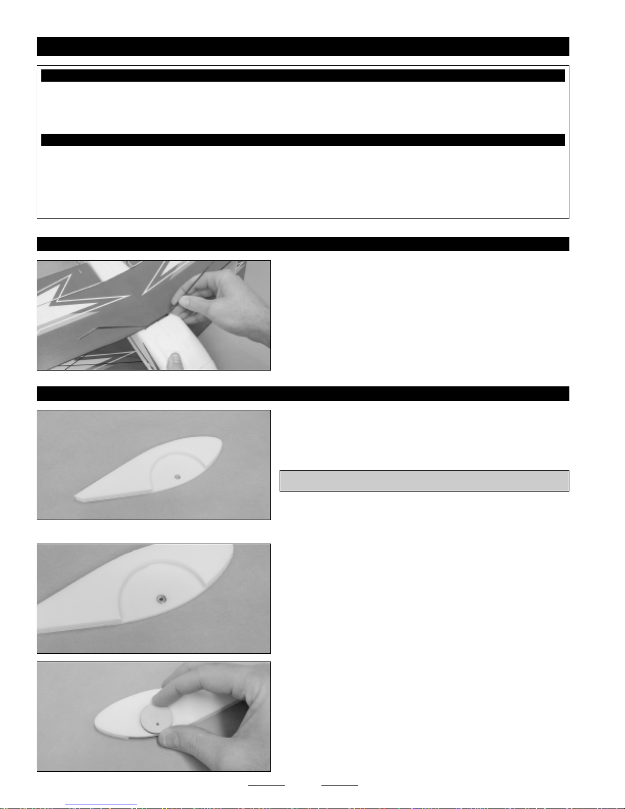
STEP 1: INSTALLING THE CANOPY SUPPORTS
STEP 2: INSTALLING THE CANOPY LATCH ASSEMBLY
❑ Glue the two plywood forward support pieces together, then glue the
support assembly to the front of the canopy.
❑ Glue the two plywood side supports to the fuselage sides.
IMPORTANT Be careful not to accidentally glue the plywood latch
to the fuselage side. The plywood latch has a small precut hole for
the magnet. The two supports have larger precut lightening holes.
❑ Glue one magnet into the back of the canopy. Position the magnet
1/4" (6mm) from the back edge of the canopy and cut a shallow recess
for the magnet to set in, so that it's flush with the inside of the canopy.
❑ Glue the second magnet into the matching hole in the plywood latch.
❑ Glue the latch assembly to the top of the fuselage. Position the latch
so that the center of the magnet is 1/4" (6mm) from the edge of the
fuselage and double-check that the latch is centered.
❑ Install the canopy onto the fuselage.
You may need to sand the edges of the canopy for a perfect fit.
☞
18
SECTION 13: ESC, RECEIVER AND BATTERY INSTALLATION
YOU'LL NEED THE FOLLOWING PARTS FROM THE KIT:
❑ Velcro - 1
YOU'LL NEED THE FOLLOWING TOOLS AND SUPPLIES:
❑ Wire Cutters
❑ Scissors
❑ Hand Drill with 5/64" (2mm) Drill Bit
STEP 1: INSTALLING THE ESC
STEP 2: INSTALLING THE RECEIVER
❑ Battery Cover - 1
❑ 30 Watt Soldering Iron
❑ Solder
❑ Heat-Shrink Tubing (Assorted Sizes)
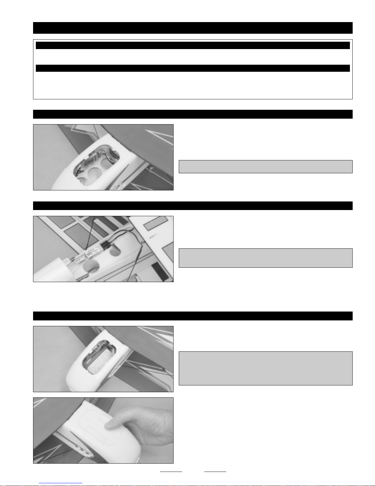
❑ Mount your ESC to the fuselage side in the battery compartment,
using a piece of Velcro.
IMPORTANT Run the ESC throttle lead up into the cockpit.
❑ Plug the elevator, rudder, aileron and ESC leads into your receiver,
then mount the receiver to the cockpit deck, using a piece of Velcro.
IMPORTANT You may need to install a 6" (152mm) servo extension
on one or more of the servo leads.
❑ Run the antenna down through the cockpit deck and out the bottom of the fuselage. Secure the end of the antenna to the back
of the fuselage, using a couple of pieces of clear tape.
STEP 3: INSTALLING THE BATTERY
❑ Install your battery into the battery compartment, using a piece
of Velcro.
PRO TIP Depending on the weight of your battery you may need to
mount it under the canopy and move your receiver into the battery
compartment. This arrangement may be necessary if the battery you're
using is very heavy or the motor is very light.
❑ Install the battery cover. For convenience, we hinged one side of
the battery cover to the fuselage, using a strip of clear tape. We then
fashioned a latch out of a second piece of clear tape to hold the battery
cover closed. If you use this method, apply a strip of clear tape to the
fuselage, where the "tape latch" will stick. This will make the "tape latch"
stick better and last longer.
19
SECTION 14: LANDING GEAR INSTALLATION
YOU'LL NEED THE FOLLOWING PARTS FROM THE KIT:
❑ Wheels - 2
❑ Landing Gear Wire - 1
❑ Strut Covers - 2
YOU'LL NEED THE FOLLOWING TOOLS AND SUPPLIES:
❑ Foam-Friendly Gap-Filling C/A
❑ 5 Minute Epoxy
❑ Modeling Knife
❑ 220 Grit Sandpaper w/Sanding Block
❑ Paper Towels
STEP 1: INSTALLING THE LANDING GEAR WIRE
❑ Wheel Covers - 6
❑ Wheel Cover Supports - 3
❑ Plywood Parts - 1
❑ Rubbing Alcohol
❑ Epoxy Mixing Sticks
❑ Epoxy Mixing Cups
❑ 3M 3/4" Clear Plastic Tape
❑ Roughen the gluing surfaces of the landing gear wire, then apply a
generous amount of glue to the gluing surfaces of the wire.
❑ Push the landing gear wire firmly down into the mounting slot,
making sure that it's straight when viewed from the front.
STEP 2: INSTALLING THE WHEEL COVERS AND WHEELS
❑ Glue two outer wheel cover sections to one inner wheel cover section,
making sure that the edges are even with each other.
IMPORTANT Be sure to make one right and one left.
❑ After the glue dries, use 220 grit sandpaper with a sanding block to sand the edges smooth and even.
❑ Glue one plywood collar into the precut hole in each wheel cover
assembly.
❑ Glue one plywood wheel cover support to the inside (flat side) of
each wheel cover assembly, making sure to align the precut hole in the
plywood supports with the precut hole in the plywood collars.
20
Continued On Next Page

❑ Slide one wheel cover assembly onto each axle, followed by one
wheel and one plywood collar.
❑ Double-check that the wheels spin freely, then apply a dab of glue to
only the plywood collars to keep them from coming off.
STEP 3: INSTALLING THE STRUT COVERS
IMPORTANT The back of the strut covers is cut straight and the front is cut at an angle. In the next procedure, make sure that
the straight edge (the back) is glued to the landing gear wire.
❑ Carefully glue the strut covers to both the front of the landing gear
wire and to the side of the wheel covers.
Before the glue dries, make sure that the wheel covers are aligned
☞
properly. When the airplane is resting on its landing gear, the bottom
edge of the wheel covers should be parallel to the ground.
❑ To strengthen the glue joint, apply a strip of clear plastic tape (not
included) around the landing gear wire and onto the strut covers.
❑ Carefully glue one foam wheel cover support piece into place to
strengthen the joint between the wheel cover and the strut cover.
This completes the assembly of your new Fidget 3D EP
Biplane. Please see the next page for balancing,
control throws and flight setup information.
21

SECTION 15: BALANCE POINT, CONTROL THROWS AND FLIGHT SETUP INFORMATION
BALANCE POINT:
The Center of Gravity (C/G or Balance Point) range is 2-3/4"-3-1/2" (70mm-90mm), measured on the top wing, at the
sides of the center wing mount.
For test flying, we suggest that you start with the balance point at 3" (76mm). As you become more familiar with the
flight characteristics, you can move the balance point further back. For 3D flying, you will probably want to set the
balance point at 3-1/2" (90mm). We don't suggest moving the balance point any further back than that, though.
CONTROL THROWS:
Sport Flying
3D Flying
Ailerons: 5/8" (15mm) Up & Down
Elevator: 3/4" (20mm) Up & Down
Rudder: 1-7/8" (50mm) Right & Left
THE CONTROL THROWS ARE MEASURED FROM THE WIDEST POINT OF THE CONTROL SURFACES
EXPONENTIAL:
Sport Flying
Ailerons: 35%
Elevator: 35%
Rudder: 35%
Exponential softens the response of the control surfaces around neutral stick. This makes the airplane easier to control
while using such large control throws. The Exponential values shown are given as a percent. Please note that different
brands of radio control systems may call for + or - Expo. Please check your transmitter's owners manual for more info.
MOTOR THRUST:
Down thrust should be adjusted in relation to C/G to achieve consistent elevator trim, regardless of throttle setting, and
should be, as much as possible, the same trim when inverted. Right thrust should be adjusted for hovering. Add a
sufficient amount of right thrust so that the rudder trims straight and the airplane pulls straight up on vertical lines. The
correct amount of right thrust will also help stabilizer the yaw axis during hover, too.
Ailerons: 1-3/16" (30mm) Up & Down
Elevator: 1-3/8" (35mm) Up & Down
Rudder: 3" (75mm) Right & Left
3D Flying
Ailerons: 60%
Elevator: 50%
Rudder: 50%
SECTION 16: PREFLIGHT CHECK AND SAFETY
●
Check the operation of the throttle. To do this, do the following:
A) Plug the flight battery into the ESC and turn on the radio system.
WARNING Do not turn the receiver on unless the transmitter is turned on first. Always turn the transmitter on first. Never allow
hands or clothing to get in the way of the propeller when the radio is turned on. Sudden unwanted radio signals, or turning the
radio on with the throttle stick set at full throttle, can turn the motor on unintentionally. Always make sure that the throttle control
stick is set to idle before turning on the transmitter.
B) When the throttle control stick is at the idle position, the motor should be off. Moving the stick forward should turn on the
motor. Gradually moving the stick to the full forward position should result in the motor running at full power.
Some ESCs will give you more proportional control than others. Your ESC may also have a manual control adjustment screw
☞
that must be adjusted prior to using the ESC. (Refer to your ESC's operating guide for further information.)
●
Check the condition of the transmitter batteries. They should be fully charged.
22
Continued On Next Page

PREFLIGHT CHECK AND SAFETY, CONTINUED....
●
Check every bolt and every glue joint in the airplane to ensure that everything is tight and well-bonded. This should
include all of the control surface hinges as well.
●
Double-check that you've installed and tightened all of the servo horn retaining screws.
●
Double-check that the battery is properly secured into the fuselage. There's nothing worse than the battery coming loose
during flight.
●
Double-check the balance of the airplane. Do this with the battery installed and the airplane ready to fly.
●
Check the control surfaces. They should all move in the correct direction and not bind.
●
Make sure that you've installed 1/4" long pieces of silicone tubing over the clevises to prevent any chance of them opening
during flight.
●
If your radio transmitter is equipped with dual rate switches, double-check that they are on the low-rate setting for your first
few flights.
●
Check to ensure that all of the control surfaces are moving the proper amount in both low and high rate settings.
●
Check the receiver antenna. It should be fully extended and not coiled up inside the fuselage. Do not cut the receiver antenna
shorter or the range of your radio control system will be greatly reduced.
●
Properly balance the propeller. A propeller that is out of balance will cause excessive vibration, which could lead to engine
and/or airframe failure, and it will reduce engine efficiency and power.
●
You should complete a successful range check of your radio equipment prior to each new day of flying, or prior to the first flight
of a new or repaired model.
●
When flying at a flying field with established rules, you should abide by those rules. You should not deliberately fly your model
in a reckless and/or dangerous manner.
●
You should perform your initial turn after take- off away from the flightline and/or spectator area.
●
While flying, you should not deliberately fly behind the flight line. If your model should inadvertently fly behind the flight line, you
should change course immediately.
●
You should not knowingly operate your R/C radio system within 3 miles of a preexisting model club flying field without a
frequency sharing agreement with that club.
SECTION 17: REPLACEMENT PARTS LIST
When it comes time to order replacement parts, we recommend ordering directly from your local hobby retailer.
If your hobby retailer does not stock Phase3 Models products, you can order replacement parts directly
from your local distributor, using the Customer Service Information on the back page.
Instruction Manual .................................................... PH109211
Fuselage Set ............................................................. PH109212
Flat Foam Parts ........................................................ PH109213
Carbon Fiber Strips ................................................... PH109214
Carbon Fiber and Metal Rods .................................. PH109215
Landing Gear ............................................................ PH109216
Wood Accessories Set .............................................. PH109217
Cowling ..................................................................... PH109218
23

FOR CUSTOMER SERVICE, PLEASE CONTACT YOUR REGIONAL DISTRIBUTOR, LISTED BELOW:
In North America:
Global Services
18480 Bandilier Circle
Fountain Valley, CA 92708
Phone: (714) 963-0329
Fax: (714) 964-6236
Email: service@globalhobby.net
In Europe:
Ripmax LTD.
241 Green Street
Enfield, U.K.
EN3 7SJ
Phone: (0) 20 8282-7500
Fax: (0) 20 8282-7501
Email: mail@ripmax.com
24
 Loading...