

Page 1
ASSEMBLY INSTRUCTIONS
IMPORTANT Before beginning assembly, please read and understand the warnings listed on the next page.
Failure to read and understand these warnings could lead to bodily harm and/or injury. The Phase 3 Models Squall EDF, is
not intended for those under 14 years of age, unless closely supervised by an adult.
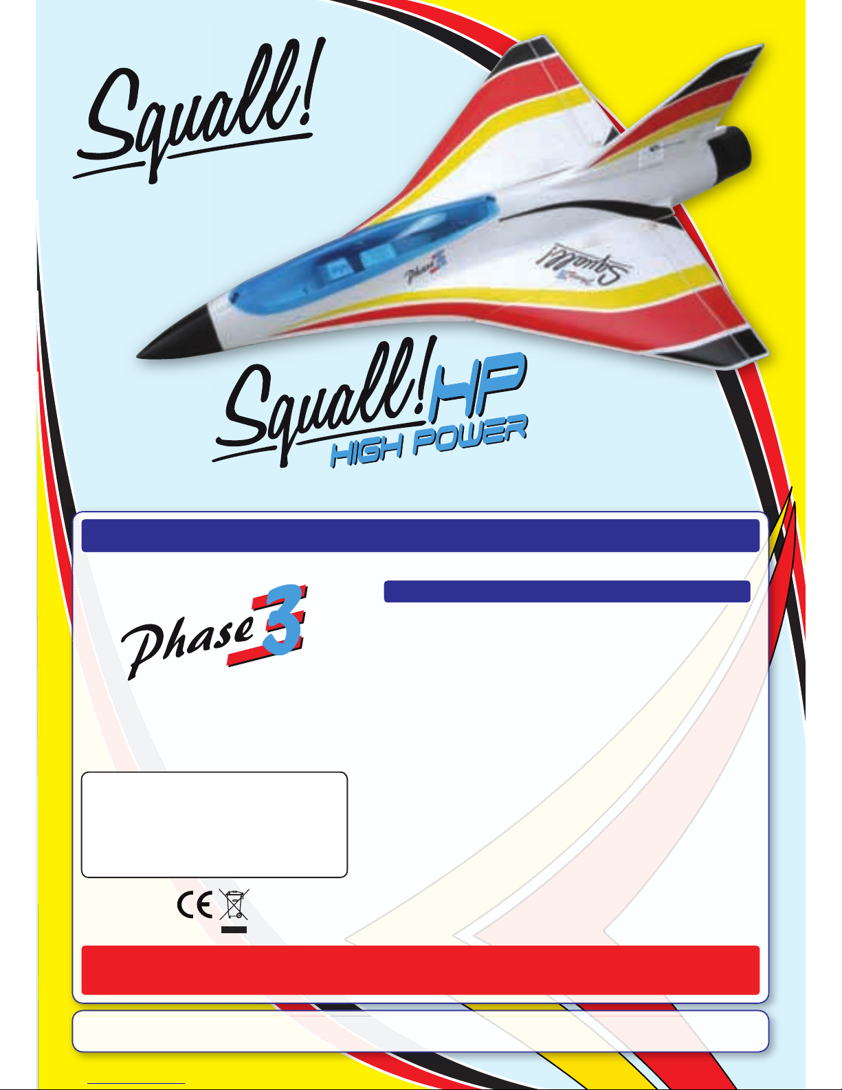
Includes High-Performance
Brushless Motor, Ducted Fan
Assembly and Brushless
Electronic Speed Controller
SPECIFICATIONS AND FEATURES
Wingspan: 650mm (25.6”)
Length: 885mm (34.8”)
Weight RTF: Squall! 600~650g (21.2~22.9oz)
Squall! HP 650~780g (22.9~27.5oz)
Motor RPM: 45,000~50,000
Motor: Squall! - 3800KV (11.1v) Brushless
Squall! HP - 3400KV (14.8v) Brushless
ESC: Squall! - 40A (11.1v) Brushless
Squall! HP - 45A HP (14.8v) Brushless
Radio Required: 4 channel with elevon mixing and three
9~10g micro servos
Battery Required: Squall! - 3 cell 2500mAh 20C Li-Po
Squall! HP - 4 cell 2500mAh 20C Li-Po
• Moulded Lightweight Airframe
• High-Efficiency Ducted Fan Unit Included
• High-RPM Brushless Motor Included
• 45 Amp Brushless Speed Controller Included
• Extensive Decal Sheet Included
• Fast and Easy Assembly
• Over 100 High-Resolution Colour Photos to Guide You
CAUTION The Phase 3 Models Squall EDF is designed for intermediate to advanced pilots. It is not intended for beginners.
It is not a trainer!
High performance EDF model with
3800KV motor and 5 bladed fan
for 3 cell Li-Po batteries.
Super-high performance EDF model with 3400KV
motor and 3 bladed fan for 4 cell Li-Po batteries.
4 Cell Version
3 Cell Version
© 2009, Phase 3 Models - All Rights Reserved
Version 1 May 2009
Phase 3 Models
P.O. Box No. 402
Texaco Road PO
New Territories, Hong Kong
Made in Taiwan
Squall! EDF ARTF - Product Number PH019
Squall! HP EDF ARTF - Product Number PH020
Page 2
Page 2
FOR YOUR SAFETY - PLEASE READ AND UNDERSTAND THESE WARNINGS!
fly
the
same
frequency
fly
from
the
Always
fly
free
from
flying,
that
behind
the
careful
to
to
the
is
to
that
using
fresh
fully
the
to
lose
the
to
the
components
components
the
the
to
wet
of
to
new
flying,
to
the
first
flight
a
to
will
the
foam
and
to
from
the
the
turn
transmitter
turning
the
the
the
turn
the
turning
the
transmitter.
the
when
flying
the
the
the
the
lose lose lose
the
the
flight.
flying
flying
flying
the
transmitter
antenna
to
of
the
the
GENERAL WARNINGS
RADIO SYSTEM WARNINGS
fire.
injury
from
loss
fire
from
misuse
this
warnings
followed
times.
to
to
fire.
this
understanding
warnings.
the
storage
voltage
for
pack
followed.
wet
to
the
the
outdoors
firesafe
the
when
in
the
the
warnings
the
the
uses
the
firesafe
when
the
for
or
the
MUST
the
then
battery
to
discharge.
the
to
poke,
the The
for
LITHIUM POLYMER BATTERY WARNINGS
YOU MUST READ THIS BEFORE CHARGING
YOUR BATTERY
INTRODUCTION
casing
the
degrees
Thank you for purchasing the Phase 3
the final assembly of your new aircraft,
Page 3
Page 3
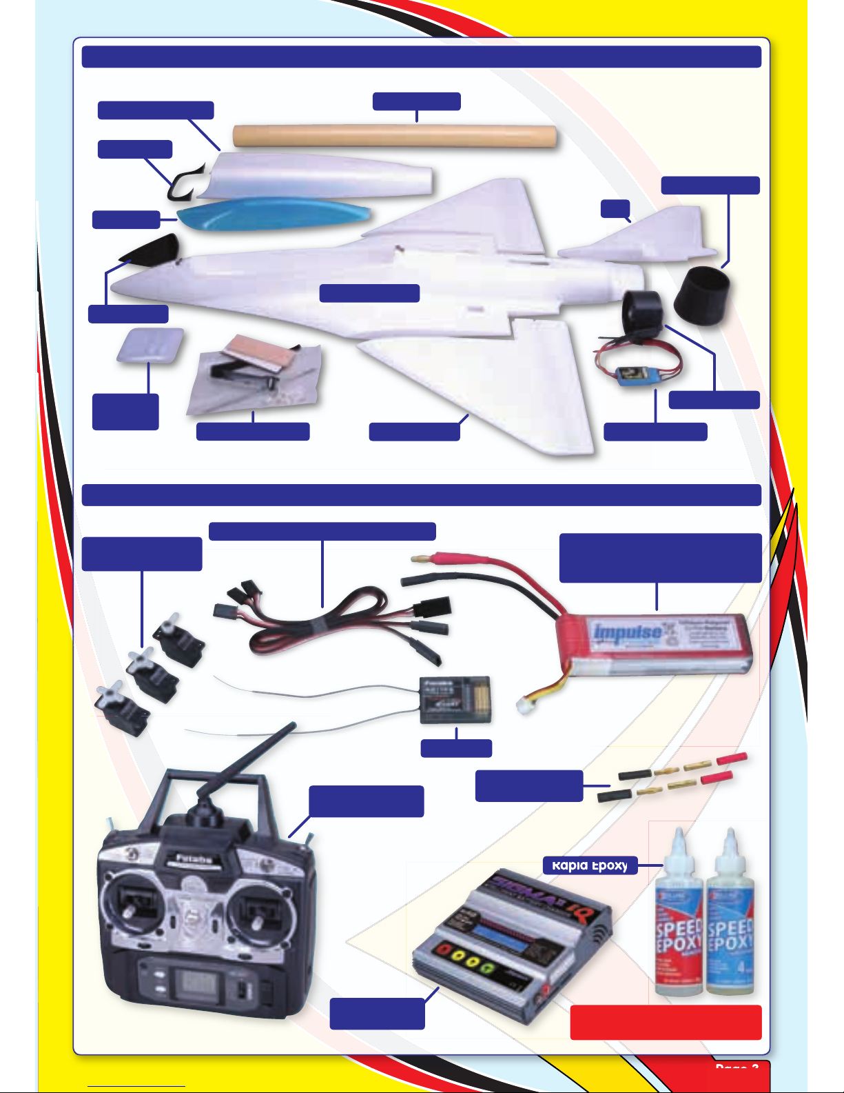
SQUALL - KIT CONTENTS
Decal Sheet
Fuselage Bottom
Canopy
Wing Panels
Fin
Ducted Fan
Brushless ESC
Exhaust Cone
Fuselage Top
Hardware Pack
ITEMS REQUIRED TO COMPLETE THE SQUALL
LiPo Battery
Squall! - 3S 2500mAh 20C or
Squall! HP - 4S 2500mAh 20C
Receiver
3 x 300mm Servo Extension Leads
3 x Micro Servos
9 - 10g
Rapid Epoxy
4mm Gold
Connectors
Transmitter with
Elevon Mixing
LiPo Battery
Charger
DO NOT USE SOLVENTS OR
CYANOACRYLATE (C/A) GLUE
Servo
Covers
Nose Cone
Intake Lip
Page 4
Page 4
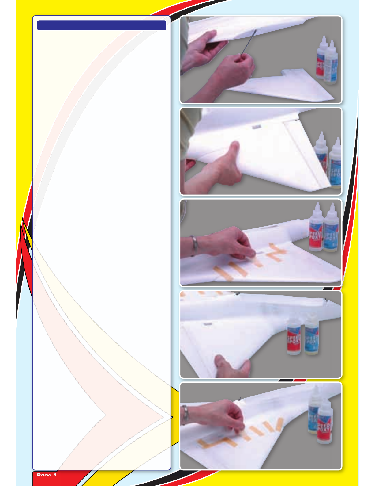
Step 1
Mix up a quantity of rapid epoxy and
apply to the wing root ensuring that it is
thoroughly coated.
Step 2
Push the wing panel firmly against the
mating surfaces of the fuselage ensuring
that it is correctly aligned.
Step 3
Apply strips of tape to hold the wing in
place as the epoxy cures. Wipe off any
excess adhesive before it sets.
Step 4
Repeat the process for the second wing
panel, again using sufficient rapid epoxy.
Step 5
Apply strips of tape to hold the wing in
place as the epoxy cures.
ASSEMBLING THE SQUALL EDF
Page 5
Page 5
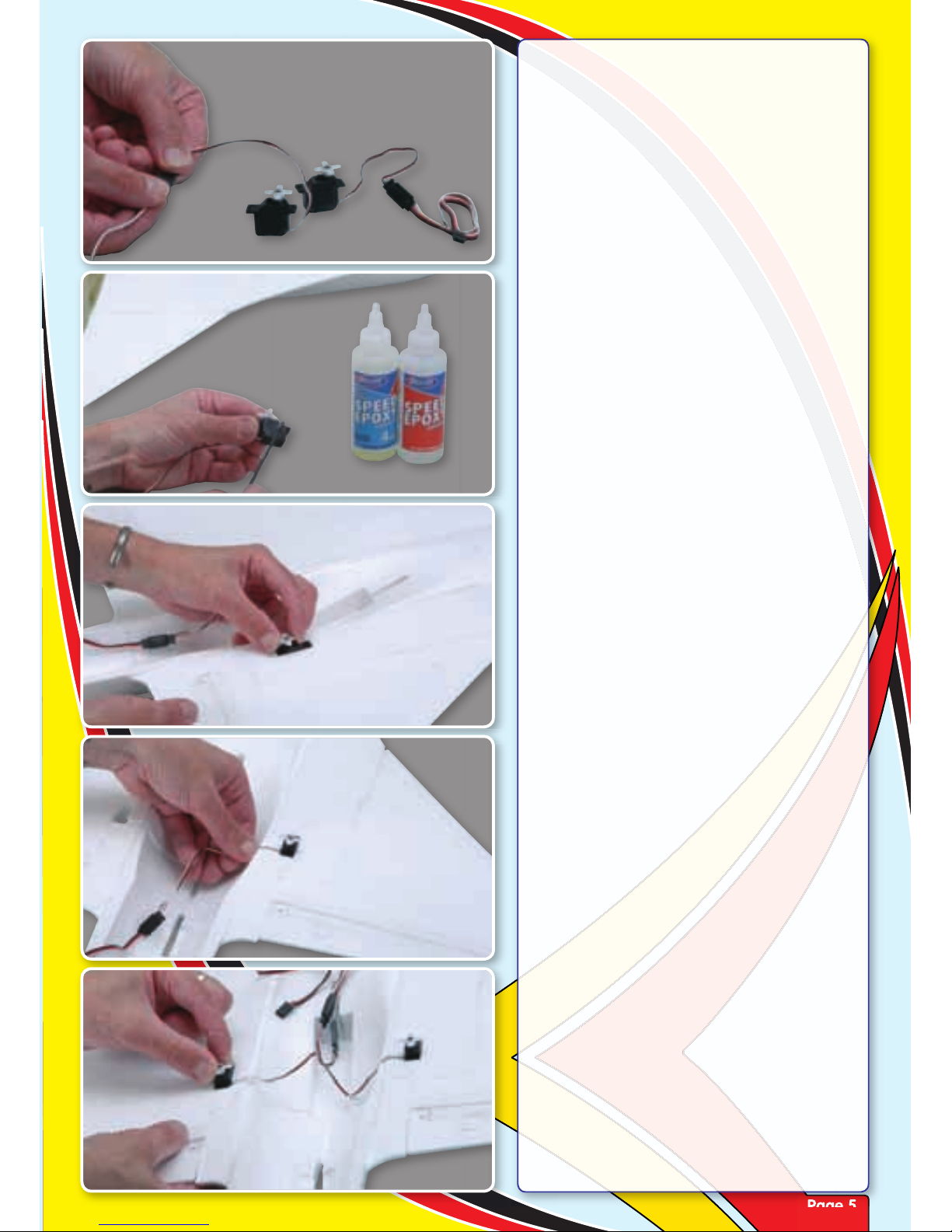
Step 6
Prepare your elevon servos by connecting
a pair of 300mm extension leads.
Step 7
Test fit the servo in its moulded cut-out,
then apply a smear of epoxy to the servo.
Step 8
Push the servo into position ensuring that
the lead exits in its moulded slot and the
output horn is to the rear.
Step 9
Ensure that there is no excess lead trapped
under the servo through the surface of the
wing by gently pulling the lead taut.
Step 10
Glue the second servo in position, again
ensuring the lead is pulled down into its
moulded slot.
Page 6
Page 6
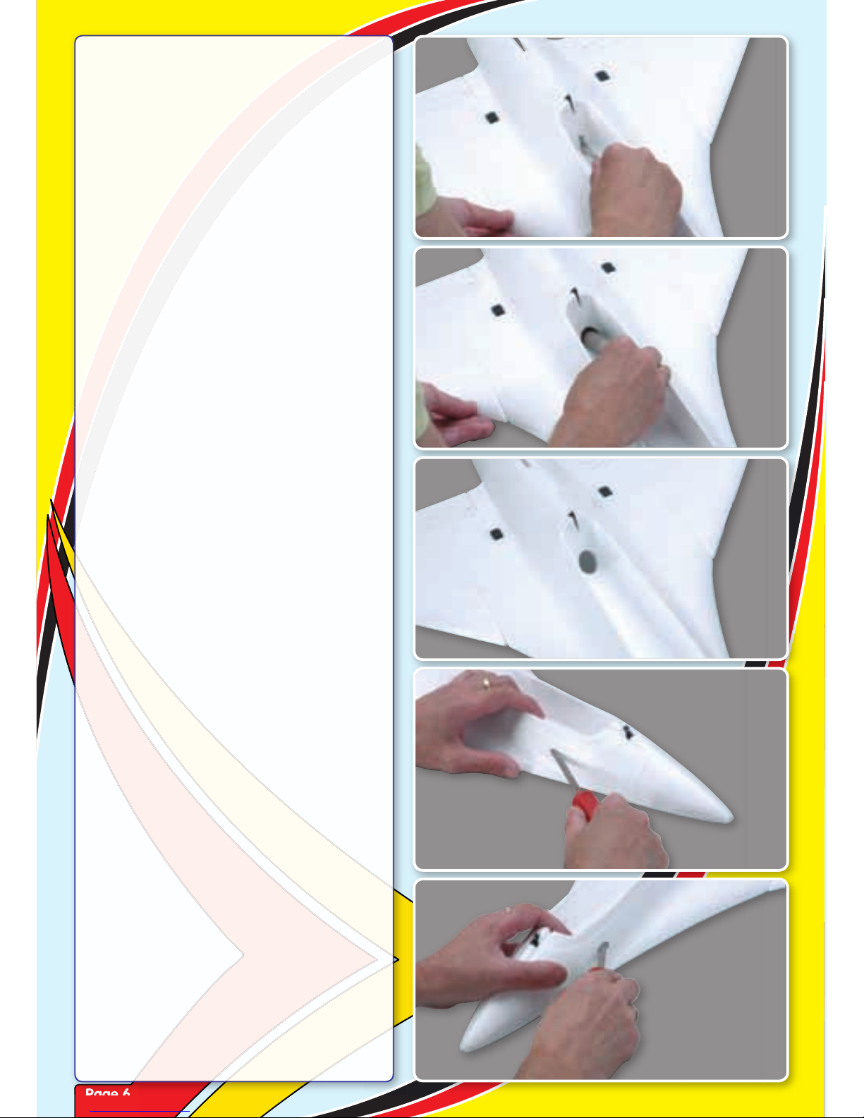
Step 11
To ensure adequate battery cooling, we
recommend opening up an air exit from
the battery bay into the duct.
Step 12
Using a large round file or Permagrit tool
as shown here, continue to open up the air
exit.
Step 13
An exit hole of approximately 30mm
diameter will ensure adequate cooling air
is drawn over the battery during high load
conditions.
Step 14
To allow cooling air in, we recommend
making two entry holes in the front of the
fuselage as shown.
Step 15
Make the second hole on the other side of
the fuselage in the same position.
Page 7
Page 7
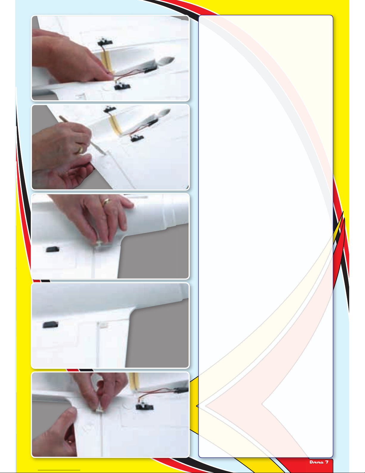
Step 16
Use a couple of strips of masking tape
to retain the elevon servo leads in their
respective slots.
Step 17
Prior to fitting the control horns, trim away
the clear hinging tape from the slots in the
elevon.
Step 18
Locate a control horn and insert from the
top side of elevon. Note that the horn is
orientated forwards.
Step 19
Push the horn down into place ensuring
that it is flush with the top surface of the
elevon.
Step 20
Slide an elevon horn retaining plate over
the horn, noting its orientation.
Page 8
Page 8
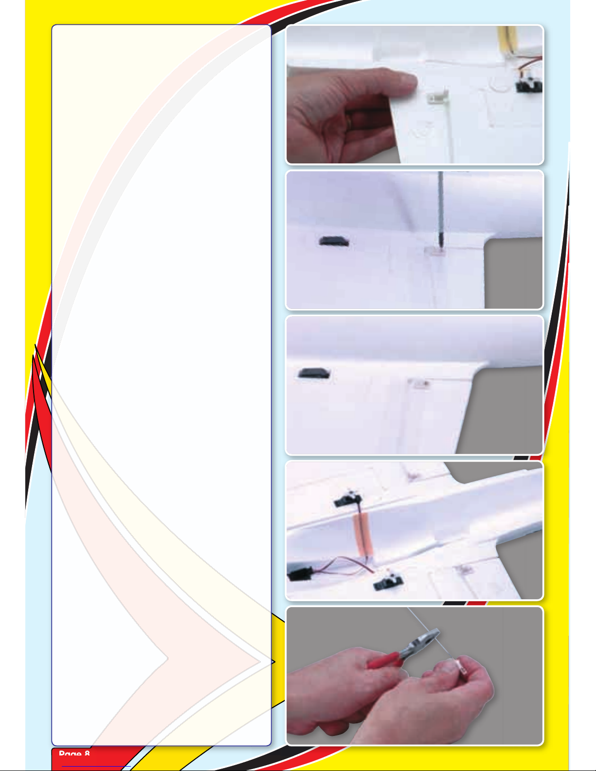
Step 21
Squeeze the two parts together until
the bottom of the horn is flush with the
underside of the elevon.
Step 22
Locate a control horn self tapping screw
and install through the top of the horn and
into the retaining plate.
Step 23
Do not over tighten the retaining screw you do not want to crush the elevon.
Step 24
Fit the second elevon horn using the same
procedure.
Step 25
Locate a moulded clevis and threaded
pushrod. Screw the clevis onto the rod until
the thread is just visible through the clevis.
Page 9
Page 9
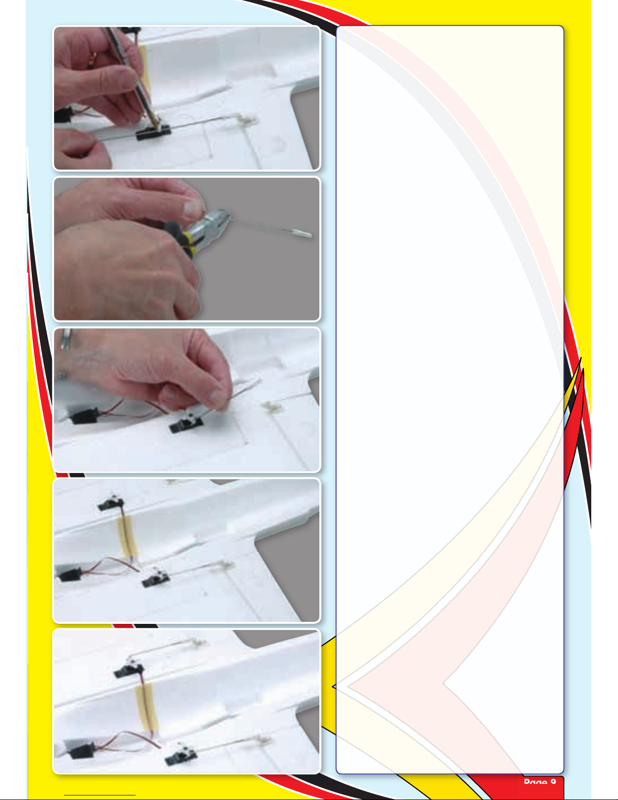
Step 26
Ensuring the servo and elevon are centred,
fit the clevis in its horn and mark the
position the pushrod crosses the outer hole
in the servo horn.
Step 27
Form a z-bend at the marked point and cut
off the excess pushrod wire as shown.
Step 28
Connect the prepared z-bend to the servo
horn’s outermost hole. This should be
approximately 10mm out from the servo’s
centre.
Step 29
Adjust the pushrod’s length by screwing the
clevis in or out until the elevon is centred.
Now push the clevis into the control horn
until it clicks.
Step 30
Complete the second elevon linkage using
the same procedure above.
Page 10
Page 10
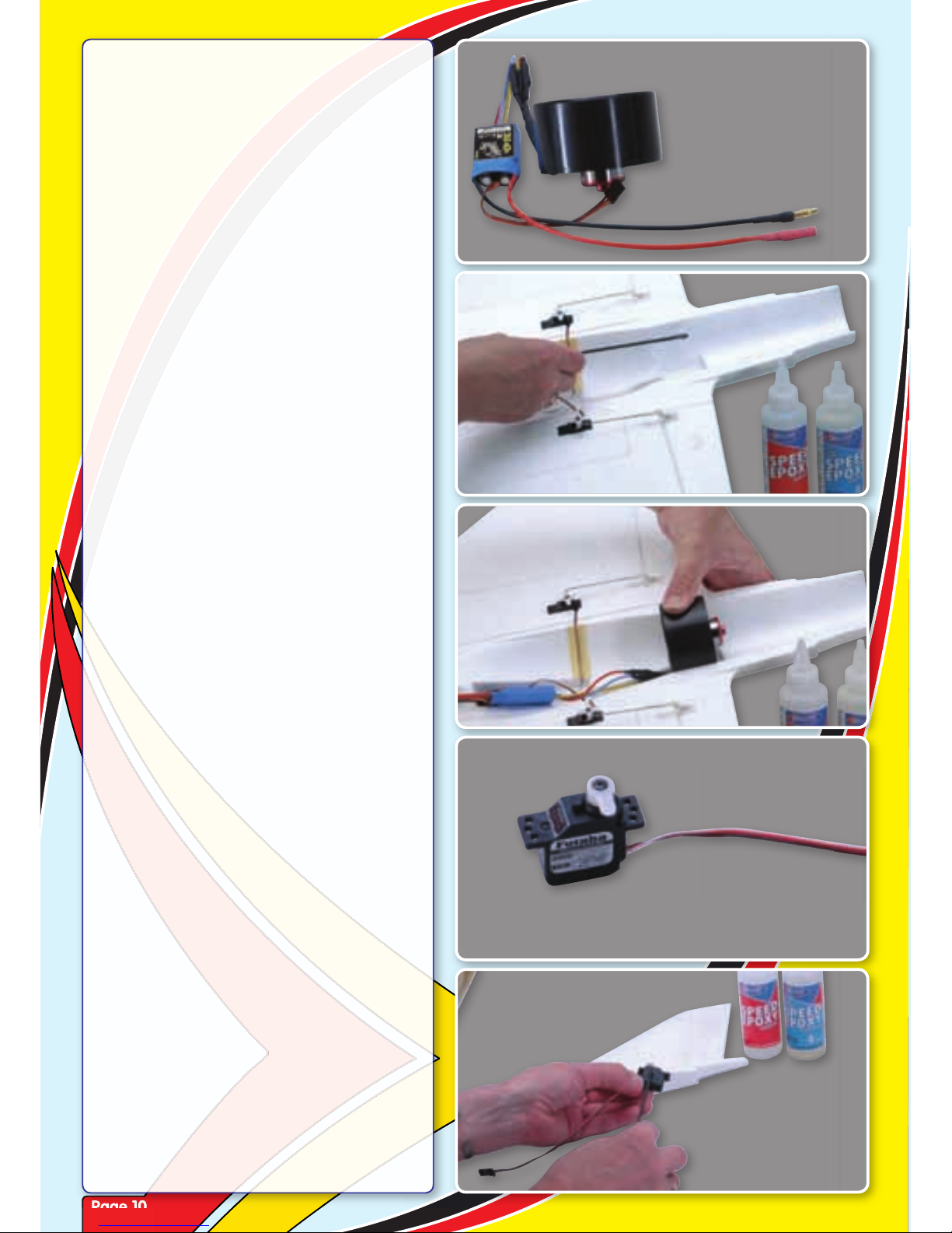
Step 31
Prepare the ESC by soldering on your choice
of connectors. We recommend 4mm gold
bullet connectors. Ensure the polarity is
correct.
Step 32
Test fit the fan unit, noting the wires fit in
the moulded channel under the fin mount.
Apply epoxy sparingly as you may wish to
remove the fan unit at some point in the
future.
Step 33
Glue the fan unit in position making sure
none of the wires are trapped. Hold in
place until the epoxy cures.
Step 34
Prepare your rudder servo’s control horn as
shown. Centre the servo.
Step 35
Check the fit of your servo in the moulded
recess and trim the foam if necessary. Apply
a small quantity of epoxy to the servo.
Page 11
Page 11
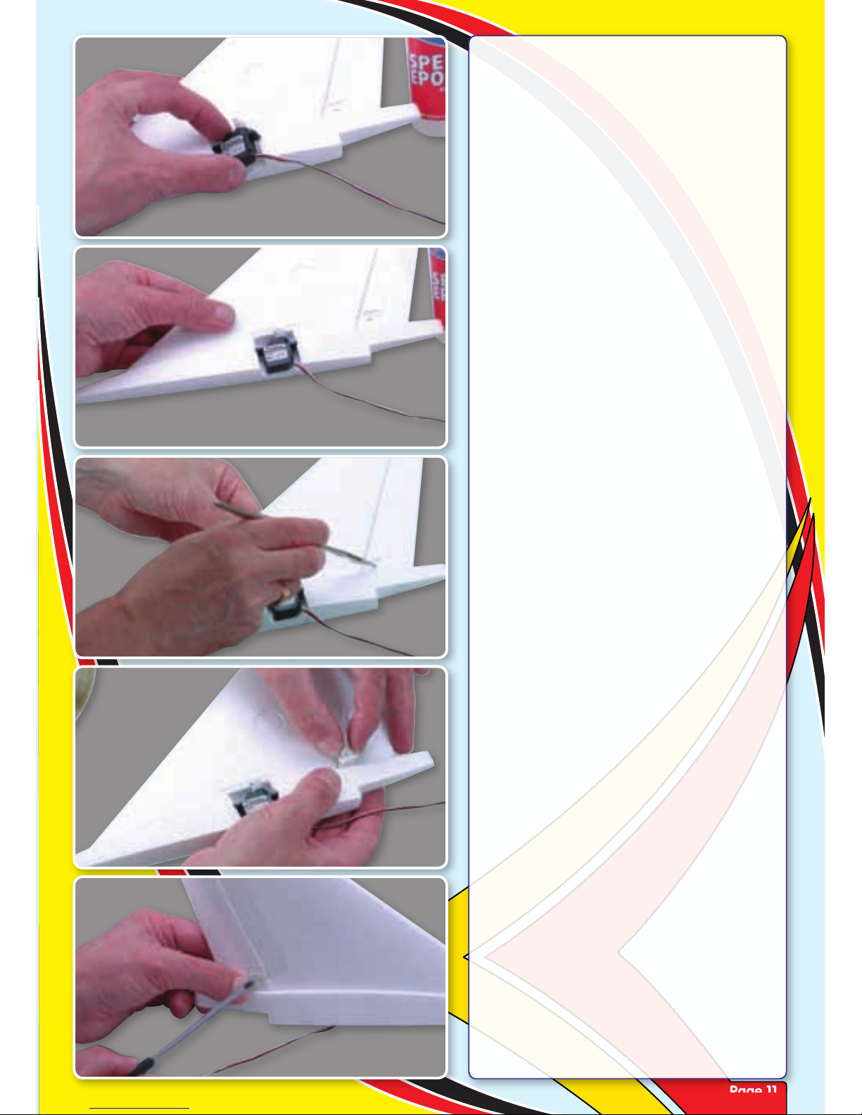
Step 36
Glue the servo in position noting its
orientation with the servo horn to the rear
of the fin.
Step 37
Ensure the base of the servo does not
protrude below the base of the fin.
Step 38
Before fitting the rudder control horn, trim
away the clear hinging tape from the slot
in the rudder.
Step 39
Fit a control horn through the rudder and
fit a retaining plate in the same way as the
elevon control horns were fitted.
Step 40
Complete the installation of the horn by
installing a self tapping screw through the
control horn and into the retaining plate.
Page 12

Page 12
Step 41
Prepare a rudder pushrod by screwing a
clevis onto the rod until the thread is just
visible through the clevis.
Step 42
Centre the rudder servo and the rudder. Fit
the clevis in its horn and mark the position
the pushrod crosses the hole in the servo
horn one in from the outermost.
Step 43
Form a z-bend at the marked point and cut
off the excess pushrod wire as shown.
Step 44
Adjust the pushrod’s length by screwing the
clevis in or out until the rudder is centred.
Now push the clevis into the control horn
until it clicks.
Step 45
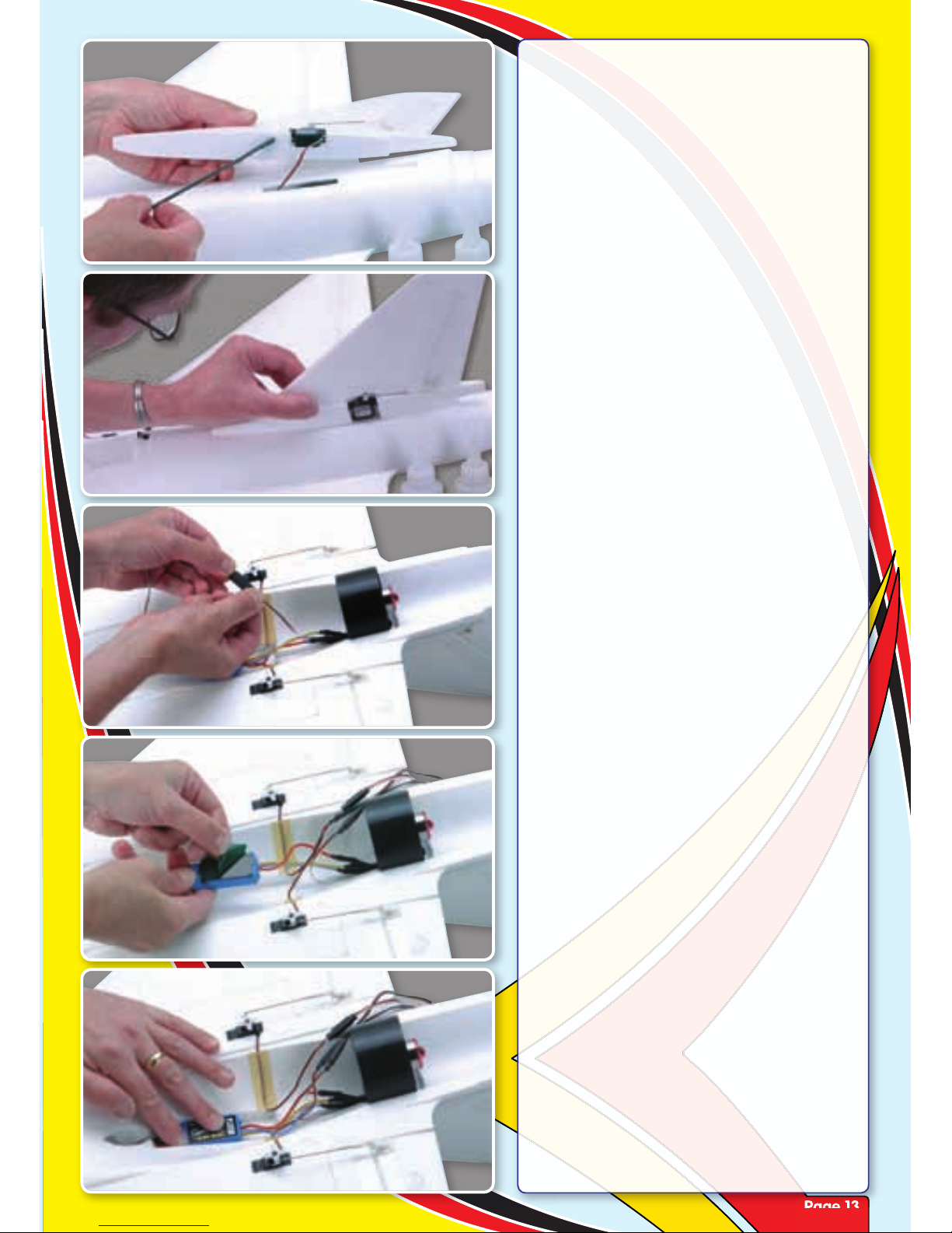
Thread the rudder servo lead though the
opening in the top of the fuselage and
ensure that the motor leads are pushed
down into their recess.
Page 13
Page 13
Step 46
Mix up some epoxy and thoroughly cover
the base of the fin taking care not to get
epoxy on the servo or motor leads.
Step 47
Pulling the rudder servo lead down into the
duct, glue the fin in position ensuring that it
is square and perpendicular to the wing.
Step 48
Once the epoxy has cured, turn the model
over and attach a 300mm extension lead
to the rudder servo.
Step 49
Attach a length of double sided tape or
Velcro (hook and loop) to the electronic
speed controller.
Step 50
Secure the speed controller in its moulded
recess in the fuselage duct as shown.
Page 14
Page 14
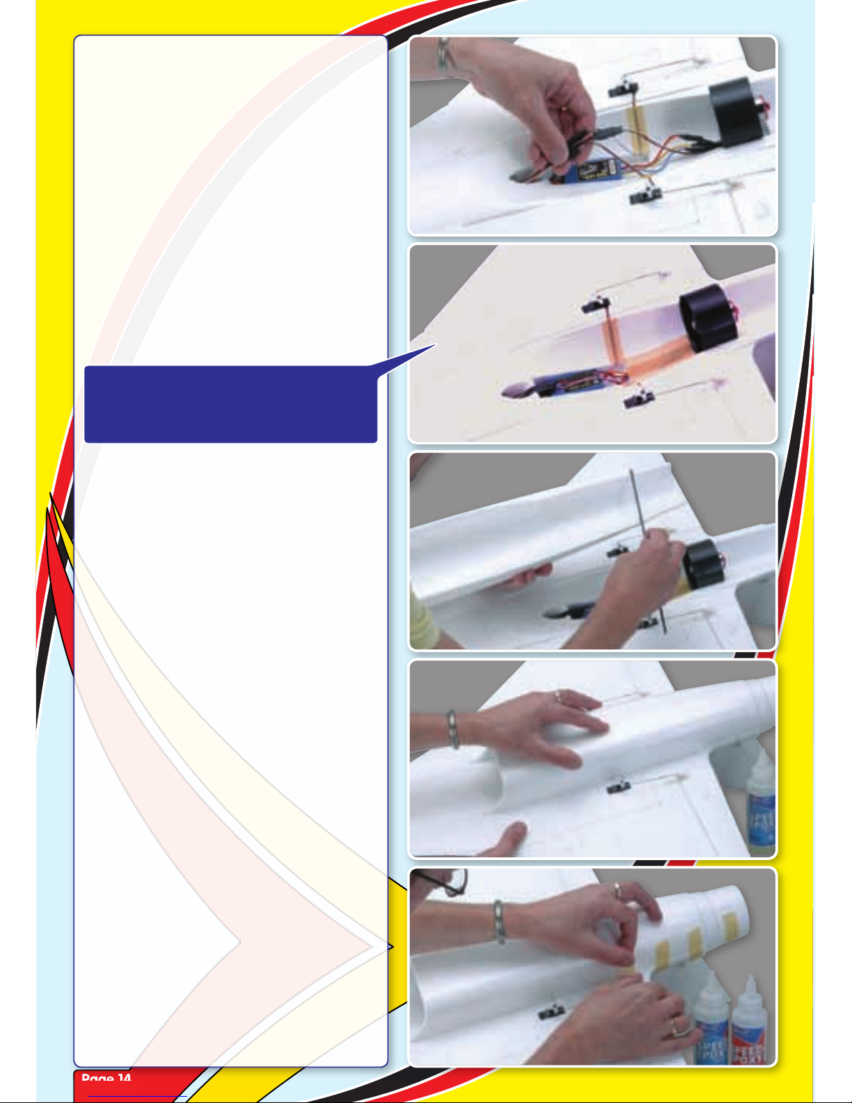
Step 51
Feed the servo extension leads through the
air exit hole and into the radio bay.
Step 52
Hold all leads in place in the duct using
clear tape or masking tape. Do not allow
leads to remain loose in the duct as there is
a risk they will be drawn into the fan.
Step 53
Mix up sufficient rapid epoxy and coat the
bottom of the lower cowl and sparingly
apply epoxy to the fan unit recess to secure
the fan unit to the cowl.
Step 54
Glue the lower cowl in position making sure
it is firmly pressed into its recessed slots.
Ensure that the rear of the cowl is aligned
with the rear of the fuselage.
Step 55
Use small strips of masking tape to
accurately hold the cowl in position as the
epoxy cures.
SEE PAGE 25 - SETTING UP THE ESC
YOU CAN NOW TEST THE ESC AND FAN
UNIT. ENSURE THE FAN ROTATES ANTICLOCKWISE VIEWED FROM THE FRONT.
Page 15
Page 15
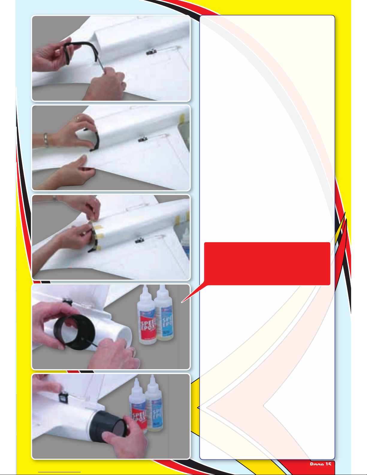
Step 56
Now apply epoxy to the inside of the prepainted, moulded intake lip as shown.
Step 57
Glue the intake lip moulding in position
making sure that any excess epoxy that
squeezes out is wiped off.
Step 58
Use small strips of masking tape to ensure
the moulded intake lip is held tightly to the
cowl as the epoxy cures.
Step 59
Mix up a small amount of epoxy and apply
to the inside of the moulded tailpipe.
Step 60
Slide the tailpipe in position and apply a
couple of strips of tape to secure it while
the epoxy cures.
IMPORTANT: IF YOU PLAN TO FIT THE
OPTIONAL VECTORED THRUST UNIT
DESCRIBED AT THE END OF THIS MANUAL
- PLEASE OMIT STEP 59 AND 60 AND DO
NOT FIT THE MOULDED TAILPIPE.
Page 16
Page 16
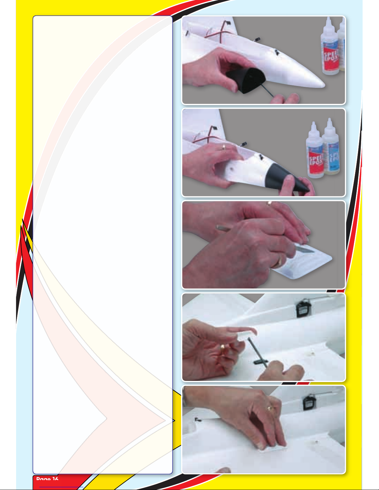
Step 61
Apply more epoxy to the inside of the
moulded nosecone.
Step 62
Slide the nosecone in position. Wipe off any
excess epoxy that squeezes out.
Step 63
Locate the servo cover mouldings. Trim
them with a sharp knife using the moulded
lines as a guide.
Step 64
Apply a tiny smear around the perimeter
of the first elevon servo cover. Do not apply
too much adhesive.
Step 65
Glue the cover in position and hold or
apply a small strip of masking tape while
the epoxy cures.
Page 17
Page 17
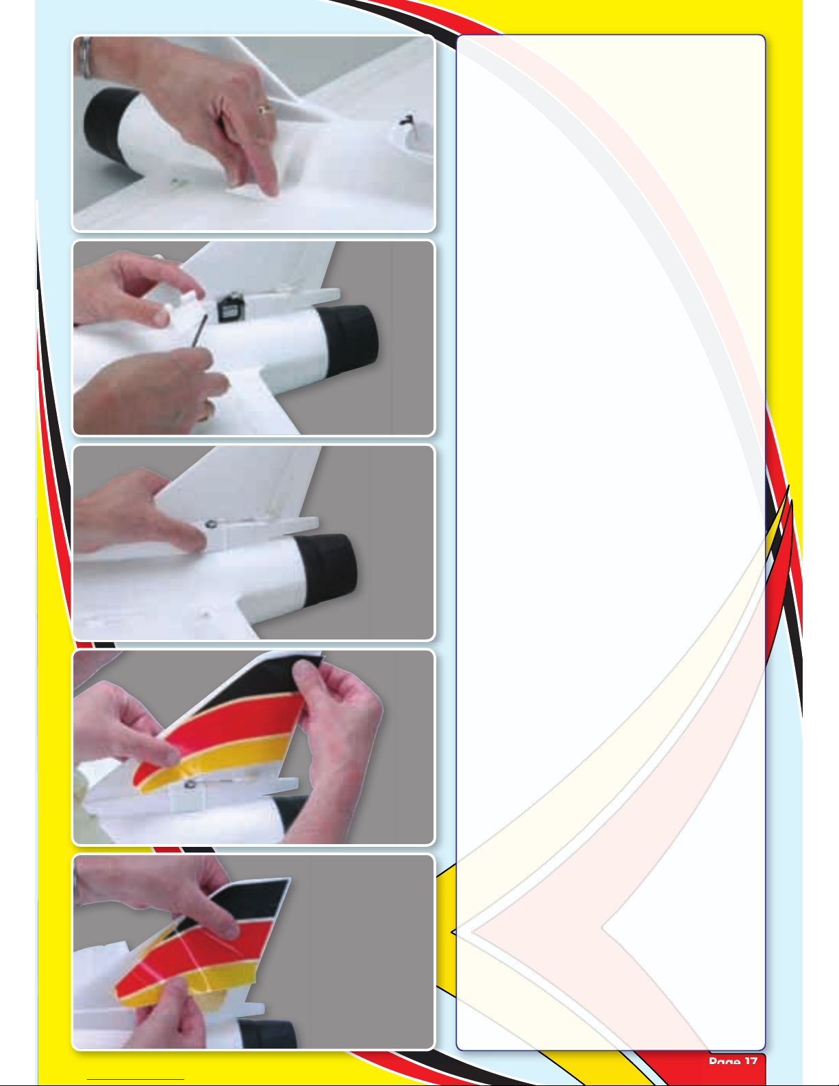
Step 66
Repeat for the second elevon servo cover.
Step 67
Carefully trim the rudder servo cover to
clear the output horn. Now apply a smear
of epoxy to the perimeter of the cover.
Step 68
Glue the cover in position and hold or
apply a small strip of masking tape while
the epoxy cures.
Step 69
Trim the decals from decal sheet leaving a
small perimeter of clear around each.
Remove just one corner of the backing
paper and position the decal correctly.
Step 70
Carefully remove the remaining backing
paper while rubbing down the decal. Work
slowly to avoid any wrinkles.
Page 18
Page 18
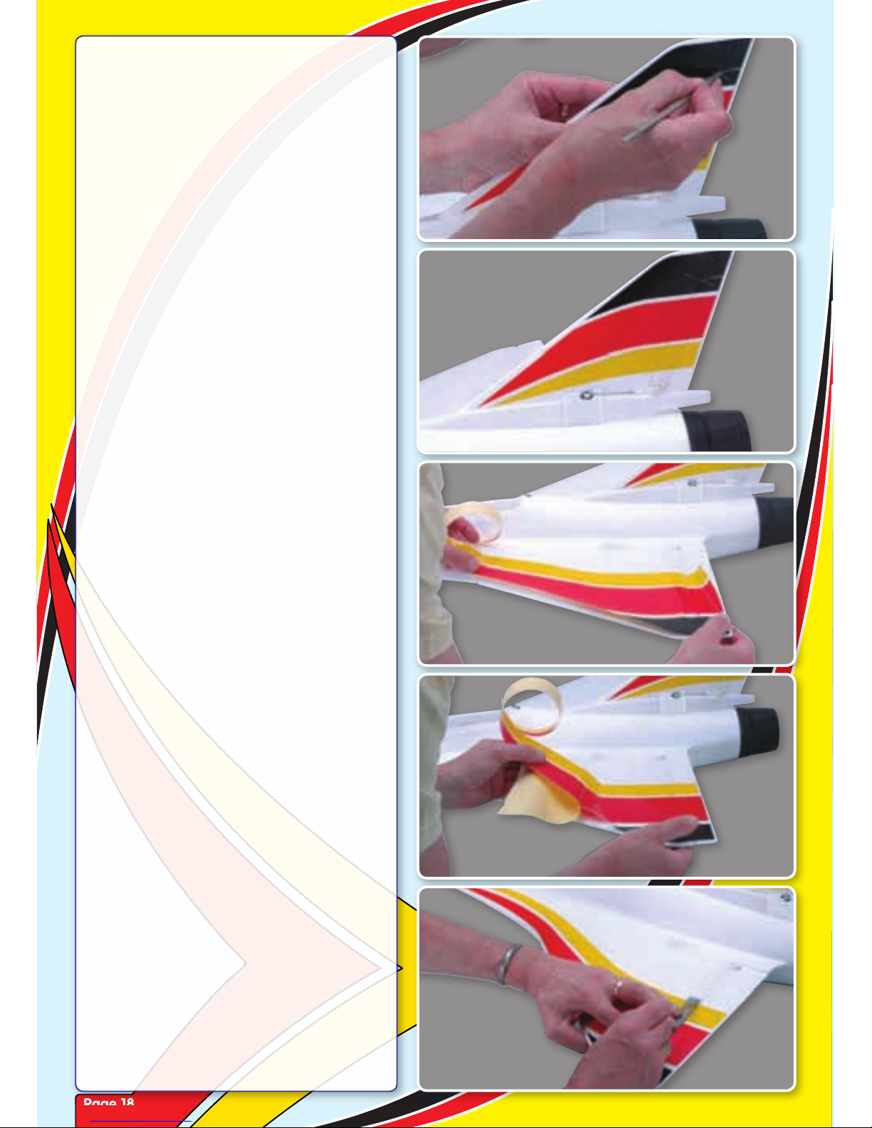
Step 71
Once applied, carefully cut through the
decal where the rudder separates from the
fin.
Step 72
Ensure that you don’t cut the hinge tape,
run a sharp knife through the decal when
the rudder hinges.
Step 73
Apply the main wing decal in the same
way buy only removing a corner of backing
paper to start with.
Step 74
Carefully remove the remaining backing
paper while rubbing down the decal. Work
slowly to avoid any wrinkles.
Step 75
Using a ruler and sharp knife, run a sharp
knife through the decal when the elevon
hinges. Work carefully to ensure that you
don’t cut the hinge tape.
Page 19
Page 19
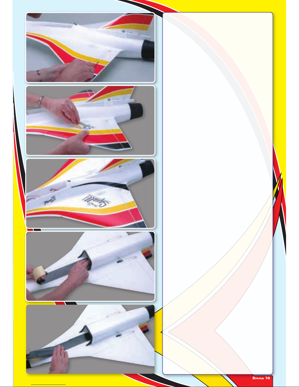
Step 76
Use the back of your knife to smooth the
cut decal down into the hinge line.
Step 77
Apply the decals to the other wing panel
and fin. Now add the all-important Squall!
decal.
Step 78
Just the Phase 3 decals to add to each side
of the fuselage and the top of the model is
complete.
Step 79
Turn the model over and apply the longer
black strip to the front of the model. Apply
the end of the decal in the duct (just in front
of the air exit hole
Step 80
Work forward to the nose, carefully
removing the backing paper and rubbing
down the decal as you go.
Page 20
Page 20
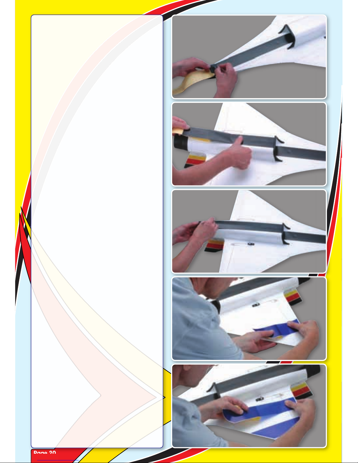
Step 81
Use a sharp knife to trim the decal flush
with the moulded nosecone.
Step 82
Starting from the intake lip, apply the
second black decal to the underside of the
cowl.
Step 83
Trim the rear of the decal flush with the
moulded tailpipe using a sharp knife.
Step 84
The underwing decals are best applied
singly, but you can mark their positions
with a pencil before separating them from
the decal sheet.
Step 85
Apply the second stripe ensuring that it
remains parallel to the first or use the pencil
guide marks you made. Rub down the
decal as you remove the backing paper.
Page 21
Page 21
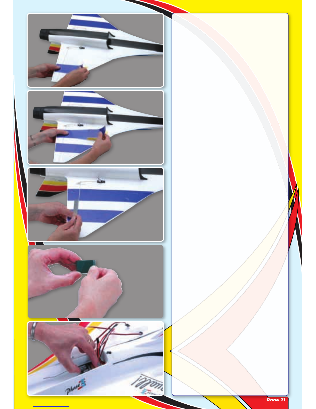
Step 86
Repeat the for the second wing panel
working from from the trailing to leading
edge.
Step 87
The final stripe is applied in the same way
with the backing paper removed carefully
as you work your way to the leading
edge.
Step 88
Again, using a ruler and sharp knife, run
through the decal when the elevon hinges
working carefully to ensure that you don’t
cut the hinge tape. Use the back of your
knife to smooth the cut decal down into the
hinge line.
Step 89
Apply a strip of double sided tape or
Velcro (hook and loop) to the rear of your
receiver.
Step 90
Attach the receiver to the base of the
fuselage towards the rear of the radio
bay.
Page 22
Page 22
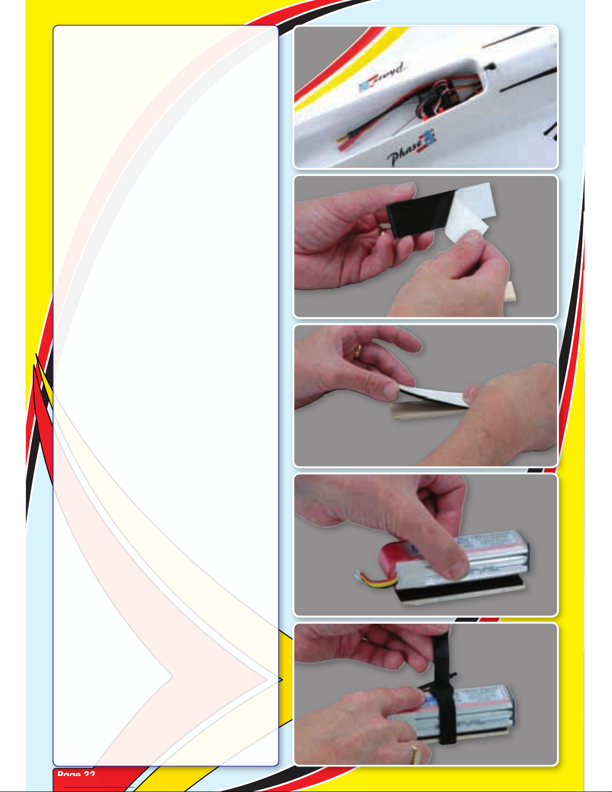
Step 91
Connect the two elevons, rudder and ESC’s
throttle lead to the appropriate receiver
channel outputs and tidy the wiring with
cable ties.
Step 92
Prepare the Li-Po battery mount by
removing the backing paper from the
Velcro (hook and loop) supplied.
Step 93
Attach it to the balsa battery mount,
pressing it firmly in position.
Step 94
Remove the second backing paper and
attach your Li-Po to the Velcro as shown.
Step 95
Use the supplied Velcro strap to give an
additional level of security to the battery
retention. This is a highly aerobatic model
and you don’t want to lose the battery in
flight!
Page 23
Page 23
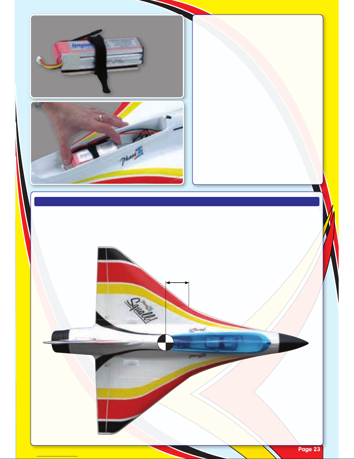
Step 96
Ensure that the Velcro retaining strap is
orientated as shown as it is glued into the
model with the tray in this position.
Step 97
Place the battery on its tray into the radio
bay.Temporarily fit the canopy and test the
balance point as shown below.
BALANCE POINT (C/G)
The Squall! should balance at a point 60mm back from the leading edge where the wings meet the
fuselage. The Squall! must be correctly balanced before flying. The aircraft should sit level or slightly
nose down when you support it on a balancer or with your finger tips at the balance point. Move the
Li-Po battery on its tray forwards or backwards until the model balances correctly.
60mm
C
G
Page 24
Page 24
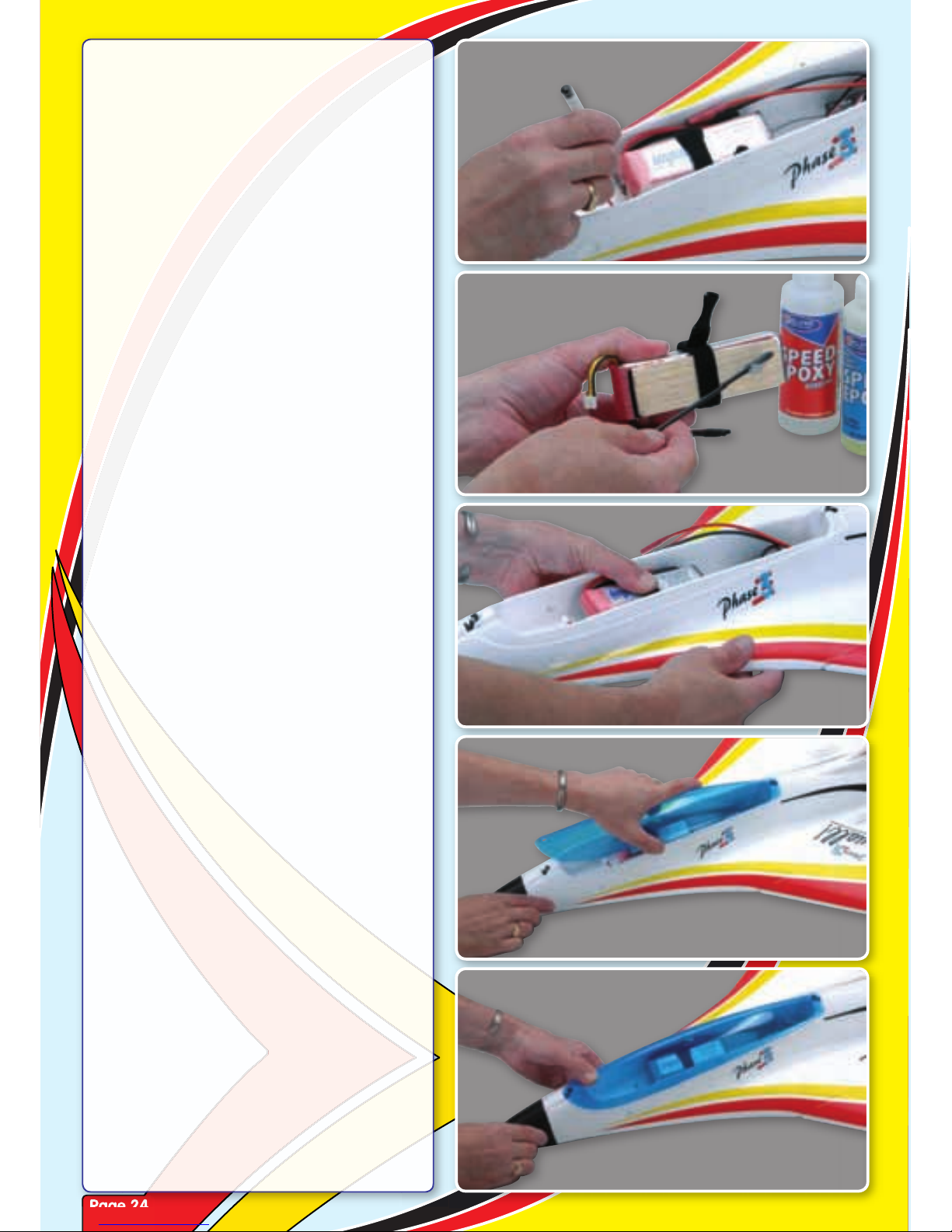
Step 98
Now remove the canopy and carefully
mark the position of the tray.
Step 99
Use plenty of epoxy to attach the battery
tray to the base of the fuselage in this
position in the radio bay.
Step 100
Hold the battery in position while the epoxy
cures. The battery can now be removed for
charging by releasing the Velcro strap.
Step 101
The canopy is supplied factory trimmed and
ready to fit. Simply locate the rear ‘W’ latch
in its cutout in the rear of the canopy.
Step 102
Keeping the canopy pulled forward, slip the
front ‘W’ catch in the cutout in the front of
the canopy and allow it to snap into place.
Pushing the front canopy catch towards
the rear allows the canopy to be removed.
Page 25
Page 25
Step 103
The Squall! is complete. Now set-up the
control throws as shown below.
CONTROL THROWS
The Squall! is complete. Now set-up the
All control throws are measured at the control surfaces widest point and each is measured from
neutral. Begin with the ‘Normal’ throws and safe centre of gravity position. Experienced flyers can
increase the throws to the ‘Highly Aerobatic’ once they are happy flying the model.
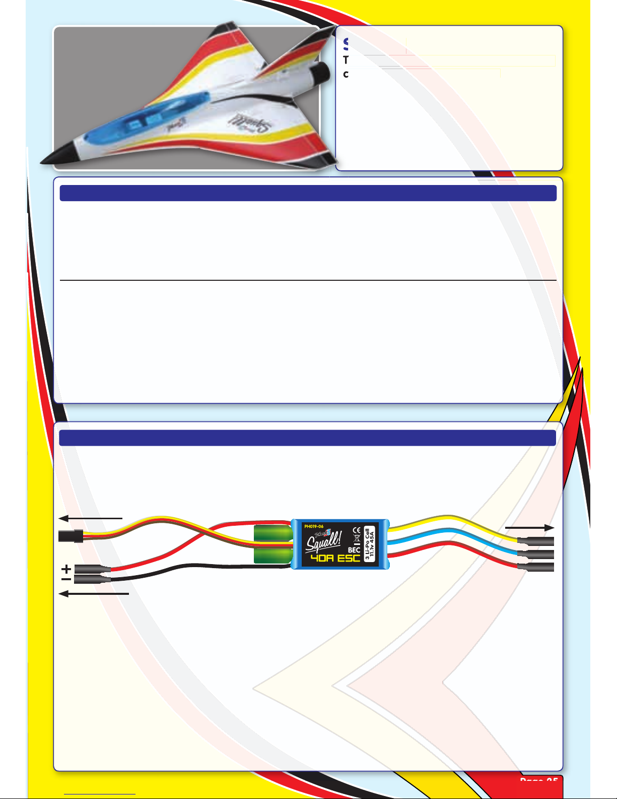
SETTING UP THE ESC
The Squall! is supplied with an electronic speed controller (ESC) that is very simple to set up. It is
connected as shown in the diagram here.
If you are using a Futaba transmitter, reverse the throttle channel. If you are using a JR transmitter,
leave the throttle channel in its normal position. If your are using a different transmitter, refer to the
user’s guide provided with your radio control system. In all cases, set the throttle ATV (Adjustable
Travel Volume) set at 120% on full throttle.
With the throttle control stick at its LOW position, switch on the transmitter. Connect a fully-charged
LiPO battery. There is no separate switch, so connecting the Li-PO battery will turn on the airborne
radio components and begin the motor arming process.
The ESC emits three short ‘beeps’ to confirm that it is armed. Now slowly move the throttle control
stick and the fan will spin.
Elevator 12mm Up/Down ....................20% Expo
Aileron 12mm Up/Down ....................20% Expo
Rudder 10mm Left/Right ....................20% Expo
Safe CG is 60mm from leading edge of the outer
wing panel.
Elevator 22mm Up/Down ...................40% Expo
Aileron 22mm Up/Down ...................40% Expo
Rudder 16mm Left/Right ....................25% Expo
Aerobatic CG is up to 70mm from leading edge
of the outer wing panel.
NORMAL THROWS: HIGHLY AEROBATIC THROWS:
Do not attempt to test fly the model with the Highly Aerobatic throws or CG position!
To Motor
To Flight Battery
To Receiver
Throttle Channel
Page 26

SPARE PARTS LIST
PH019-01 Airframe Parts - All Squall!
PH019-02 Canopy (Blue) - All Squall!
PH019-03 Decal Sheet - All Squall!
PH019-04 Linkage Set - All Squall!
PH019-05 ESC 40A (11.1v) - Squall!
PH019-06 ESC 45A HP (14.8v) - Squall! HP
PH019-07 Motor 3800kv (11.1v) - Squall!
PH019-08 Motor 3400kv (14.8v) - Squall! HP
PH019-09 Fan Unit (No Impeller) - All Squall!
PH019-10 Fan Impeller-3 Blade - Squall! HP
PH019-11 Fan Impeller-5 Blade - Squall!
PH019-12 Fan Adaptor - All Squall!
PH019-13 Vectored Thrust Unit - All Squall!
PH019-14 Vectored Linkage Set - Squall!
Page 27
FLYING THE SQUALL
OUR GUARANTEE
Phase 3 Models guarantees this kit to be free from defects in both material and workmanship, at the date of purchase. This
does not cover any component parts damaged by use, misuse or modification. in no case shall Phase 3 Model’s liability
exceed the original cost of the purchased kit.
In that Phase 3 Models has no control over the final assembly or material used for final assembly, no liability shall be
assumed for any damage resulting from the use by the user of the final user-assembled product. By the act of using the final
user-assembled product, the user accepts all resulting liability.
Always turn on the transmitter before connecting the Li-Po battery. Ensure the throttle stick is at
its low position. Connect the Li-Po battery and check that all control surfaces deflect in the correct
direction when the sticks are moved. Ensure the model balances correctly and that the control throws
are correct.
Perform a range check. While the Squall! is very easy to hand launch on your own we recommend
that you ask a friend to help for the first flight so you can concentrate on trimming. Grip the model by
the fuselage under cowl. Test the motor by pushing the throttle fully open then pull it fully back.
If there is any wind, get your helper to turn and face directly into it. Open the throttle and have model
launched from shoulder height with a firm, level push. The model will accelerate quickly. Allow it to
gain speed in straight and level flight.
The Squall! is a high performance jet that yields its best performance when flown smoothly. It is
perfect for high speed beat-ups and large open aerobatics. The Squall! HP on 4 cell packs is in its
element when being wrung out through extreme manoeuvres. With a quality battery, the vertical
performance is limitless as it will have a greater than 1:1 thrust to weight ratio.
After landing, unplug and remove the battery from the model and allow it to cool completely before
recharging it for your next flight.
REPAIRING THE SQUALL
Most damage can be repaired quickly and easily. If the damage is beyond repair, spare parts are
available for purchase. If a foam part is going to break during a crash it will usually break cleanly. To
repair a clean break, follow the procedures below:
• Glue the broken parts together, using a thin layer of 5 minute epoxy or white glue. Hold the parts
together and in alignment until the glue fully cures.
• Apply a strip of clear tape over the seams to strengthen the joint even more.
WARNING It is very important that you use no solvents or Cyanoacrylate (C/A) glue, which can damage
foam. If any of these chemicals comes in contact with the foam parts, the parts will be destroyed. Use
only epoxy or white glue to repair damaged foam parts.
 Loading...