

Page 1
1
TOCR02
2 PART MICRO MOTION
SENSOR W/IR REMOTE
CONTROLLER
Power Circuit Part
PIR Motion Sensor
INTRODUCTION
The use of occupancy detectors in commercial and
industrial applications can significantly reduce energy
usage reducing both energy costs and helping the
environment.
The Titan 360 degrees MICROSENSITIVE 2 PART
flush mount OCCUPANCY DETECTOR uses passive
infrared sensors (PIR) which react to changes in
temperature emitted by the slight motion of persons or
objects passing through its detection area. The PIR
sensor automatically operates the connected load
when an area is occupied. After a preset time on
non-activation (when an area is vacated) the load will
be switched off. In addition the built in photocell takes
natural light (daylight) into account when determining
its activation..
It also incorporates lux memory feature which means
the sensor is able to record and memorize the lux
level when the internal connected light fixture is turned
on by the Micro Motion Sensor. However, once the
natural light lux level is higher than that of the internal
artificial light even if the movement still exists, the
sensor will switch off the internal light fixture thus
saving energy.
The product also incorporates a 2 part structure
allowing the initial installation to be made and the
detector removed to avoid damage during painting,
maintenance etc.
The product is also supplied with a two channel Infra
Red remote control for remote operation.
Note: Read this entire manual before you start to
install the system.
SAFETY PRECAUTIONS
Be sure to switch off power source before
installing.
Make sure that the power wiring comes from
circuit with an external 16A miniature circuit
breaker for the short circuit protection or a
suitable fuse.
The unit is designed to be mounted on the
ceiling.
(FIGURE 1)
FIGURE 1
The installation of this device should be made by
a qualified electrician.
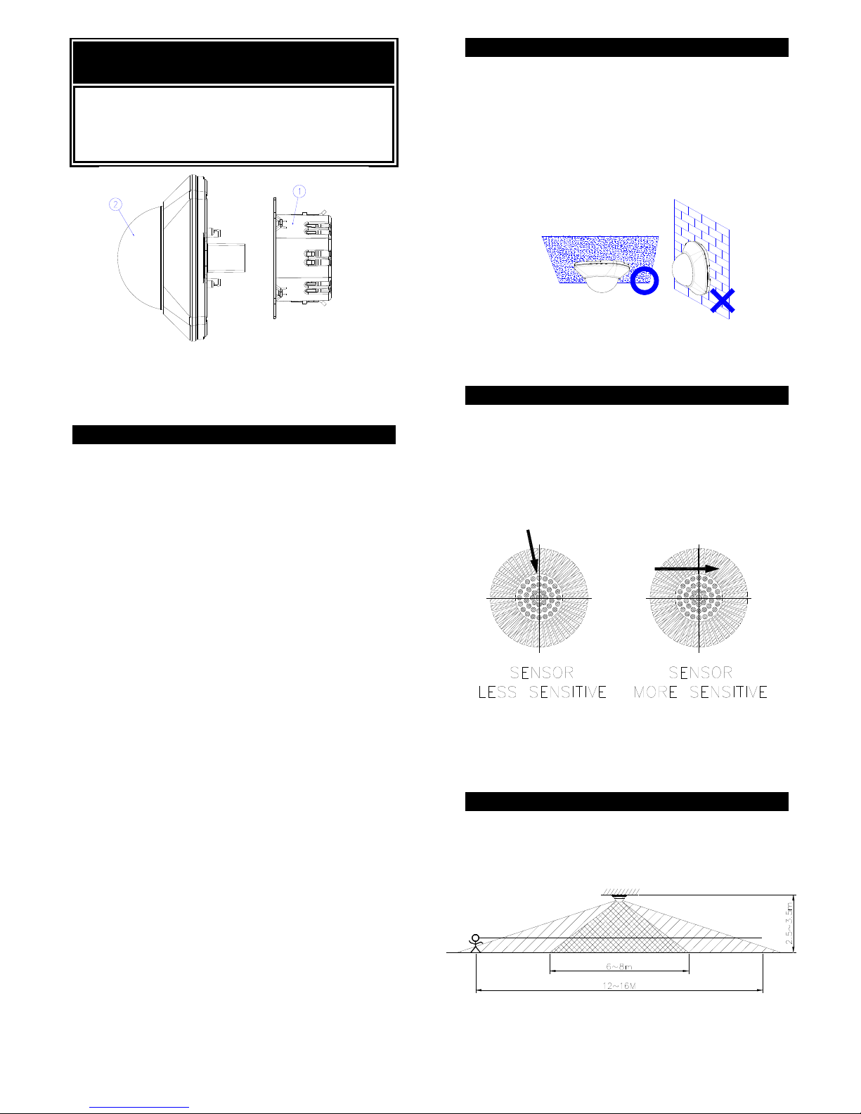
CHOOSING A MOUNTING LOCATION
Avoid aiming the motion sensor at heating vents,
air conditioners or objects which may change
temperature rapidly.
Prior to mounting the light fixture, remember to
position the motion sensor so that a moving
object cuts “across” its beams, not directly
towards them.” (FIGURE 2)
FIGURE 2
Note: Micro motion detection can be made within
a radius of 3m around the sensor; regular motion
detection can be made within a radius of 6m
around the sensor.
INSTALLATION
A drill and a screwdriver are needed for installation.
Select a location for the unit based on the coverage
angles shown in FIGURE 3.
Page 2
2
FIGURE 3
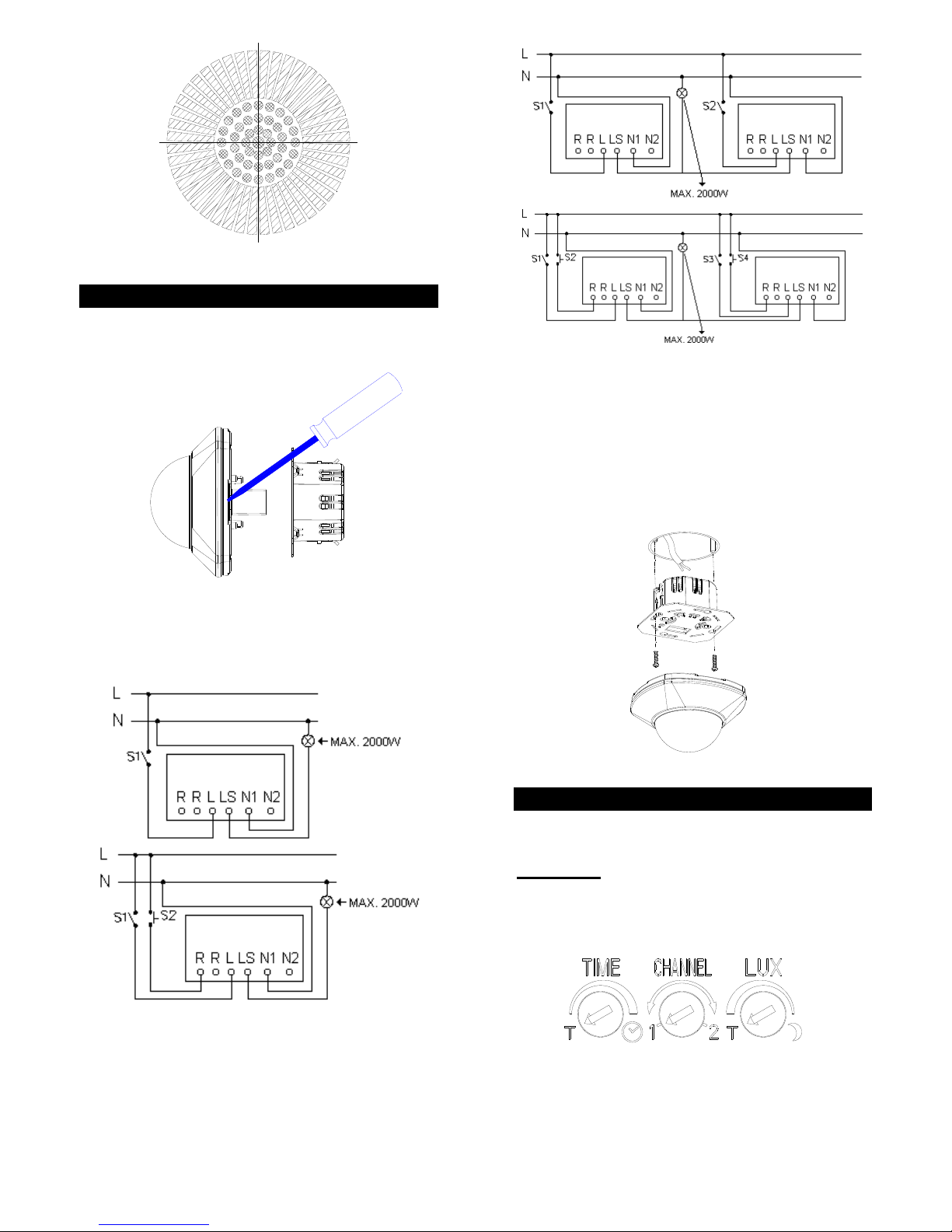
WIRING INSTRUCTION
(1) Switch off the power source or wall switch.
(2) Using a flat blade screwdriver to detach the PIR
motion sensor and power circuit part. (FIGURE
4)
FIGURE 4
(3) When connecting to one Micro Motion Sensor, the
wiring connection is shown hereunder: (FIGURE
5a)
FIGURE 5a
By connecting to two Micro Motion Sensors, the wiring
connection is indicated as below: (FIGURE 5b)
FIGURE 5b
Note: A pulse switch (S2,S4) is connectable to the
unit, enabling manual operation.
(4) A 60mm hole should be drilled in the ceiling, put
the power circuit to the hole and secure it using to
the mounting surface using the screws provided.
Fix the PIR motion sensor to the power circuit part
by simply clicking in place (FIGURE 6).
FIGURE 6
SETTING THE LIGHTING SYSTEM
Please test the motion sensor function before testing
the IR Remote Controller.
Test Mode :
Turn the LUX control and the TIME control anti
clockwise – the TEST position. (FIGURE 7)
FIGURE 7
Turn on the wall switch. The light will turn on for
about one minute to warm up. During warm-up
Page 3

3
period, the light turns on continuously. After one
minute is expired, the light will turn off.
Walk through the detection area, the light will turn
on continuously. If and when movement is
ceased, the light will be on for one second before
turning off.
(1) TIME ADJUSTMENT
The TIME adjustment controls how long the light will
stay on after the last motion has been detected. Time
setting is adjustable from 5 seconds to 12 minutes.
(FIGURE 8)
ABOUT 5 SECONDS ABOUT 12 MINUTES
FIGURE 8
Note: T serves as a short-time impulse, which allows
you to control automatic switching of staircase lighting
or timer.
(2) LUX ADJUSTMENT
The LUX adjustment determines at what light level the
lighting system will start operating when you set the
sensor to automatic operation.
Provisionally turn the LUX control knob clockwise to
the moon (dusk) position (FIGURE 9). Turn the LUX
control knob slowly anti-clockwise until the light comes
on. In this provisional setting mode, the motion
sensor remains inactive during daylight. At dusk
when you find it is the LUX level desired for operation,
simply set the LUX control knob to the position which
becomes active as daylight declines. The light turns
on when you move and turns off when you stop.
Wait for the light to turn off before moving again to test
the sensor.
FIGURE 9
(3) CHANNEL SELECTION
To avoid radio signal interference, and operate
separate banks of detectors on a single remote, you
are able to select different channels through channel
switch. Select channel 1 or 2 on the sensor for
grouping the connected light fixtures in the same or
different zone.
E253R IR Remote Controller
2
3
1
4
FIGURE 10
3-button and channel selection slide switch are shown
on the front cabinet as follows: (FIGURE 10)
AUTO
ON
OFF
CHANNEL SWITCH
LOADING THE BATTERY
(1) Use a flat blade screwdriver to detach the battery
cover from the cabinet. (FIGURE 11)
FIGURE 11
(2) Insert a 12V alkaline battery to the battery
compartment and refit the battery cover. (FIGURE
12)
Page 4

4
FIGURE 12
OPERATION
By using IR Remote Controller to your NL5703, you
can easily select three modes of operation: automatic,
on and off.
Make sure the Micro Motion Sensor and IR Remote
Controller are set at the same channel. (FIGURE
13a & 13b)
1 2
CH
ON
OFF
CH
AUTO
1 2
ON
OFF
21
AUTO
CH
CH
21
FIGURE 13a & 13b
(1) AUTOMATIC OPERATION
Before operating the IR Remote Controller, please
make sure the sensor is in proper setting for Auto
mode.
The sensor detects motion automatically according to
its time and lux setting.
(2) ON
To keep the light on regardless of motion, you can
press “On” button on the IR Remote Controller. The
light will be continuously on.
The LED inside the sensor will light up when receiving
IR Remote Controller’s signal.
(3) OFF
By pressing “Off” button to deactivate the light from
illumination.
User can also set the motion sensor back to Auto
operation by pressing “Auto” button on the IR Remote
Controller.
(4) MANUAL OPERATION
By using pulse switch to manually control the
connected light fixture to be turned on or off.
If the connected light fixture has been turned on,
simply press the pulse switch to turn off. If and when
it has been turned off, press the pulse switch to turn
on and the connected light fixture will be turned off
automatically according to the time setting.
(5) LUX MEMORY
Under auto mode, the Micro Motion Sensor is
triggered either by movement or by pressing the pulse
switch, the sensor will automatically record and
memorize its initial lux level. When the ambient lux
level is 1.5 times higher than that of initial lux level, the
sensor will switch off the connected light fixture to
save energy.
This feature is valid subject to the TIME setting being
fixed more than one minute. It is irrelevant to lux
adjustment.
SPECIFICATIONS
Power Requirement AC 220 ~ 240V / 50Hz
Operating Load
(maximum)
Max. 2000W Incandescent
or 1500W fluorescent
Up to 210w LED (dimmable
recommended)
Detection Angle Up to 360° at 20°C
Detection Range
(Micro Movement)
3~4m radius at 20°C
Detection Range
(Regular Movement)
6~8m radius at 20°C
Mounting Height Recommended 2.5~3.5m
Ceiling Mount
IR Controller
Channel 1 & 2
Auto / On / Off
IR Controller Range 8M OPEN SPACE
IR Controller Battery 23A 12V
Wall switch control ON/OFF
Pulse switch control ON/OFF
Time Adjustment
Adjustable 5 seconds ~ 12
minutes
Lux Adjustment Yes
Lux Memory Yes
Warm Up Time About 1 min.
Protection Class
II
*Specifications are subject to change without notice.
A501110061R01
Page 5

5
Warning:
Do not dispose of electrical appliances as unsorted
municipal waste, use separate collection facilities.
Contact your local government for information
regarding the collection systems available.
If electrical appliances are disposed of in landfills or
dumps, hazardous substances can leak into the
groundwater and get into the food chain, damaging
your health and well-being.
 Loading...