

Page 1

TK Series frameless motors installation and application
manual
Rel 2.6 doc MA0012.6 ENG
Phase Motion Control
Via Adamoli 461, 16141 Genova Italy
Ph: +39 010 83 51 61
Fax: +39 010 420 67 36
e-mail:
info@phase.eu
http://www.phase.eu
Page 2

2 Phase Motion Control
TABLE OF CONTENTS
TABLE OF CONTENTS ............................................................................................................ 2
Introduction ......................................................................................................................... 3
Safety ................................................................................................................................. 3
General safety instructions .................................................................................................. 3
Electrical risk ..................................................................................................................... 4
Transport and storage conditions............................................................................................. 5
Transport and packaging ..................................................................................................... 5
Unpacking and mounting ..................................................................................................... 5
Storage ............................................................................................................................ 5
Transportation ................................................................................................................... 6
General technical information on TK frameless motors ................................................................ 7
Thin ring, large diameter motors for high torque, low speed (torque motors) ............................ 8
Spindle motors for mills and lathes .................................................................................... 9
Tube motors, small diameter, for multiple spindle units ......................................................... 9
Selection guidelines ............................................................................................................. 10
How to choose the optimal TK motor? ................................................................................. 10
Motor morphology and protections......................................................................................... 13
TKST Stator..................................................................................................................... 13
Type and manufacture of TK motors ................................................................................... 16
Insulation voltage .......................................................................................................... 17
Over temperature protection ........................................................................................... 17
Ground connection......................................................................................................... 18
Standard type and size of output power leads .................................................................... 19
Anti-resonance filter (snubber) ........................................................................................ 19
Motor integration ................................................................................................................ 21
Stator ............................................................................................................................. 21
Rotor .............................................................................................................................. 22
Mounting of the rotor inside the stator ................................................................................. 22
Radial force vs. mounting eccentricity ................................................................................. 24
Check list after integration ................................................................................................. 24
Page 3
3 Phase Motion Control
Introduction
The present document detail the installation, integration and initial mechanical set-up of PHASE
MOTION CONTROL series TK frameless torque motors (henceforth named TK motors). It provides the
customer with the necessary information on how to integrate and operate with TK in his application.
Remark: The liability of PHASE MOTION CONTROL is in all events limited to the functionality of the
motor alone and is limited to its repair or replacement according to the rules agreed in the documente
Condizioni Generali di vendita Phase Motion Control ,
www.phase.eu, which are implicitly accepted
when the motor is purchased.
Frameless motors are just components, however important, of complex systems of which Phase
Motion Control is not aware and not responsible. The Customer or whoever owns or operates the
system must take the responsibility to assess all safety or economical concerns relevant to the
complete system, over and beyond motor replacement, which may stem from any type of motor
failure, and of which Phase Motion Control is unaware and is not and cannot be responsible.
Safety
The user must have read and understood this documentation before carrying out any activity. In case
of unclear information, please contact PHASE MOTION CONTROL.
Handling, installation and maintenance must be done by competent and trained technical personnell
according to IEC 364. Non-compliance with the safety instructions, statutory and technical regulations
may lead to injuries to persons, damage to property and the environment.
General safety instructions
Anyone having active implants (pacemakers) or having any other ferromagnetic
prosthesis is not qualified to work with these kinds of devices, or to approach them.
Keep at safe distance from the motor!
Electronic devices and measuring equipment may be affected or destroyed by strong
magnetic fields. Avoid placing devices with magnetic parts close to computers,
monitors and all magnetic data carriers (e.g. disk, credit cards, audio and videotape,
etc). Because of strong attraction forces, special caution is required in the direct
proximity of the rotor (i.e. under 100 mm). Therefore heavy or wide objects made of
steel of iron must never be brought close to the rotor by free hand. As magnetic forces
are invisible, their effects are generally overlooked close to the rotor.
To cope with any event of an accident while handling the motor, always have at
hand at least two wedges of solid, non-magnetic material (i.e. aluminium) as well as a
non-magnetic hammer (approx. 2-3 Kg). In emergency cases, these tools are for
separating parts magnetically attached to the rotor in order to free caught limbs
(finger, hand, foot).
Page 4

4 Phase Motion Control
Electrical risk
Before installation verify the motor about any damage due transportation and handling, that may
impair electrical safety.
Drive start-up may produce sudden uncontrolled movement. Keep away from all moving parts to
avoid injury!
Do not connect motor to power supply other that specified by PHASE MOTION CONTROL.
A defective power supply may damage the TK assembly.
It is dangerous to interrupt earth or grounding connections. In no way must an earth wire be
disconnected!
Before servicing, make sure that the TK is not powered.
TK motors may have hot surfaces also when the motor is not powered. Normal operating temperature
could be over 100°C.
Slow turning motors have high back-EMF. For example, a TK-xxx-xxx-100 would develop 300 Vac at
its terminals when manually rotated at 5 rpm. Beware of manual or gravitational rotation, dangerous
voltage can be present at the motor terminals even if the machine is not connected.
WARNING: Deep deflux motors (constant power range > 1:2) may deploy higher than mains voltage
between motor and series inductor. Verify maximum interconnection voltage while siziong the plant.
Page 5

5 Phase Motion Control
Transport and storage conditions
Transport and packaging
The PHASE MOTION CONTROL standard package is designed to avoid transport damage.
If any transport damage is observed upon reception of the goods, please inform immediately Phase
Motion Control so that transport damages can be timely claimed or corrected.
Unpacking and mounting
To unpack the TK, please adopt all general safety instructions, reported on the paragraph 3.1.
After opening the package, never pull the motor cable, nor lift the motor by its cables.
Check for cable damage during transport or unpacking
For handling of heavy motors (i.e. >15Kg) the use of lifting tools is recommended, using threaded
lifting bolts, when possible, or using a lift belt.
When storing the motor outside the original packaging put a non-magnetic spacer (i.e. wood) with
40-mm minimum thickness between stator and rotor.
After unpacking the rotor, keep the original rotor wrapping or wrap the magnetic part of the rotor
with paper tape, to keep the magnetic surface clean. The tape must be removed just before mounting
the rotor into the stator.
Take care with the rotors banded with carbon fibre ring: an accidental contact with metallic parts
attracted by the magnetic field can cause damages to the carbon ring, if this happens please contact
PHASE MOTION CONTROL.
Do not leave the rotor outside of its package longer than necessary for assembly to prevent pollution
of the magnet surface and accidents
After mounting verify that the rotation of the rotor inside the stator is free, without contact for the
whole revolution.
Storage
The storage area of TK motors must be strictly restricted and indicated with “Caution, powerful
magnets”.
Motors and motors parts, whenever possible, should be stored in the original packaging.
The storage air humidity should be between 5 and 80% and the temperature between 5 and 45°C.
Should components be stored outside their original packaging, wrapping with oiled paper to prevent
corrosion is recommended.
Magnetic parts should be separated and wrapped in non-magnetic protection. These protections
should be at least 40 mm thick.
Page 6

6 Phase Motion Control
Transportation
By land
The motor must be shipped with original packaging; if it is not possible use IP54 protection
packaging. The parts must be packaged firmly to avoid any movement in case of shocks.
By sea
Use only sea standard packaging (IP55).
By air
CAUTION: if the rotor must be shipped unassembled, i.e. not inside the stator, airline authorisation is
required because of the stray field of the rotor. The use of the original iron box in which the rotor was
supplied is recommended. As required, enquire with Phase Motion Control for the supply of a shielding
box.
Page 7
7 Phase Motion Control
General technical information on TK frameless motors
The TK series of frameless brushless motors provide the
highest torque density available today for direct drive,
high performance applications. Unlike traditional torque
motors, TK units have both high torque and high speed
capability and thus operate seamlessly both as spindle
and table motors.
TK motors consist of separately supplied stator and rotor
units suitable for direct assembly inside the structure of
the machine. TK motors are three phase, rare earth (Iron
Neodymium Boron) permanent magnet units and reach
the highest continuous and peak torque density available
today, together with high speed and flux control ability
over a constant power range up to 10:1.
The rotors use special manufactured magnets with
minimized loss factor allowing high speed operation with
a thin isotropic rotor. All rotors are rigid units with
mechanical, glue free magnet retention, preloaded carbon
fiber sleeve for safe operation even at very high speed.
Rotor are often semi custom units to allow direct coupling
to bearings, encoders, brakes.
All TK motors are designed for fluid (water) cooling on the outside of the stator for maximum
performance. Conduction/convection cooling is also possible. Constant power operation (flux control)
always requires water cooling.
Customized frames with integral cooling or even partial machine subassemblies with bearings and
encoders are manufactured on request based on the standard frameless magnetic designs available.
The torque range spans from 10 to 40,000 Nm with maximum diameter 1150mm; above that size,
segmented semi custom units are available, currently up to 18 m diameter.
Page 8
8 Phase Motion Control
Typical applications:
Metal cutting DD rotary tables with both contouring and turning ability;
DD spindles for mills and lathes;
Tubular spindle motors for multi spindle machines;
Rotary table indexing for transfer machines;
Metal forming DD flywheels for press;
Cold rolling machines;
DD Capstans for hot and cold rolling/drawing;
Plastic DD extruders;
Injection and mixing stages for plastic injection molding machines;
Gearbox suppression in mixer, grinders, shredders;
Energy PM generators for small steam or gas turbine, cogeneration;
Micro Hydro-generators;
Wind turbines;
Depending on their geometry and magnetic circuit, TK motors can be divided into three main
branches:
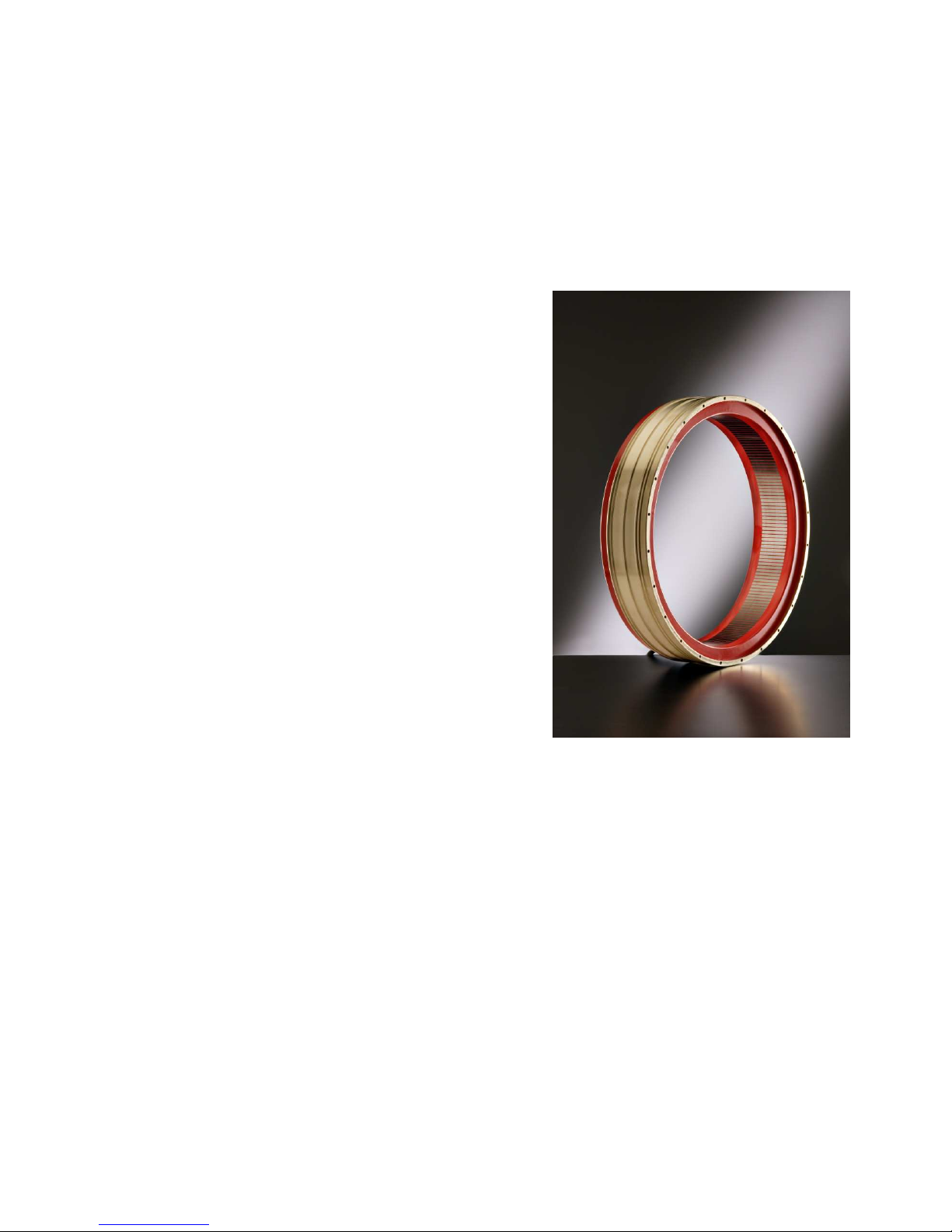
Thin ring, large diameter motors for high torque, low speed
(torque motors)
Typical applications:
• Rotary tables for NC machine tools, often with turning capacity
• Indexers for transfer machines
• NC machine head orientation
• Large rotary tables (glass, packaging, assembly)
•
Carbon fiber deposition machinery
•
Direct drive of mills (concrete, ceramics, rubber
•
Large low speed generators (mini hydro, wind power)
•
Metal forming: electric press and bending
•
Direct drive plastic injection machines
In all these applications, direct drive eliminates play and removes the
need of an accurate mechanical gearbox, which in turn would limit the accuracy and the dynamic
performance of the system. Mechanical brakes-dividers are unnecessary. The table accuracy is the
accuracy of the encoder system. The system is thus extremely simple, flexible and reprogrammable.
The removal of the transmission system and of its backlash and elasticity results in control bandwidth
up to 250 Hz, so that a positioning cycle can be completed with great accuracy within a few msec with
advantage on the machine cycle time.
To ensure adequate servo performance in direct drive high accuracy, high stiffness applications such
as indexing and rotary tables in NC machine tools, the sensor must be sinusoidal so that the drive
Page 9

9 Phase Motion Control
may interpolate the actual position with a resolution at least ten times greater than the required
accuracy. Additionally, the sensor fastening or spring mount must have intrinsic resonance frequency
above 2000 Hz not to limit the overall system performance.
Spindle motors for mills and lathes
long and thin motors, brushless with flux control ability, medium to high speed, high power density, suitable
for heavy machining or control of large inertia loads for spool winding/unwinding. The TK motors have
currently the highest power density and allow the manufacture of electrospindles with torque rating hiterto
unattainable, in the range of several thousand Nm while reaching high speeds in the thousands of rpm.
Spindle type motors are anyway high performance servo motors so another emerging application area is
very short cycle actuation. Recent application are in direct drive of the ram of high speed turret punching
press with stroke rates in excess of 300 strokes/min, or fast, heavy indexing in wire frame welding
machines.
Typical applications:
• Power lathes for automotive,
• Spindle motors for mills and high speed machining centers
•
Wire grid manufacturing
Tube motors, small diameter, for multiple spindle units
Typical applications:
• High speed/power motors where lateral (pitch) space is limited
• Multiple drilling heads
• Swiss type lathes
Page 10

10 Phase Motion Control
Selection guidelines
How to choose the optimal TK motor?
First, define the technical feasibility of the application. In general, all motors share the same physical
limitation, that is, the ability to generate “airgap thrust”, i.e. a sideways thrust between stator and
rotor which is linear thrust in linear motor, and becomes a torque when the motor is round. The
amount of thrust per unit area depends on motor technology but is fundamentally limited by the
properties of the materials (magnets, copper, steel) used in the motors. PM technology offers the
highest specific thrust available today, and this value is gradually increased as the technology
improves. Many factors (cooling conditions, size, air-gap thickness, linear speed etc.) affect this value
which should only be used as a rough guideline. TK rotary motors are characterised by a peak thrust
around 90000 N/m2, continuous thrust with water cooling ~ 55000 N/m2.
The thrust limitation explains why it is always appropriate to use the maximum diameter available to
maximize output torque. In general if a motor
is scaled in diameter, torque is scaled with
the square of diameter, while it scales only
linearly in length. Consequently, to verify
whether a new application is feasible at all, if
the torque availability is expected to be a
limitation, the maximum diameter available
should be determined compatibly with
physical limitation and maximum peripheral
speed (values below 150 m/sec pose no
problem) and the air-gap surface can then be
evaluated. This would give a rough estimate
of motor length and therefore indicate
whether the application is feasible or not.
A typical power and torque curve versus
speed is shown in side figure for a combined
torque/spindle motor with 570 mm diameter,
100 mm axial length; in Fig. 2, the motor
temperature at no load and full loads are
displayed. It can be observed that above the
“knee speed” i.e. the speed of transition
between constant torque and constant power
operation, the motor temperature becomes
progressively independent of motor load.
Page 11

11 Phase Motion Control
Large rings with very limited axial length are the most efficient solution for high torque low speed
applications
, and they have the additional advantage of not needing separate bearings as they can
be generally carried by the same bearings of the load. However, inertia scales with the cube of
diameter, so
where the inertia is the dominant load, long and thin motors are more
appropriate.
A typical example is the direct drive of the ram of high speed punch presses, in which
motion is reversed over 300 times/min, or in high speed flying shears; in this case, tubular, water
cooled TK motors provide the highest performance solution.
Spindle drives
generally demand both high torque and high speed but the diameter is generally
restricted, so they tend to be long and thin. Air-gap hole diameter to length ratios up to 1:3 are
routinely manufactured. In this case, the Phase PM magnet technology allows the manufacture of
extremely
thin stators and rotors which are particularly useful in multispindle applications.
Spindle PM motors
manufactured with the high frequency Phase magnetic technology can operate
both in constant torque and constant power mode. The constant power range, depending on the type,
can exceed 10:1 although this is generally limited by the ability of the drive selected to control a deep
deflux range. When compared to AC Induction spindle motors, the PM motor design offers:
• Rated torque approximately double in
the same size
• Larger shaft compared to the outer
diameter
• Loss only limited to stator, rotor is
“cool” so that bearings can operate
more accurately and reliably
• Solid, “mechanical” rotor (non
laminated) which guarantees
balancing stability
• Wide constant power control range (up
to 10:1) without tap change
• Free from radial flux which may
generate currents in the bearings
In the Phase TK technology, there is no fundamental physical difference between torque motors and
spindle motors; they have the same smoothness and high bandwidth necessary for direct drive
indexing and contouring operation, so that
milling and turning operations on the same motor
are now possible.
There is, however, a fundamental difference between PM and induction spindle drives. In the
induction technology, power is used to magnetize the motor (at low speed, high torque) thus
resulting in limited output torque available; flux reduction is easily obtained by just reducing the
Page 12

12 Phase Motion Control
magnetizing current. Thus the motor is “hot” at max load, and “cool” at no load. PM motors,
conversely, derive the field from high energy permanent magnets, so that no power is required to
build the motor field and more power can be devoted to torque generation. When the flux must be
reduced, however, power must be applied just to lower the field so that PM motors at high speed
need some current even at no load.
Another useful feature of PM technology is the ability to operate with a
wide air-gap, up to several
millimetres in the larger motors. This feature can be useful in machines with important deformations,
such as plastic injection press or impact hammers. As a standard the air-gap is in the order of 1 mm,
radial, and this generally enables designs in which the motor rides on the machine supports without
need of separate bearings.
Page 13

13 Phase Motion Control
Motor morphology and protections
PHASE MOTION CONTROL TK brushless motors are the technical solution with the highest torque
density currently available and are designed for high performance motion control.
Tk motors are frameless and are supplied as separate stator and rotor units for integration into the
final equipment. The motors are all three phases brushless and rotors are based on rare earth, high
energy FeNdB magnets.
TK Motors codification
TK motors consist of two main components one stator (TKST) and one rotor (TKRT). When ordering a
TK motor, the two parts have different codes. The general codification system of TK parts is a s
follows:
Stator TKST.XXX.YYY.ZZZ.K
where:
XXX = Stator outer diameter
YYY = Active part length
ZZZ = Approximate Torque Constant
K = Version
Rotor TKRT.XXX.YYY.K
where:
XXX = Stator outer diameter
YYY = Active part length
K = Version
TKST stator description
A three phase stator, wound and vacuum encapsulated in super high
thermal conductivity compound (for low surface temperature
operation) or impregnated (3 dips, preferred solution for high thermal
cycling), which is either built into a metallic frame carrying the cooling
chambers and coupling O-Rings on the outside and a set of tapped
holes on one side (SQUID type), or into a thin steel microframe,
cylindrical.
The standard SQUID frame is much simpler to use and only requires a
cylindrical cavity, while motor assembly and fastening s just through a
set of screws. The cooling circuit channels are designed by Phase
Motion Control in order to maximize heat exchange and simplify
integration in customer machine.
Page 14

14 Phase Motion Control
Alternatively, the microframe units are ground to h7 tolerance on the
outside diameter and are machined parallel on the two stack sides.
This construction is intended for interference fit or axial pressure
locking. The microframe technology maximizes the usage of space in
the assembly and requires the machine body to carry the cooling
cavities on the inside. It requires some care in the design of the
application.
The insulation system of the motors is rated Class H (magnet wire: Class C) with reinforced insulation
specifically designed for the high DV/dt typical of 600 Vdc servo drive application; the windings are
equipped with thermal sensors and thermal protectors as detailed later in this document.
The star point of the winding is also generally available for filtering purposes.
Page 15

15 Phase Motion Control
TKRT rotor description
A Permanent Magnet Rotor
, with
tubular, isotropic base shape, which
carries the magnets on the outside
periphery, protected by a preloaded
carbon fiber (up to 150 m/sec) ring.
The magnets are generally high
temperature, high energy FeNdB
sintered magnets, Phase Motion
Control manufactured with a special
patented technology. They are
designed for the maximum class
temperature and are virtually impossible to demagnetise except in case of drive failure or improper
operation. If continuous exposure to oil is forecast, special oil resistant magnets can be specified.
The rotor may be fastened on the shaft
either by interference fit or by an array of
axial bolts. The latter construction is
preferred for high torque, low speed
applications such as rotary tables. In
general, the rotor inside profile is
customised to fit with the needs of the
machine provided the required profile is
compatible with the maximum hole required
by the magnetic field, and specified in the
accompanying technical sheets. For proper
operation, the motors need a position
sensor on the shaft (not supplied) both for
field orientation and for position/speed control. The rotor is permanent magnet type and has no
primary losses, so that no rotor cooling is needed in principle. However, the inverter chopper
frequency must be set high enough to ensure that the ripple current, pk-pk is less than 20% of the
nominal rms current to avoid the insurgency of unacceptable, and dangerous, stray rotor loss.
For TK motor until and included size TK1340, we apply phosphating treatment on rotor iron part
and stator steel frame.
This will be done by default and included in the supply unless different requests
Customized frames with integral cooling or even partial machine subassemblies with bearings and
encoders are manufactured on request based on the standard frameless magnetic designs available.
Page 16

16 Phase Motion Control
Type and manufacture of TK motors
TK motors can be supplied in the following types:
Stato
r Standard SQUID
(water cooling jacket)
The stator is inserted into a frame, designed
on customer specification, for liquid cooling
using internal chambers or using the
external surface. The frame carries fixing
holes for interfacing with the driven
machine. O-Ring sealing can be included in
motor supply according to customer
request.
Closed SQUID frame
(Optional)
Same as standard SQUID design, but the
external cooling circuit is closed with a
special water proof carbon fibre sleeve. This
option is available in pre-defined motor
diameters.
Microframe
(Optional)
Inserted on thin steel sleeve machined to h7
tolerance, suitable for hot assembly on the
operating equipment
Rotor
Carbon fibre
(standard)
Tubular ring with magnets, with carbon fibre
sleeve for peripheral rotation speed from 50
to 150m/s. Shaft assembly is performed on
the internal tube diameter generally ground
to H6 tolerance. Shaft interface can be
selected between:
• screw mounting (standard);
• interference mounting w/ or w/o oil
pressure chamber (opt.);
• locking rings seats (opt.);
Standard TK motor rotors are not pre
balanced; final balancing, if necessary, must
take place after rotor assembly on the shaft.
Pre-balancing is available on request
(optional).
Page 17

17 Phase Motion Control
PHASE MOTION CONTROL, together with the Customer, often achieve higher level of efficiency and
performance by designing and supplying semi-custom variants of the TK motors with special winding,
rotor and frame designs.
TK motors express their maximum performance in liquid cooled version. Nevertheless they can be
calculated also for conduction/convection cooling where the performance is defined together with the
customer depending on the available external cooling surface.
For high speed and filed weakening operation liquid cooling is necessary
All the stators windings of TK motors are encapsulated under vacuum with high thermal conductivity
epoxy resin to provide the best mechanical characteristics, protection, insulation and thermal
transfer.
For special application (extra-low weight, very aggressive chemical agents…) the stator can be
provided with impregnation varnish instead of encapsulation
All standard TK motors are supplied with power and sensor wire length 1000mm, different length on
request.
With custom frames also power and signal.connectors can also be supplied.
TK motors are supplied without position sensors
Insulation voltage
All TK PHASE MOTION CONTROL motors are tested with following parameters:
Insulation voltage between Phases-GND 4,5KVDC 60s
Insulation voltage between Phases - Thermal Sensors 3,5KVDC 60s
Insulation voltage between Thermal Sensors - GND 3,5KVDC 60s
Over temperature protection
All TK PHASE MOTION CONTROL motors are supplied with two types of sensors: two PT1000 and
three PTC 130 or PTC 155.
The PTC130 sensors (blue/blue wires) or PTC155 sensors (blue/black
wires) are localized one on each phase, so can react very fast when
the temperature rise of the winding exceeds the tripping threshold in
any one phase. PTC sensors MUST be used for protection. The PTC
sensors are highly non linear, so they are sensed via a threshold
circuit. The sensors guarantee <750 Ohm resistance for Tw <125 C,
and >4000 Ohm resistance for Tw>145 C.
Page 18

18 Phase Motion Control
PT1000 sensors have double insulation to the winding.
All TK stators have two PT1000 sensors. The customer can use either one of them indifferently.
Should a KTY probe fail for any reason, the other one can be used without need for repair.
The PT1000 sensor (white/red wires) is a linear temperature
sensor and provides a reading of actual stator winding
temperature (see figure), which must be used for monitoring
and verification of the motor temperature during the cycle. It
is NOT a protection, because it is localized on only one point
and cannot guarantee true information, when a localized
overcurrent occurs on a zone far from the PT1000.
PT1000sensors are polarized, be sure to respect the +/- wires
assignment at installation.
KTY84-130 sensors (out of production) are available on request in
place of PT100 sensors. The behaviour is similar just with a different
R/T characteristics.
Ground connection
Rotor and stator must be connected to the ground. Do not energize before connecting the grounding
terminals.
0 20 40 60 80 100 120 140 160
400
500
600
700
800
900
1000
1100
1200
1300
1400
1500
Temperature, C
KTY 84 resistance value (Ohm)
Page 19

19 Phase Motion Control
Standard type and size of output power leads
Standard TK motors power leads have Radox 155 insulation for best mechanical and thermal
resistance. Cablex exiting from the stator must be kept as short as possible in order to limit the risk
of damage during handling and transportation.
Typical output cable cross-sections are as follows:
Nominal current
Wire size Cable diameter
In < 15 Arms 1.5 mm2 2.85
15 Arms <= In< 21 Arms 2.5 mm2 3.5
21 Arms <= In< 30 Arms 4 mm2 4.2
30 Arms <= In< 40 Arms 6 mm2 5
40 Arms <= In< 60 Arms 10 mm2 6.4
60 Arms <= In< 90 Arms 16 mm2 7.6
90 Arms<=In<110 Arms 25 mm2 9.2
110 Arms<=In<150 Arms 35 mm2 10.6
150 Arms<=In<200 Arms 50 mm2 12.4
Anti-resonance filter (snubber)
In some conditions of the power supply chain, electrical resonance phenomena may occur in motor
windings. These phenomena can multiply several times the instantaneous voltage of winding versus
ground, leading to excessive stress of the motor insulation system resulting in quick degeneration and
total insulation failure after a short time of operation.
Picture below shows the star point voltage versus ground waveform acquired in a system with
significant resonance. The DC-Bus setting of the power amplifier is only 600 Vdc but the
instantaneous voltage can reach a value as high as 1600 V. The insulation system cannot withstand
this high voltage in long term operation.
Page 20

20
To limit such voltage transients
, P
resonance filter (snubber) which
star terminal (white wire) and m
failure by insulator puncturing.
Ph
NOTE: larger snubbers
in norma
200W) and need to be mounted o
Also PMC suggest , in the first
exceed 90°C.
On request Phase can supply spe
IMPORTANT NOT
configuration. The
PWM modulation m
and/or filter insta
Consequently it is s
type or significant
power amplifier typ
snubber connected
b
tional condition
can dissipate a not negli
installation, to check the temperature of the sn
: the values of snubber filter are calculate
supply cables, type
modification of the power supply components
The peak value must be <= +/-
1200
Phase Motion Control
-
er
(such as different
Page 21

21 Phase Motion Control
Motor integration
During mounting always refer to the assembly drawing in your hand.
Mounting and installation of TK motor are always operation strictly linked to the architecture of the
machine where it must be installed, the following information are only general basic information for
the correct handling of motor.
Stator
The stator installation does not have any particular critical item.
Checklist:
Wiring Protect the wiring from being caught between metallic parts during assembly
and bending in the conduits. Contact PHASE MOTION CONTROL if wiring
appears damaged.
Winding heads generally, if not covered by protection flanges, the winding heads are
vulnerable during the motor integration. avoid all accidental impact with
metallic parts to protect the insulation. Contact PHASE MOTION CONTROL if
damaged.
Liquid cooling When the liquid cooling circuit is assembled and sealed, pay attention to
avoid any loss of liquid from input/output nipples and prevent the cooling
liquid from wetting with the windings. Contact PHASE MOTION CONTROL in
case if loss of liquid on the winding.
Safety distance If there are flanges or metallic parts in proximity of the winding heads, check
that the minimum safety distance between the unprotected winding head
and any grounded metallic part is kept, A value >=6 mm must be ensured to
guarantee correct dielectric rigidity Should a shorter distance be
unavoidable, supplementary insulation may be necessary. In this case
contact PHASE MOTION CONTROL to obtain detailed instructions
Special warnings for liquid cooling systems:
1) With SQUID type frames, or anyway whenever the cooling cavity is made with adjacent rings
and cuts according to Phase Motion technique, carefully check that the inlet and outlet bores
are placed exactly opposite with respect to the nearest cooling ring cut, and are centered on
the first and last ring respectively. Frames with an even number of rings must have inlet and
outlet on the same side; with an odd ring number, input and output are 180
o
opposite.
2) Make sure that under no circumstance the static pressure in the cooling chamber could
exceed 500,000 Pa to prevent motor deformation leading to O-Ring sealing failure (expecially
for motor diameter > 400 mm)
3) Should a mix of water and glycole be used in the cooling circuit, be advised that glycole tends
to dissolve most seals with the except of VITON rubber. All O-rings supplied by Phase are
made of VITON,
Page 22

22 Phase Motion Control
4) It is anyway better to mix the water with an appropriate ion neutralizer (such as ELF Chip
Supra, Total 60L, Eurotherm Eurocold 131, Dowtherm SR-1) instead of Glycole with the
additional benefit of limiting corrosion and clogging risk
5) Do not cool the motor or parts thereof below room temperature to prevent condensation on
the motor, which would quickly degenerate the winding.
6) As far as possible, water must be prevented from leaking on the winding even in case of O-
Ring failure, by means of small drain holes and channels in the appropriate positions.
7) Always make sure that all air bubbles and pockets are removed from the circuit before
performing a full power test and commissioning.
Rotor
The procedure for rotor assembly is determined by the type of coupling with the shaft
Checklist
Insertion of rotor to the shaft All TK rotors have permanent magnets, so avoid mounting
procedure using hot insertion, because there is a risk of rotor
demagnetising if the temperature exceeds 80°C. Contact PHASE
MOTION CONTROL in case of demagnetization
Shaft-Rotor coupling Always respect interference value between shaft and rotor as
indicated by PHASE MOTION CONTROL.
Carbon fiver sleeve On this type of rotors check carefully the integrity of the sleeve.
This preloaded unidirectional composite structure displays
exceptional strength for high speed rotors, but can be damaged by
shocks. Contact PHASE MOTION CONTROL if rotor is damaged.
On request, rotors can be supplied with dual diameter and connection hole for hydraulic disassembly
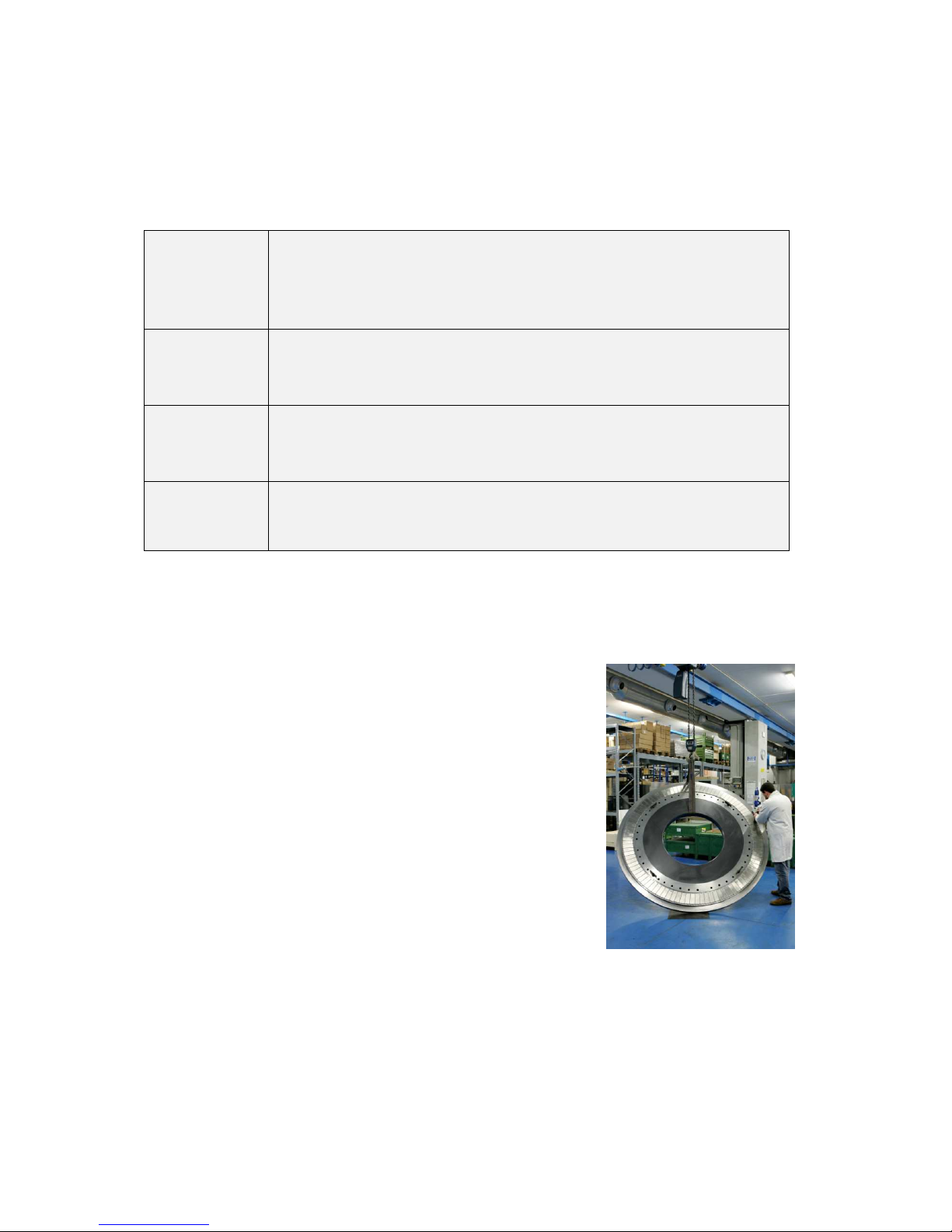
Mounting of the rotor inside the stator
Important warning: Avoid contact or close proximity of the bearings or parts thereof with the rotor
magnets. Magnetized bearings, or magnetized cages, wear rapidly and catastrophycally expecially at
high speed.
If special assembly tools or jigs have not been designed with the application, (i.e. special long shafts
on which the rotor may slide, or positioning pins), then the rotor introduction is performed according
to the following procedure:
1) Make ready a few (at least four) “shims”, (flexible spacers made of non magnetic, not
scratching, material, e.g. brass, copper, lexan or mylar) to interpose between rotor and
stator. The shims should be at least 4 and are placed in the stator hole, equispaced on
the internal circumference of the stator. The shims are best made with thickness
approximately half of the theoretical mechanical air gap. This to guarantee a right
Page 23

23 Phase Motion Control
cantering and to achieve the extraction after rotor mounting. (Remark: on request Phase
can supply mylar shims together with the motor).
2) Immediately prior to rotor instertion in the stator, peel the protective tape from the
surface of the sleeve, check for cleanliness of the rotor surface; if any metallic part is
attracted by the rotor, clean the surface peeling with a adhesive tape.
3) Position the rotor in front of the stator, well centered, making sure that the “shims” are
in the correct positions, and that they can be removed after rotor insertion.
4) Insert the rotor; pay attention to the attraction force of the magnets that tend to “suck”
the rotor inside the stator. This force is about 15 N/mm of rotor diameter and starts to be
felt when the rotor is at some centimetres from the stator stack.
5) If a crane is used to move the rotor check for metallic parts in the rotor trajectory which
could be attracted to the rotor causing damage
6) After rotor insertion the shaft/bearings can be locked, and te shims removed;
7) If the rotor interface is based on bearings on both sides of the rotor, the shims are
extracted when only one bearing is in the correct position. Generally, assembly of the
second bearing is possible and the rotor will be re-centered if the last bearing seat is
machined with a proper conical chamfer.
The photograph shows a mounting example.
Page 24

24 Phase Motion Control
Radial force vs. mounting eccentricity
The magnetic flux in the rotor generates radial
attraction forces. These are perfectly balanced only if
the rotor sits in the center of the stator, and increase
with eccentricity. In practice, this is equivalent to a
“negative stiffness” which must be compensated by a
much higher positive stiffness in the bearing system.
The attraction data can be supplied on demand, the
order of magnitude is shown in the graph in Fig. 3,
for a 1000 Nm, 370 mm diameter, 105 mm long
torque motor with a 1 mm radial airgap.
Check list after integration
1) After rotor installation, if possible, check that the rotation is free and there is no
interference between rotor and stator;
2) Immediately perform a back-EMF testing and compare with the spec; if the back EMF is
within +/- 8% of specified voltage and balance between the 3 phases is better than 5%
the assembly is electricaly and magnetically correct. Note the measured EMF value and
the temperature of the measurement for possible, future diagnostics and rotor
temperature measurement.
3) Repeat the motor insulation test (according to table in paragraph 6.1) to verify the
proper connection and integrity of cables and to be sure that no damage occurred to the
windings during installation. The “Spike Suppressor Unit” (if present) must be
disconnected for this test. It is recommended to execute the test with a DC voltage (AC
insulation test may be disruptive and test results can be affected by errors due to motor
and cables capacitance to ground). Max. leakage current acceptable is 100 uA stable or
reducing in time..
4) Connect the the “Spike Suppressor Unit” between the star point terminal of the motor
and ground.
5) Check the proper sealing of the water cooling circuit (if present) by applying a pressure
of 1.5 bar and verify that the same pressure is maintained;
6) Proceed with the electrical installation.
7) After machine completion proceed with insulation voltage testing according to the
relevant local regulation (CE or UL-CSA).
IMPORTANT NOTE: in case of first installation of a new motor type execute the measure of winding
voltage to ground as reported in previous chapter “Precautions”.
 Loading...