

Page 1
R
TE CH NO LO GY
OWNER’S MANUAL & INSTALL GUIDE
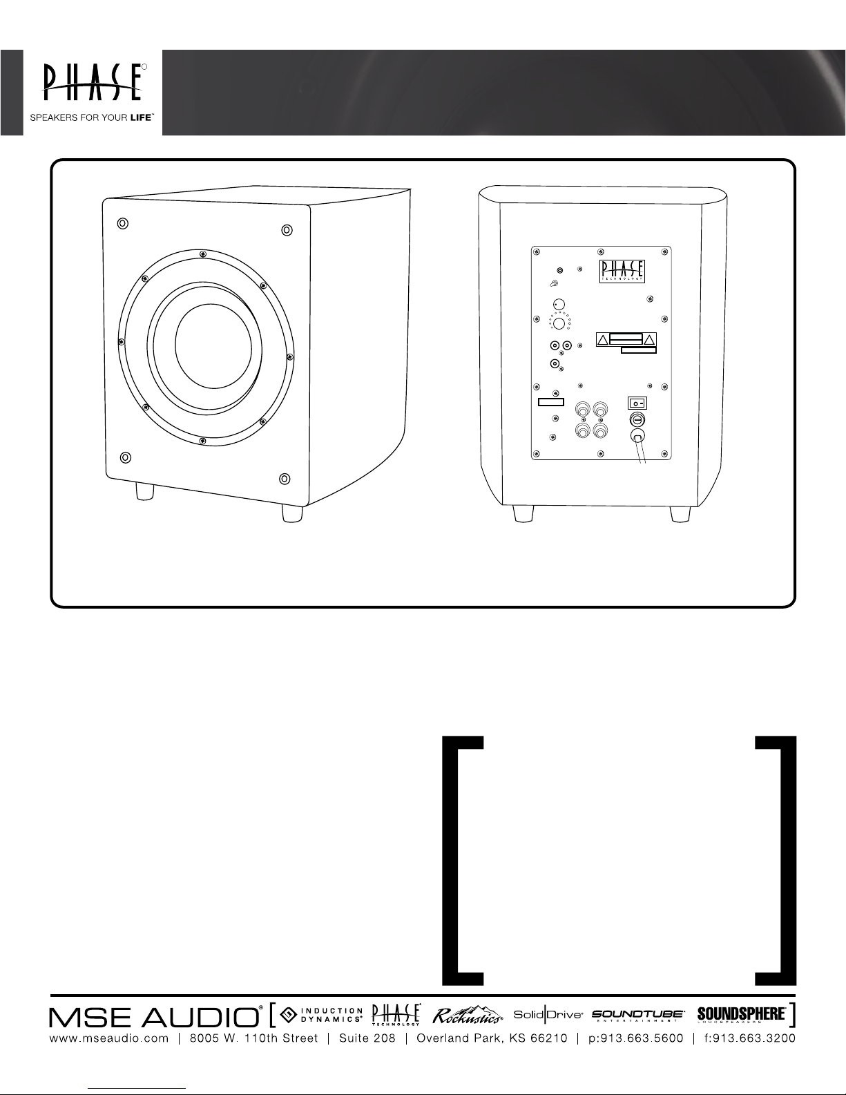
POWER FL-8 • POWER FL-10 • POWER FL-12
STANDBY
/ON
PHASE
0 180
80
Hz
CROSSOVER
FREQUENCY
110Hz40
Hz
BASS LEVEL
LOW LEVEL
INPUT
RL
LFE
IN
HI LEVEL INPUTS
-
BLACK RED
ATTENTION
+
CAUTION
OFF ON
R
L
POWER
120V~ 2A
AC FUSE
205V 2A
[FEATURES] • 250-Watt Amplier • Signal Sensing Auto Turn On/Off • Gain Control • Phase Switch • Variable Crossover
• Line Level/ High Level Inputs • LFE Input • Oversized Surround for Ultra Long Excursion • Servo-Control monitors and
adjusts outpul for dynamic and undistorted response
Thank you for choosing Phase Technology® speakers. We know
there are a wide variety of choices available today, and we sincerely
appreciate your purchase of our product. Phase Technology speakers
are built to exacting standards and will provide many years of listening
enjoyment.
Our speakers are the result of over ve decades of designing
and manufacturing. We hold many key patents in loudspeaker
technology including the soft-dome tweeter. Our mission, our
passion is to constantly advance the art and science of accurate
audio reproduction. Our dedication insures your new speakers will
accurately reproduce all the impact, detail and delicacy of today’s
digital technology.
Regardless of application, serious audiophile listening or home
theater, we recommend that you take the time to read this manual
thoroughly before connecting speakers to your amplier or receiver.
In the highly unlikely event that you should experience a problem with
set-up or operation, please contact one of our authorized dealers for
assistance, or contact us directly.
Phase Technology® Corporation
8005 W. 110th St., Suite 208
Overland Park, KS 66210
855.663.5600 (Domestic)
+1.913.663.5600 (International)
Fax: 913.663.3200
SAFETY INSTRUCTIONS 2
GETTING STARTED AND PRECAUTIONARY NOTES 3
SUBWOOFER PLACEMENT 3
SPEAKER CONNECTIONS 3
SUBWOOFER AMPLIFIER PANEL 4
HOOKING UP YOUR POWER FL SUBWOOFER 4
SUBWOOFER CONNECTIONS 4
AMPLIFIER SETUP AND BASS MANAGEMENT 4
CARING FOR YOUR SPEAKERS 5
MAINTENANCE AND SERVICE 5
TROUBLESHOOTING 5
WARRANTY 6
SPECIFICATIONS 6
Page 2
[SAFETY INSTRUCTIONS]
RISK OF ELECTRIC SHOCK
CAUTION
DO NOT OPEN
8. Ventilation - The appliance should be situated so that its location or position
does not interfere with its proper ventilation. For example, the appliance should not
be situated on a bed, sofa, rug, or similar surface that may block the ventilation
openings; or placed in a built-in installation, such as a bookcase or cabinet that
may impede the ow of air through the ventilation openings.
9. Heat - The appliance should be situated away from heat sources such as
radiators, stoves, or other appliances that produce heat.
CAUTION: To reduce the risk of electric shock, do not remove cover (or back).
No user-serviceable parts inside. Refer servicing to qualied service personnel.
Explanation of Graphical Symbols
The lightning ash with arrowhead symbol, within an
equilateral triangle, is intended to alert you to the presence
of un-insulated “dangerous voltage: within the product’s
enclosure that may be off sufcient magnitude to constitute
a risk of electric shock to persons.
The exclamation point within an equilateral triangle is
intended to alert you to the presence of important operating
and maintenance (servicing) instructions in the literature
accompanying the appliance.
1. Read Instructions - All the safety and operating instructions should be read
before the appliance is operated.
2. Retain Instructions - The safety and operating instructions should be retained
for future reference.
3. Heed Warnings - All warnings on the appliance and in the operating instructions
should be adhered to.
4. Follow Instructions - All operating and other instructions should be followed.
5. Water and Moisture - The appliance should not be used near water - for
example, near a bathtub, washbowl, kitchen sink, laundry tub, in a wet basement,
or near a swimming pool, etc.
6. Carts and Stands - The appliance should be used only with a cart or stand that
is recommended by the manufacturer.
PORTABLE CART WARNING
10. Power Source - The appliance should be connected to a power supply only
of the type described in the operating instructions or as marked on the appliance.
11. Power Cord Protection - Power supply cords should be routed so that they
are not likely to be walked on or pinched by items placed up or against them,
paying particular attention to cords at plugs, convenience receptacles, and the
point where they exit from the appliance.
12. Cleaning - The appliance should be cleaned only as recommended by the
manufacturer.
13. Nonuse Periods - The power cord of the appliance should be unplugged from
the outlet when left unused for a long period of time.
14. Object and Liquid Entry - Care should be taken so that neither objects fall
nor liquids spill into the inside of the appliance.
15. Damage Requiring Service - The application should be serviced by qualied
service personnel when:
a. the power supply cord or the plug has been damaged,
b. objects have fallen onto or liquid has been spilled into the appliance,
c. the appliance has been exposed to rain,
d. the appliance does not appear to operate normally or exhibits a marked change
in performance, or
e. the appliance has been dropped or the cabinet damaged.
16. Servicing - The user should not attempt to service the appliance beyond
those means described in the operating instructions. All other servicing should be
referred to qualied service personnel.
17. Grounding or Polarization - Precautions should be taken so that the
grounding or polarization means of an appliance is not defeated.
APPLICABLE FOR USA, CANADA OR WHERE APPROVED FOR USAGE
7. Wall or Ceiling Mounting - The appliance should be mounted to a wall or
ceiling only as recommended by the manufacturer.
[GETTING STARTED AND PRECAUTIONARY NOTES]
For proper connection and therefore full enjoyment of your new Phase Technology speakers, we encourage you to read this owners’ manual thoroughly, even if you are
very familiar with installing speakers and home entertainment equipment. Speaker placement is very subjective. Placement follows the guidelines for the developers of
multi-channel home entertainment systems, yet is also guided by personal preferences. The proper spacing, location and adjustment of front, rear and center-channel
speakers as well as subwoofers are critical for complete enjoyment of your new speakers. This manual covers these topics thoroughly.
Before connecting your new speakers or other system components, turn the system power off and unplug your amplier to avoid any possibility of damage from power
surges or unbalanced loads before the system is properly connected. Observe speaker polarity carefully! Every cable, speaker terminal and amplier connection are clearly
marked to show their positive (+) and negative (-) polarities. For ideal system performance, always connect the positive side of the cable (marked with a stripe, color and
/or other indicator) to the positive terminals on your speakers and amplier and the negative side of the cable to the negative terminals.
Amplier selection is critical to your enjoyment of your new speakers. If you are considering upgrading your current component amplier or multi-function receiver, we
suggest purchasing as much power as your budget can afford. It will always be preferable to have an affordable high-powered model with fewer “bells and whistles” than
a lower-powered model straining to operate near its power limits. High volume settings that produce audible distortion – indicating an under-powered amplier – could
eventually damage your speakers and your amplier.
Begin and end listening sessions at low volume levels so you will not power up your system the next time with possibly harmful high voltages. A damaging surge also could
result if you change the input source (from FM tuner to CD player, for example) at high volume levels. If you suspect that one channel of your amplier has failed, have it
repaired immediately by your dealer. Damage to your speakers could occur if you switch between the good and defective channels.
CAUTION: TO PREVENT ELECTRIC SHOCK, MATCH WIDE BLADE PLUG TO WIDE SLOT,
INSERT FULLY.
ATTENTION: POUR EVITER LES CHOCS ELECTRIQUES, INTRODUIRE LA LAME LA PLUS
LARGE DE LA FICHE DANS LA BORNE CORRESPONDANTE DE LA PRESE ET POUSSER
JUSQU AU FOND.
2
Page 3

[SUBWOOFER PLACEMENT]
Subwoofer placement is less critical, because the frequencies they reproduce are omni directional. This means the human ear doesn’t perceive these low frequencies as
coming from a specic direction, enabling placement of a subwoofer virtually anywhere in the listening room.
It’s best, however, to keep a subwoofer within the sound eld of the other speakers. The closer the subwoofer is to a wall, the louder and more intense its bass output
will be: this effect is even stronger when the sub is placed in or near a room’s corner. If using two subwoofers, start by placing them next to the front left and right
speakers, in both front corners or one in the corner and one 1/3 of the way along the front wall from the corner. Each room is different. Experiment with these options or
try other locations until you get the best results. If you must choose a less-than-ideal position, the output level of Phase Technology powered subwoofers is adjustable
to compensate for your listening environment.
[SPEAKER CONNECTIONS]
The following instructions apply whether you are using a separate amplier or Home Theater receiver. For simplicity we will use the term “amplier” throughout this manual
to mean both.
SPECIAL NOTE: TURN OFF AND UNPLUG YOUR AMPLIFIER BEFORE CONNECTING SPEAKERS.
SPECIAL NOTE: OBSERVE SPEAKER POLARITY CAREFULLY!
Every cable, speaker and amplifier is clearly marked to show their positive (+) and negative (-) terminals. Amps and speakers may use some combination of
these symbols and/or colors to indicate positive (usually red) and negative (usually black or white) connections. One strand of your cable will also be ridged and/
or marked with a colored line or other indicator on the positive side. For proper polarity and, thus, ideal system performance, always connect the positive side
of the cable to the positive terminals on your speakers and amplifier and the negative side of the cable to the negative terminals.
[SUBWOOFER AMPLIFIER PANEL]
1. Power ON/Auto/OFF: This switch, when left in the “Auto” position, automatically
activates the subwoofer when an audio signal is detected and shuts the subwoofer off
STANDBY
PHASE
0 180
40
Hz
LOW LEVEL
INPUT
RL
/ON
80
Hz
CROSSOVER
FREQUENCY
110
Hz
BASS LEVEL
CAUTION
ATTENTION
LFE
IN
after approximately ten (10) minutes of silence.
2. Phase Control: This adjustment matches the phase - the in and out movement of
speaker cones - to that of your main speakers. Adjust this control by listening to music with
bass content. The setting is correct when the bass sounds the fullest.
3. Crossover Frequency Control: This adjustment varies the point at which the subwoofer
takes over the task of creating low bass frequencies from the rest of the audio signal
permitting additional ne tuning of the total system. A little experimentation with this control
will allow you to match the performance of the subwoofer to the rest of your speakers
resulting in extraordinary, accurate, deep bass response. This control should be turned to
its highest setting when the sub is connected through the Subwoofer out on your receiver.
4. Subwoofer Level Control: Adjusts the volume of bass energy allowing you to customize
overall tonal balance to your individual room acoustics and personal taste.
HI LEVEL INPUTS
-
BLACK RED
R
L
+
POWER
OFFO N
120V~ 2A
[HOOKING UP YOUR POWER FL
SUBWOOFER]
OPTION 1: LOW LEVEL SETUP This is the
recommended method for those ampliers and
receivers that are equipped with a “Subwoofer Out”
or “Pre-Amp Out” connection. Virtually all audio/
video receivers have this connection clearly marked
on the rear panel. Run a dedicated interconnect
cable with RCA connectors from the subwoofer
output jack to the line input on the subwoofer. In
this setup, you will be using the internal crossover
on your processor.
AC FUSE
205V 2A
5. Servo Control: This features automatically protects the subwoofer against damage
which can be caused by excessive amplifer power and/or distortion. Phase Tech’s servo
control system constantly monitors the incoming signal. This active protection circuitry
provides listeners with the full dynamic range of sound while protecting the subwoofer
from potential damage.
6. LFE Input: The Low Frequency Effect (LFE) input bypasses the built-in crossover
network, allowing accurate control of the subwoofer by A/V receivers equipped with their
own “Subwoofer Out” or LFE Output connection.
3
Page 4

[SUBWOOFER CONNECTIONS]
OPTION 2: HIGH LEVEL INPUT SETUP If your amplier or receiver
does not have a dedicated subwoofer output, it will be necessary to
connect your new subwoofer directly to the speaker output terminals
on the back of the unit. In this scenario, you will be running high
quality speaker wires from the left and right front outputs of your
amplier to the high level inputs on the subwoofer. You will then
need a second set of wires to carry the signal from the subwoofer
back to the main speakers.
[AMPLIFIER SETUP AND BASS MANAGEMENT]
Many home theater receivers/processors have a feature that controls how
the bass is processed and delivered to the subwoofer. It also adjusts the
amount of bass that is sent to your satellite speakers. Look carefully in your
amplier or receiver’s instruction manual for details on how to adjust for the
speaker size (sometimes called “Speaker Setup”) for your system.
[CARING FOR YOUR PHASE TECHNOLOGY SPEAKER]
All Phase Technology speakers are nished with a high degree of
craftsmanship in either hand polished paint or vinyl laminates. We
recommend using a lint-free rag with a small amount of glass cleaner to
maintain the long-lasting beauty of the nish. Avoid products containing silicones, oils, oil derivatives, or solvents. Enclosures nished in vinyl laminates may be cleaned
with a damp cloth as necessary.
[MAINTENANCE AND SERVICE]
Because of Phase Technology’s uncompromising quality control programs, it’s unlikely that your speakers will ever need service if connected and used as outlined in this
Owners’ Manual. In the unlikely event that a problem does occur, please contact your Phase Technology dealer. Your dealer has the necessary factory-authorized parts
and trained technicians to quickly restore your speaker to its original performance specications.
[TROUBLESHOOTING]
NO SOUND
1. Verify that all components are plugged in and turned on.
2. Check all speaker wires and cables for loose connections.
3. Check to see if you have selected the proper source on your amplier.
VOICES DO NOT APPEAR TO COME FROM BETWEEN THE SPEAKERS / BASS RESPONSE IS WEAK
1. Verify that all speaker connections from the amplier to the speakers are running PLUS+ to PLUS+ and MINUS- to MINUS-.
2. Check to see if there are any furnishings or plants that may be blocking the output of a speaker.
SOUND, BUT NO BASS (MOST LIKELY IN SYSTEMS WITH A SUBWOOFER)
1. Verify that the subwoofer is plugged into an AC outlet and power is turned on.
2. Check that the speaker wire / cable going from the amplier/receiver to the subwoofer is securely fastened.
3. Check the volume control of the subwoofer.
4. Refer to your amplier/receiver manual to make sure you have adjusted its bass output properly.
MUDDY OR BOOMY BASS
1. Check the volume control for the subwoofer. Excess volume can cause speakers to sound distorted and unnatural.
2. Try adjusting the crossover control on the subwoofer or the subwoofer setup on your receiver to a slightly lower frequency (example:
reduce from 120 Hz to 80 or 60 Hz).
3. If the subwoofer or full size speaker is close to a corner, side or back wall, try moving it away from the wall. This may reduce the
“boomy” bass considerably.
4. Bookshelf speakers placed in a semi-enclosed space or cabinet can articially emphasize bass output. Reduce the bass control on
your amplier or move the speakers to the front of the cabinet. Alternatively, reposition the speakers to a more open location.
DISTORTED SOUND FROM THE SPEAKERS
1. This problem is usually caused by setting the volume control too high. Reduce the amplier/receiver volume to a lower level.
2. If noise and distortion are audible at higher volume levels, your amplier may not be powerful enough. Consider upgrading to a unit
with higher power.
NOTE: Remember, even though your Phase Technology speakers can handle considerable power levels, ANY speaker if used improperly can be damaged. Consult your Phase Technology dealer
for assistance in choosing a new amplier or receiver.
[WARRANTY]
LIMITED WARRANTY: Phase Technology warrants its loudspeakers to be free from defects in material and workmanship for a period of ten (10) years for speaker
product, limited lifetime for CI speakers, and three (3) years for the electronic components to the original purchaser. Purchase must be made from an authorized
Phase Technology dealer.
This warranty does not cover service or parts to repair damage caused by misuse, abuse, damage while in transit, alterations, unauthorized repairs, failure to
follow instructions, re, ood or any other cause beyond the reasonable control of Phase Technology. Defects in speaker cabinets or grilles must be brought to the
attention of your dealer immediately after purchase. This warranty will be void if the products’ serial number has been altered or removed.
Should your Phase Technology product require service, please call the MSE Audio customer service department for a return authorization. All merchandise returned
to Phase Technology without prior authorization will be refused. For your return authorization number, please call 855.663.5600 or email sales@mseaudio.com.
“Speakers for your Life” is a trademark of MSE Audio, Overland Park, Kansas USA. Phase Technology is part of MSE Audio®. www.phasetech.com.
Copyright © 2014 MS Electronics, LLC. All rights reserved. MSE Audio, Phase Technology and PhaseTech are registered trademarks and
4
Page 5

[SPECIFICATIONS]
WOOFER
POWER FL-8
8” Mineral-lled Poly Cone w/ NBR Surround
POWER FL-10 POWER FL-12
10” Mineral-lled Poly Cone w/ NBR Surround
12” Mineral-lled Poly Cone w/ NBR Surround
AMP POWER
FREQ RESPONSE
LOW PASS CROSSOVER
AUTO ON/OFF
SPEAKER LEVEL INPUTS
SPEAKER LEVEL OUTPUTS
LINE LEVEL INPUTS
ENCLOSURE TYPE
DIMENSIONS
WEIGHT
FINISH OPTIONS
250 W Continuous, 600 W Peak
32 Hz - 150 Hz
40 Hz - 110 Hz Variable
YES
2x Binding Post Pairs
N/A
2x Stereo & Mono RCA
Passive Radiator
14.625” H x 11.125” W x 15.25” D
23 lbs.
Black Ash
250 W Continuous, 600 W Peak
26 Hz - 150 Hz
40 Hz - 110 Hz Variable
YES
2x Binding Post Pairs
N/A
2x Stereo & Mono RCA
Passive Radiator
16.25” H x 12.5” W x 18.5” D
30 lbs.
Black Ash
250 W Continuous, 600 W Peak
25 Hz - 150 Hz
40 Hz - 110 Hz Variable
YES
2x Binding Post Pairs
N/A
2x Stereo & Mono RCA
Passive Radiator
18” H x 15” W x 20.75” D
42 lbs.
Black Ash
Page 6

 Loading...