

Install instructions for CS micro series:
T E C H N O L O G Y
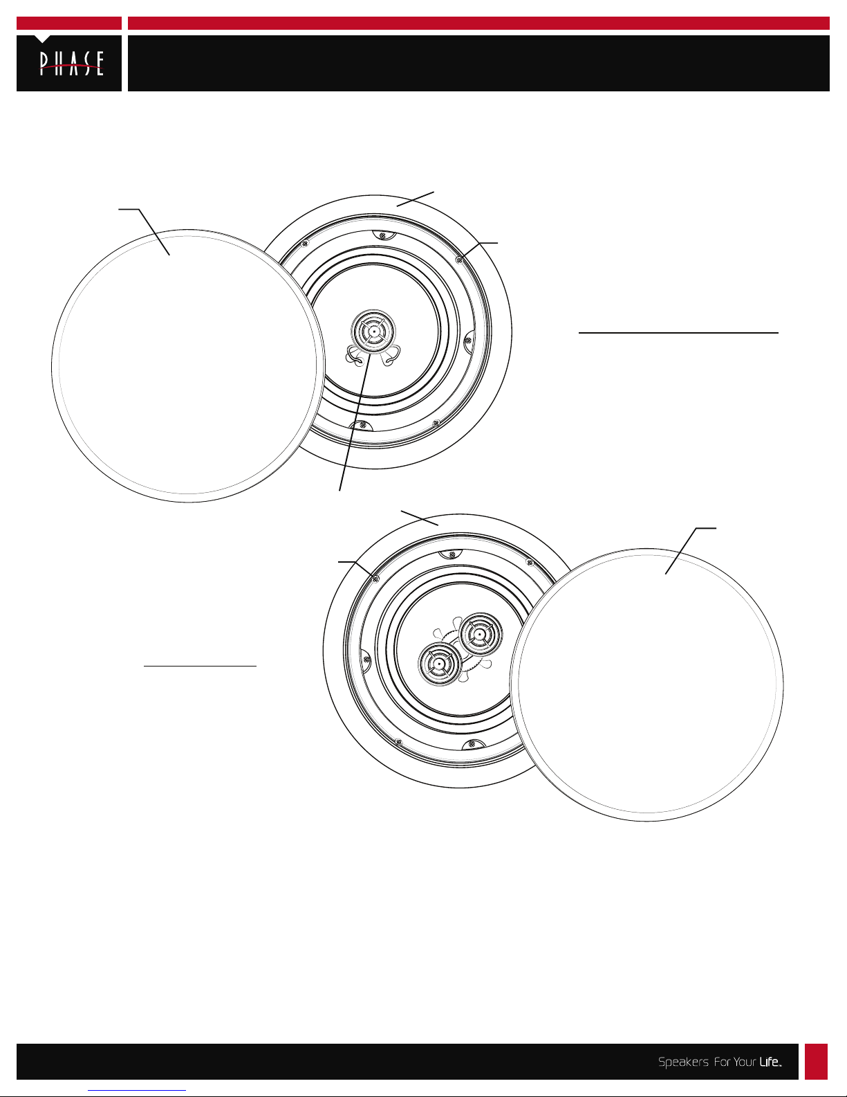
CS-6R/Micro, CS-8R/Micro and CS-6DVT/Micro
Thank you for purchasing Phase Technology Professional Series
speakers. Before installing, please read through this installation
manual thoroughly.
Micro-Flange Grille
Flange
Flange Clamp
Screw (4x)
CS-6R/Micro, CS-8R/Micro
Aimable Tweeter
Flange
Flange Clamp
Screw (4x)
CS-6DVT/Micro
Choose the appropriate mounting location for each speaker.
When deciding upon a location, consider the following:
• Make certain your speaker wires can be run to or are accessible from these
locations.
• Make certain the wall or ceiling material is sturdy enough to support the
weight and vibration of the speakers.
• It is recommended that our pre-construction rough-in bracket assemblies
be used whenever possible in new construction.*
Micro-Flange Grille
• Make certain the area behind the speaker is free of obstacles such as wall
studs, electrical wiring, pipes, etc.
• Each speaker should be positioned properly, relative to the listening area
for good coverage.
• Audio performance and room-to-room isolation will be improved if there is
some berglass insulation placed loosely behind the speaker.
*The RB-14 for the 6” models and AC-CS8R-PCB is for the 8” model rough-in brackets are available for installations in new construction.
8005 W. 110th St., Suite 208 | Overland Park, KS 66210 | (855)663.5600 | www.phasetech.com | www.mseaudio.com
Install instructions for CS micro series, Page 2
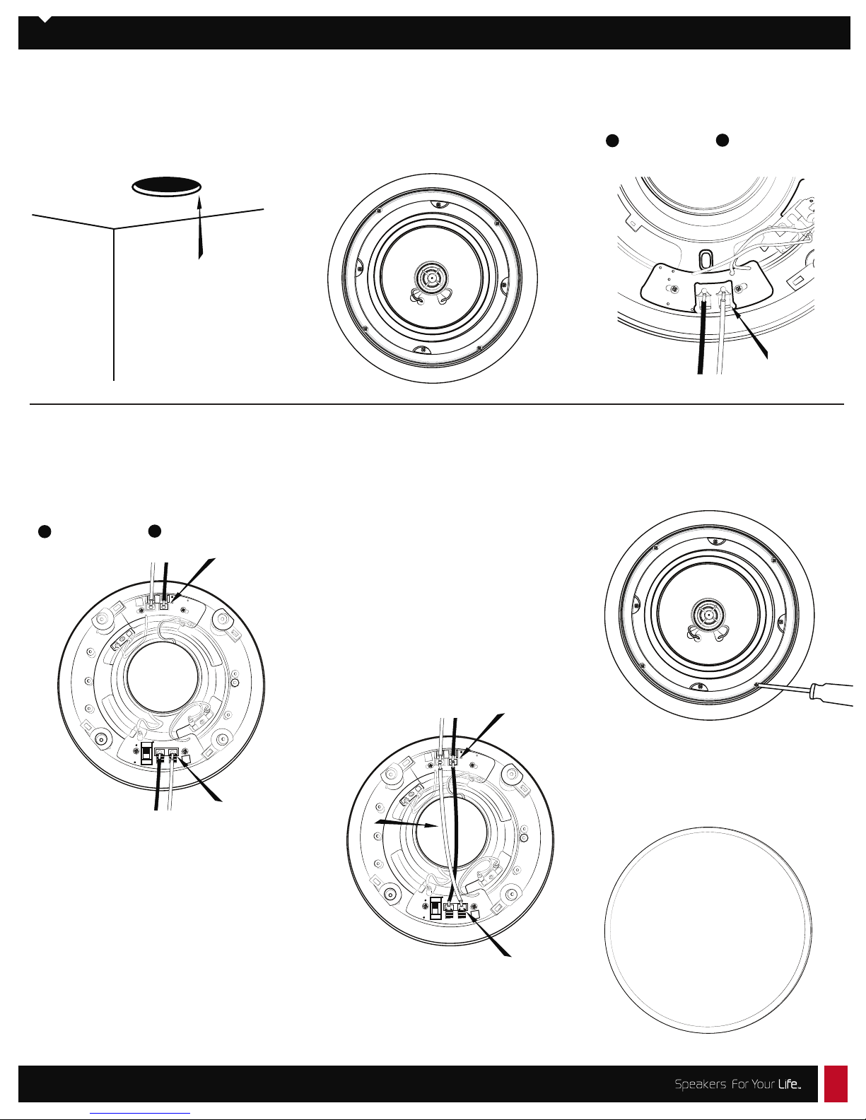
Speaker Installation:
1. Using the supplied cutout template,carefully
mark the area to be cut out. Using a drywall knife or
saw, cut a hole in the drywall and prepare the
speaker wires for connection to the speaker
terminals.
Remove the grille from the speaker assembly.
2.
If it is necessary to paint the speaker grille to
match the ceiling, we recommend that you do
so with several light coats of matching spray paint.
3. Connect the speaker wires to the input
terminals on the rear of the speaker, making
sure no loose strands are exposed.
+
Red/positive Black/negative
_
**Note: for the CS-6DVT/Micro there are several
hookup options. For stereo point-source operation,
connect the speaker wires to the Left and Right
channel input terminals on the rear of the speaker.
Make sure no loose strands are exposed.Please
make sure to check your hookup polarity for proper
operation.
+
Red/positive Black/negative
_
R
100 v
100 v
1u6
1u6
1u6
1u6
Bi
100 v
100 v
L
Di
Stereo point-source conguration
For Surround/Mono: The CS-6DVT/Micro may
also be used as a surround speaker for home
theater applications. For the surround or MONO
mode of operation, connect your speaker wire
to either the left or right channel input as above.
Next connect 2 jumper wires from this same
input terminal to the corresponding input
terminals on the opposite side of the speaker.
Connect the red positive terminal to opposite red
terminal and black negative terminal to opposite
black terminal.
This speaker may be set to either the bi-pole or
di-pole mode of operation using the selector
switch on the rear panel.
Please note that the speaker is a 4 ohm speaker
in this conguration.
R
100 v
100 v
1u6
1u6
4. Carefully position the speaker in the
cutout hole. Using a Phillips screwdriver,
rotate the four clamps to secure the
speaker to the drywall.
CAUTION: Do not over-tighten.
5. Carefully replace the grille by pressing it
into the gap between the ange and the
baffle. Enjoy your new Phase Technology
speakers!
Surround or MONO conguration
8005 W. 110th St., Suite 208 | Overland Park, KS 66210 | (855)663.5600 | www.phasetech.com | www.mseaudio.com
1u6
1u6
Bi
100 v
100 v
L
Di
 Loading...