

Page 1
TE CH NO LO GY
Install instructions for CI rectangular flush mounts models:
CI-SURR
Thank you for purchasing Phase Technology CI Custom
Installation speakers. This eighth generation of high
performance in-wall models features the same superb
sonic performance as our acclaimed PC-Series cabinet
speakers in addition to great flexibility and easy installation, thanks to Phase Tech’s patented QuickMount™
tool-free clamping system. All CI-Series speakers include
self-resetting solid-state PTC protection circuits. This
unique system is able to detect when the speaker is being
over-driven and lowers the speaker volume until the
problem is corrected. The PTC device then resets itself for
normal operation. Other features include liquid-cooled
tweeters for greater power handling, moisture-resistant
materials in all of the critical speaker components, galvanized steel speaker grilles and stainless steel hardware
for improved corrosion resistance, tweeter level controls,
and flexible configurations for Bi-Pole/Di-Pole or one point
stereo operation.
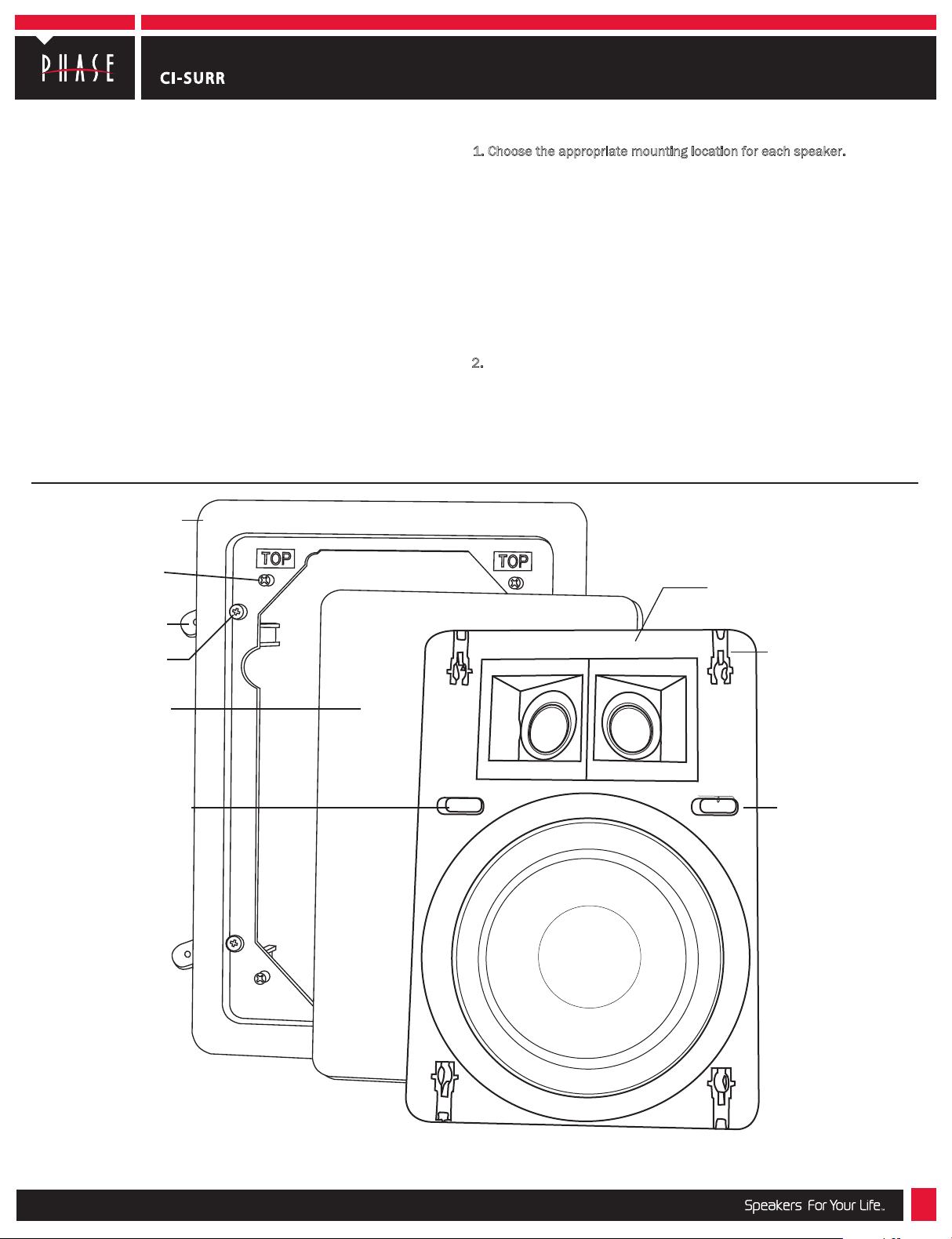
Universal flange
assembly (CI-FG QM)
Quick mount (QM)
clamping post (4x)
Flange Installation:
1. Choose the appropriate mounting location for each speaker.
NOTE – When deciding upon a location consider the following:
•Be certain your speaker wires can be run to or are accessible from these
locations.
•Make certain the wall or ceiling material is sturdy enough to support the
weight and vibration of the speakers.
•It is recommended that our re-construction rough in brackets (part number
RB-18) be used whenever possible in new construction.
•Be certain the area behind the speaker is free of obstacles such as wall
studs, electrical wiring, pipes, etc.
•Each speaker should be positioned properly relative to the listening area for
good coverage.
•Audio performance and room-to-room isolation will be improved if there is
some fiberglass insulation placed loosely behind the speaker.
2. Remove the speaker and flange/grille assemblies from their boxes. Using
the supplied cutout template, carefully mark the area to be cut out. Using a
drywall knife or saw, cut the hole in the drywall and prepare the speaker wires
for connection to the speaker terminals. Use a level to insure that the flange
is square. (Fig. 1a)
Speaker/baffle
assembly
Flange clamp (4x)
Flange clamp
screw (4x)
Grille
Tweeter adjustment
QuickMount
clamp (4x)
Bi-pole/Di-pole switch
™
(QM)
The RB-18 rough-in bracket is available separately for installations in new construction.
6400 Youngerman Circle | Jacksonville, FL 32244 | (888)phase tk | www.phasetech.com
218-1236
Page 2
Install instructions for CI rectangular flush mounts models:
TE CH NO LO GY
Fig. 1a Fig. 1b
CI-SURR
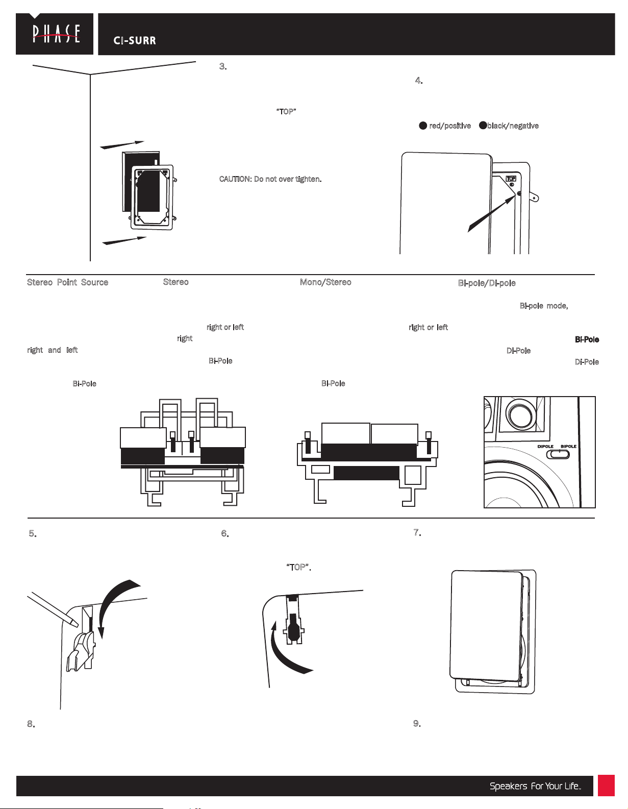
3.
Remove the grille from the mounting flange by
pressing it from behind. Attach the provided white
gasket material to the outside, rear edge of the
flange. Insert the mounting flange into the hole with
the end marked
clamping screws one turn (counter clockwise) to
release the clamp. Next tighten all 4 flange clamp
screws evenly to secure the flange to the wall. It is
best to tighten each screw with the same amount of
force (torque). (Fig. 1b)
CAUTION: Do not over tighten.
“TOP”
facing up. Loosen the flange
Speaker Installation:
4.
Select the desired configuration for your
CI-Surround speaker as listed below. Connect speaker
wires to spring-loaded input terminals on rear of
speaker, making sure no loose strands are exposed.
+
red/positive black/negative
flange screw
-
Stereo Point Source – 8 ohms -
Use this configuration to combine left
and right channels for full fidelity
sound from a single loudspeaker
stereo source. (Fig. 2a) Set jumper
plugs in the stereo position. Connect
right and left signal wires to the
spring-loaded terminals on the rear of
the speaker. Leave the front panel
switch in the Bi-Pole position.
Stereo – 8 ohms – Use this configu-
ration to drive one channel (left or
right) of a stereo pair. Set jumper
plugs in the stereo position. (Fig. 2a)
Connect the right or left signal wire to
the right set of terminals on the rear
of the speaker. Leave the front panel
switch in the Bi-Pole position.
MONO
Fig. 2a Fig. 2b Fig. 2c
5. Use the provided tool to fully open the Quick
Mount Clamps (QM). If the tool is not available,
a small screw driver can be used.
(Fig. 3a)
STEREO
Mono/Stereo – 4 ohms – Use this
configuration to drive one channel (left or
right) of a stereo pair with a 4 ohm speaker
load. Set jumper plugs in the mono
position. (Fig. 2b) Connect the right or left
signal wire to the left set of posts on the
rear of the speaker. Acoustic output of the
speaker is increased by 3 dB in this
configuration. Leave the front panel switch
in the Bi-Pole position
MONO
STEREO
6. Insert the baffle into the mounting flange,
aligning QM clamps with the four QM posts. Also
make sure that the tweeter is placed at the end of
the flange marked “TOP”.
Bi-pole/Di-pole – 4 ohms – Use this
configuration for home theater surround
applications. For Bi-pole mode, connect
as in the Mono/Stereo instructions: one
speaker to each surround channel and
set the front panel switch to the Bi-Pole
position. For Di-Pole mode simply move
the front panel switch to the Di-Pole
position. (Fig. 2c)
7. Tighten down the four QM clamps by pressing them
down flush with the baffle’s surface. (Fig. 3b)
8.
Using some familiar source material, listen
to the tweeter’s balance with the level control
in each of its three positions to find your
favorite.
6400 Youngerman Circle | Jacksonville, FL 32244 | (888)phase tk | www.phasetech.com
Fig. 3bFig. 3a
9.
Carefully install grille by pressing it into the gap
between the flange and the baffle and enjoy your
new Phase Technology CI speakers. (
Fig. 4
Fig. 4)
 Loading...