

Page 1

0
AxN
CONFIGURABLE MOTION
CONTROL PLATFORM
Installation Manual
Support Model:
AxN Size5: AxN 90.150.4, AxN 110.200.4
Version:V1.0(E)
Page 2

Page 3

1
Summary
1 Mechanical Installation .............................................................................................................. 3
1.1 Notes for Operation ...................................................................................................... 3
1.2 Installation Environment ............................................................................................... 4
1.3 Overall Dimensions ....................................................................................................... 5
1.4 Installation Orientation ................................................................................................. 6
1.5 Installation Spacing ....................................................................................................... 7
2 Main Circuit Wiring .................................................................................................................... 8
2.1 AC Power Supply Input .................................................................................................. 8
2.1.1 AC Power Supply Requirement .......................................................................... 8
2.1.2 AC Power Supply Cable Fabrication ................................................................... 8
2.1.3 AC Power Supply Input Installation .................................................................. 11
2.2 DC Power Supply Input ................................................................................................ 14
2.2.1 DC Power Supply Requirement ........................................................................ 14
2.2.2 DC Power Supply Cable Fabrication ................................................................. 14
2.2.3 DC Power Supply Input Installation .................................................................. 17
2.3 Brake Resistor .............................................................................................................. 20
2.3.1 Internal Brake Resistor ..................................................................................... 20
2.3.2 Internal Brake Resistor Installation .................................................................. 20
2.3.3 External Brake Resistor .................................................................................... 21
2.3.4 External Brake Resistor Installation .................................................................. 22
2.4 Motor Power Output ................................................................................................... 25
2.4.1 Motor Power Output Cable Fabrication ........................................................... 25
2.4.2 Motor Power Output Installation ..................................................................... 28
3 Control Circuit Wiring .............................................................................................................. 31
3.1 Auxiliary Power Supply (AUX_Power) ......................................................................... 31
3.1.1 Auxiliary Power Supply Requirement ............................................................... 31
3.1.2 Auxiliary Power Supply Cable Fabrication ........................................................ 31
3.1.3 Auxiliary Power Supply Installation .................................................................. 32
3.2 System Relay (R1) ........................................................................................................ 34
4 Communication Port ................................................................................................................ 36
4.1 Overview of Communication Port Panel ..................................................................... 36
4.2 E1 —— Main Encoder Port ......................................................................................... 37
4.2.1 Sincos Encoder ................................................................................................. 38
4.2.2 Endat Encoder ................................................................................................. 39
4.2.3 Digital Incremental Encoder with Hall .............................................................. 40
4.2.4 Resolver ........................................................................................................... 41
4.2.5 Hiperface Encoder ........................................................................................... 42
4.3 S1 —— Serial Bus Port ................................................................................................ 43
4.3.1 RS-232 ............................................................................................................. 43
4.3.2 RS422/485 ....................................................................................................... 46
4.3.3 Auxiliary CAN ................................................................................................... 47
4.4 C1 —— Main CAN Port ............................................................................................... 49
Page 4

2
4.4.1 Main CAN ......................................................................................................... 49
4.4.2 Auxiliary Encoder ............................................................................................. 51
4.5 EtherCAT IN/OUT——EtherCAT Port ........................................................................... 52
4.6 U1/U2 —— User Connectors ...................................................................................... 53
4.7 U3/U4 —— Insulated User Connectors ...................................................................... 55
Page 5

3
1 Mechanical Installation
1.1 Notes for Operation
Avoid
Please be sure to avoid:
1. penetration of damp into the device;
2. aggressive or conductive substances in the immediate vicinity;
3. explosive and flammable substances in the immediate vicinity;
4. drill chippings, screws or foreign bodies dropping into the device;
5. ventilation openings being covered over, as otherwise the device may be damaged
Note
Note the following points:
1. Make sure every part of the drive is anchored before moving the drive. Failure to comply may
result in minor or moderate injury from the drive parts falling.
2. Observe proper electrostatic discharge (ESD) procedures when handling the drive. Failure to
comply could result in ESD damage to the drive circuitry;
3. Prevent foreign matter such as metal shavings or wire clippings from falling into the drive
during installation and project construction. Failure to comply could result in damage to the
drive. Place a temporary cover over the top of the drive during installation. Remove the
temporary cover before start-up, as the cover will reduce ventilation and cause the drive to
overheat.
Install proper cooling to ensure the temperature in the enclosure does not exceed 40 °C.
Page 6

4
1.2 Installation Environment
To help prolong the optimum performance life of the drive, install the drive in the proper
environment. The table below provides description of the appropriate environment for the drive.
Environment
Condition
Installation Area
Indoor
Ambient
Temperature
0℃ to 40℃, up to 50℃ with power reduction (2%/℃)
Drive reliability improves in environments without wide temperature
fluctuations.
When using an enclosure panel, install a cooling fan or air conditioner in the
area to ensure that the air temperature inside the enclosure does not exceed
the specified levels.
Do not allow ice to develop on the drive.
Humidity
5 to 90% without condensation
Surrounding Area
Install the drive in an area free from:
1. oil mist and dust
2. metal shavings, oil, water or other foreign materials
3. radioactive materials
4. combustible materials (e.g., wood)
5. harmful gases and liquids
6. excessive vibration
7. chlorides
Altitude
Up to 1000m above MSL, over 1000 m above MSL with power reduction ( 3%
per 100m)
Vibration
Amplitude up to 0.3mm at 2 to 9 Hz
Acceleration up to 1m/s2 at 9 to 200 Hz
Orientation
Install the drive vertically to maintain maximum cooling effects.
Page 7
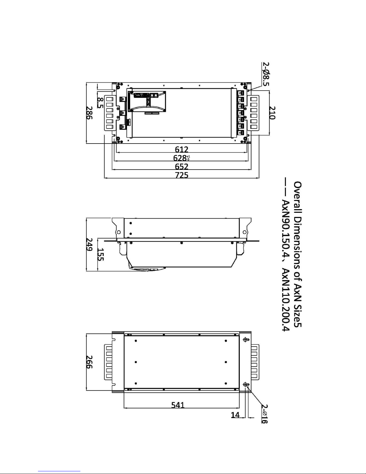
5
1.3 Overall Dimensions
Page 8
6
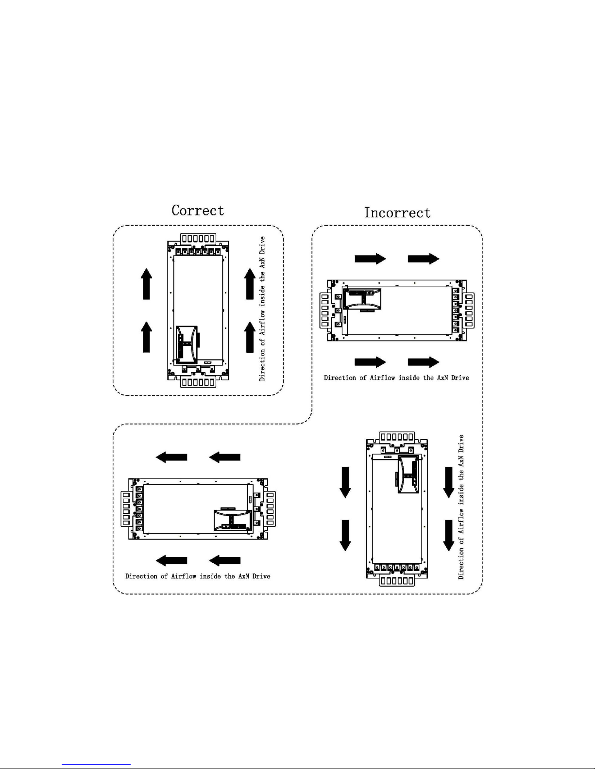
1.4 Installation Orientation
To maintain proper cooling, install the AxN drive upright inside the switch cabinet as illustrated
below:
WARNING: The airflow inside the drive must be upright after installation as illustrated below. If
other form of installation must be taken, CONNECT PMC ENGINEER BEFORE INSTALLATION.
Installation Orientation of AxN Size5
Page 9
7
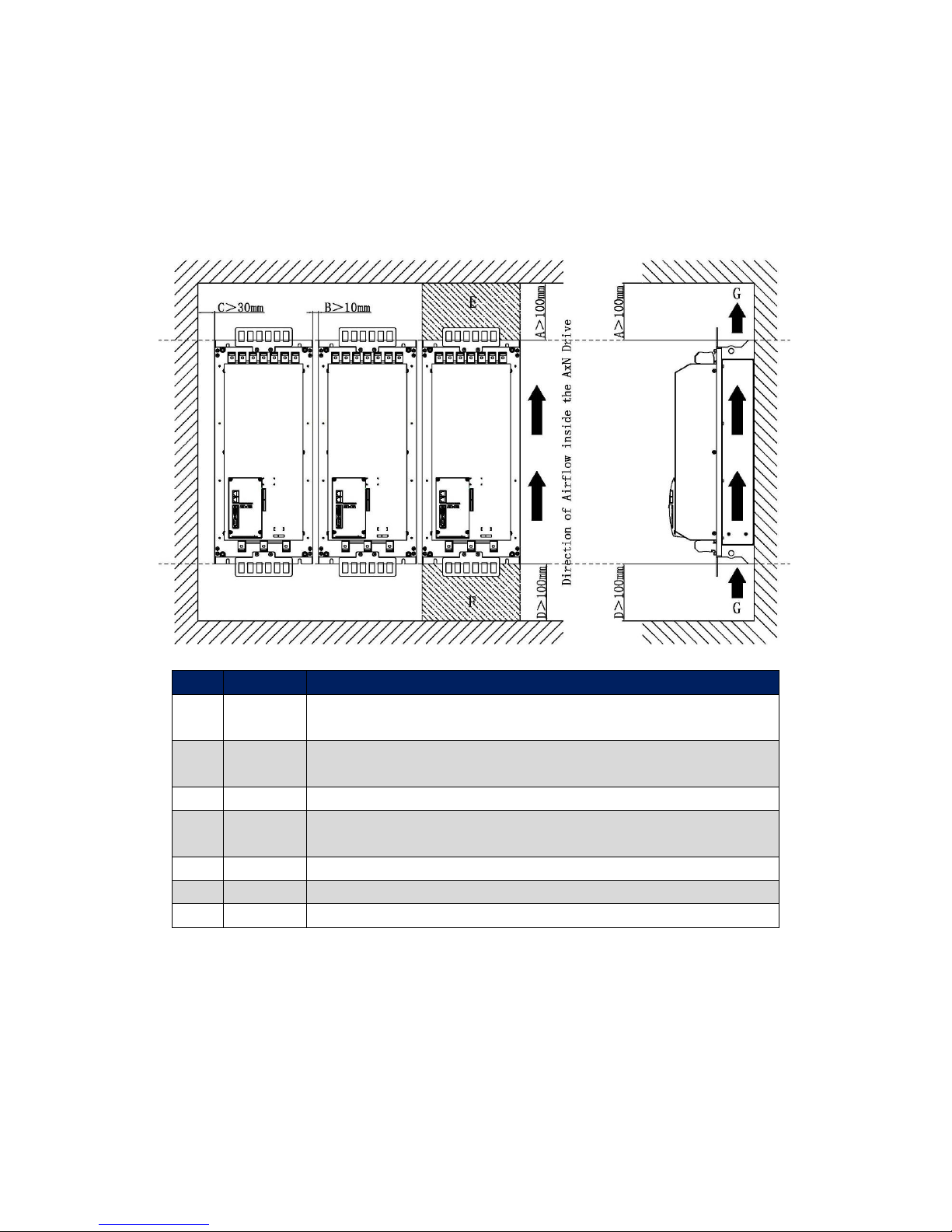
1.5 Installation Spacing
To maintain sufficient space for airflow and wiring, the space between AxN drive and other device
(including other AxN drives) must comply the requirement below.
Correct Installation Spacing of AxN Series Drive
No.
Distance
Description
A
>100mm
The distance between the top of the switch cabinet, to ensure enough
space for air-out.
B
>10mm
The distance between other device (including other AxN drives and
peripheral devices)
C
>30mm
The distance between the inside wall of the switch cabinet.
D
>100mm
The distance between the bottom of the switch cabinet, to ensure enough
space for air-in.
E
>100mm
Air-out area, do not place any other device in this area
F
>100mm
Air-in area, do not place any other device in this area
G Airflow Direction
NOTE: The switch cabinet must have air outlets and inlets to ensure the thermal exchange between
the cold air outside and the hot air inside.
Page 10
8
2 Main Circuit Wiring
2.1 AC Power Supply Input
2.1.1 AC Power Supply Requirement
Mains Supply
AxN Series
Voltage
150 ~ 500Vac
Type
Three-phase AC power
Frequency
50/60Hz
Fluctuation of Frequency
±10% (45 ~ 66Hz)
Asymmetry
±3%
2.1.2 AC Power Supply Cable Fabrication
AC power supply cable is the cable which connect the AxN Size5 Drive with the filter. The
connection between AC power supply and the filter is not mentioned in this manual, and should
be connected properly based on the real application.
Step 1: Cable Selection
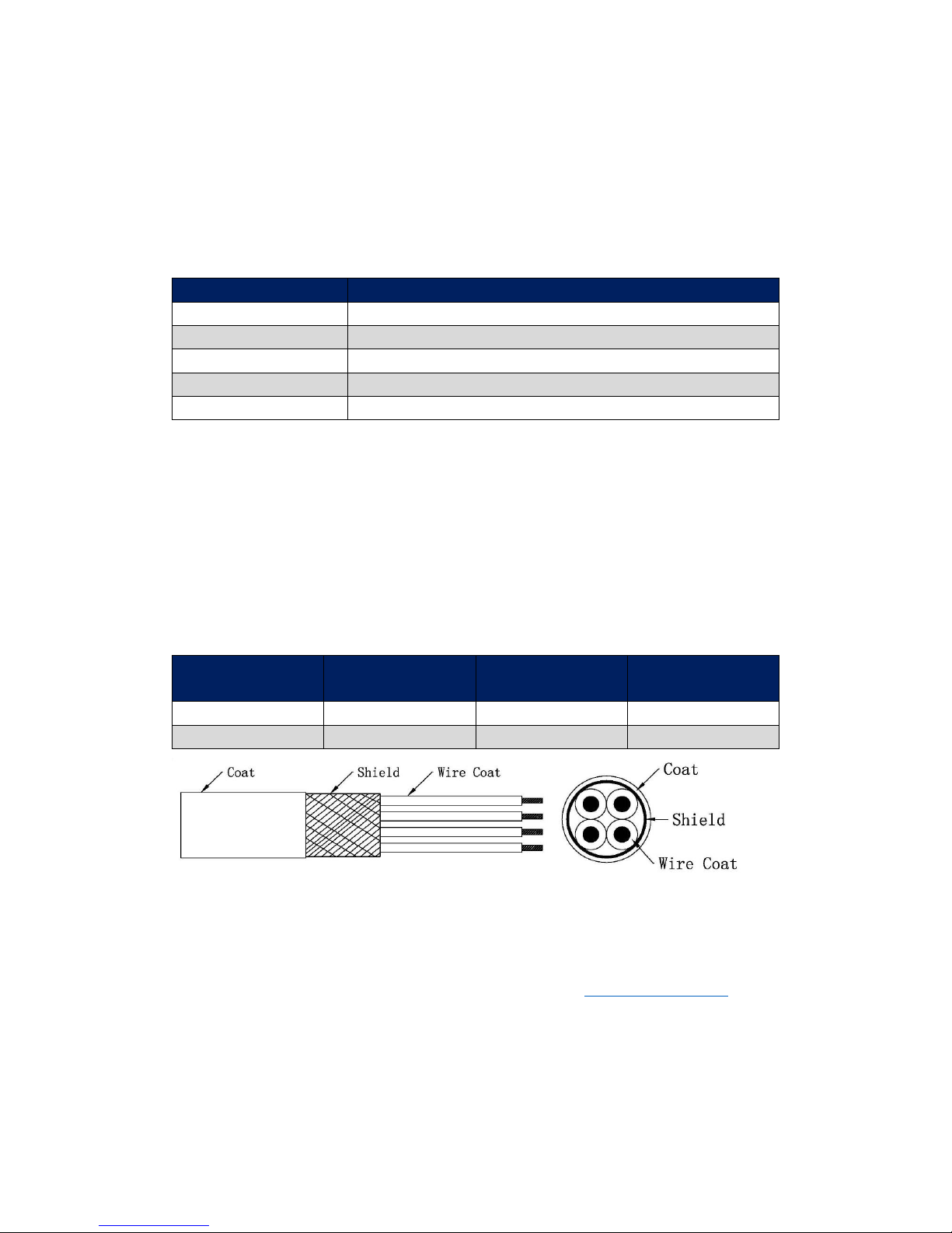
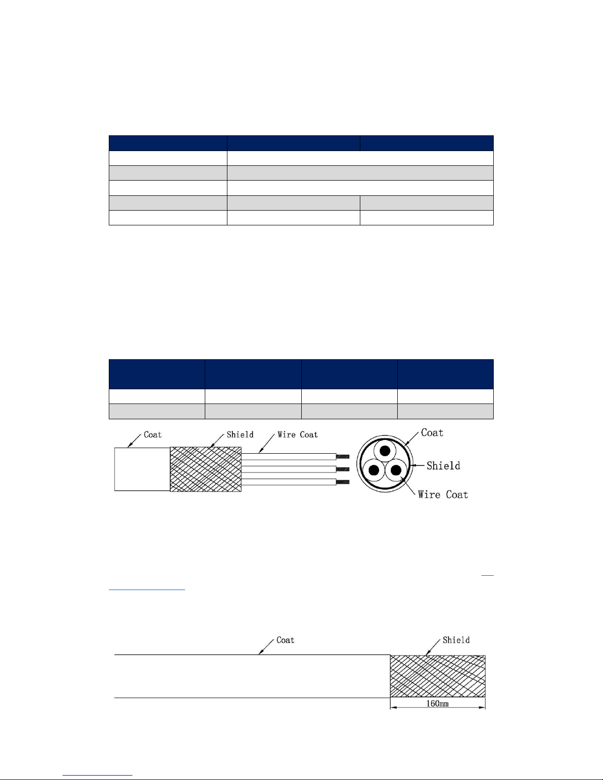
AxN Size5 drive must use a 4 wire cable with shield as its AC power supply cable. Refer to the
table below to select the appropriate cable:
AxN Size5
Current (A rms)
Recommended
Gauge (mm2)
Recommended
Gauge (AWG)
AxN 90.150.4
90
21.15
4
AxN 110.200.4
110
26.67
3
Step 2: Cable Length Measurement
The AC power supply cable is used to connect the output of the filter with the Power Input Port
(P1) of AxN Size5 Drive. To minimize the interference, the filter must be installed in close proximity
to AxN Size5 Drive as much as possible. But, the distance between two devices should also comply
with the Installation Space Regulation of AxN Size5 Drive (Refer to 1.5 Installation Spacing).
NOTE: The length of AC power supply cable should NOT exceed 0.5m.
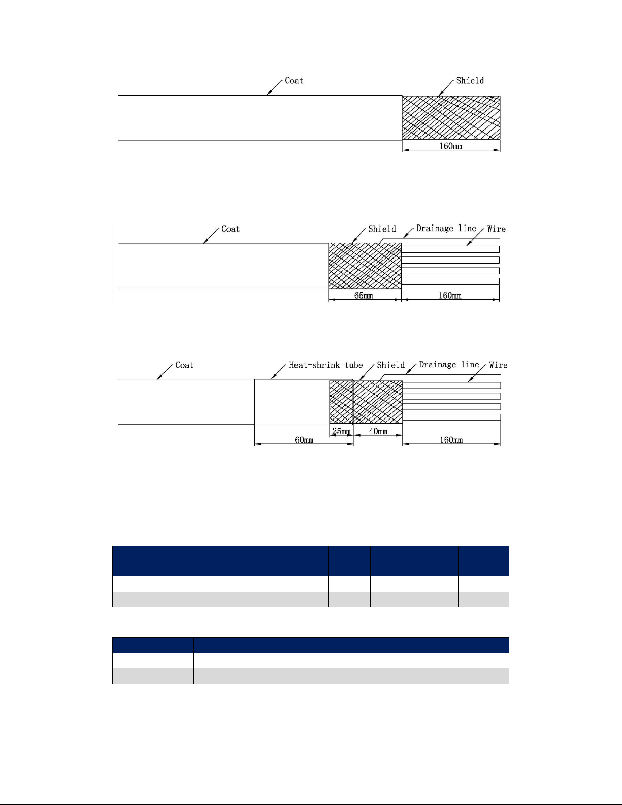
Step 3: Strip the Cable Coat
Strip the outside coat of the AC power supply cable for 160mm and reveal the inside shield.
Page 11
9
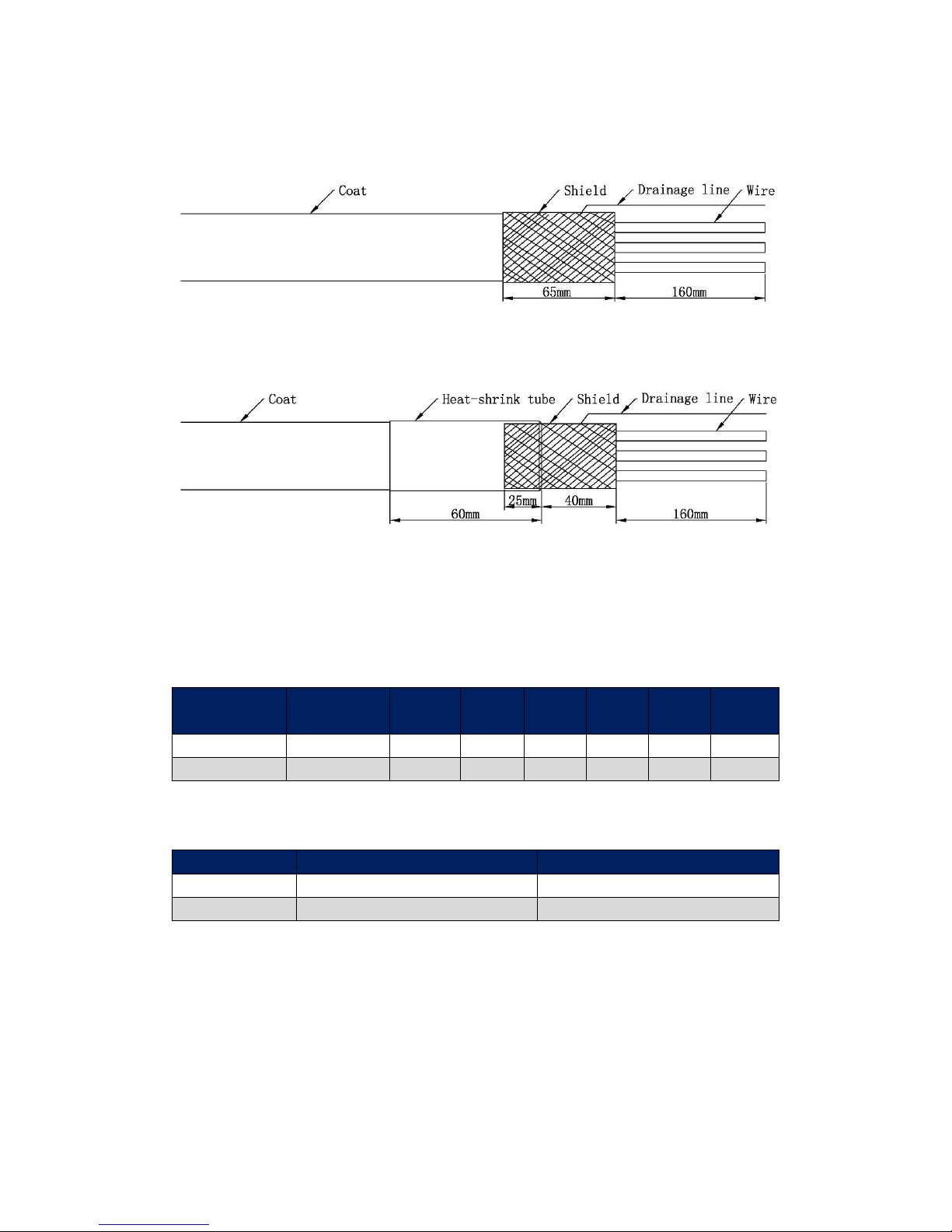
Step 4: Make the Grounding Shield
Leave 65mm Shield as the grounding shield and turn it to the outside of the coat. Then, weld a wire
on the shield as the drainage line.
Step 5: Fix the Grounding Shield
Use a 60mm heat-shrink tube to fix the grounding shield and leave 40mm shield outside.
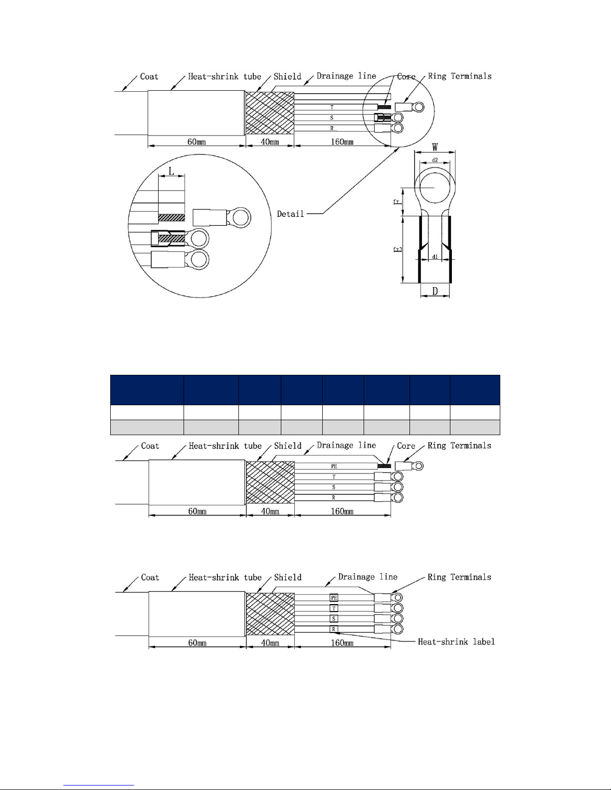
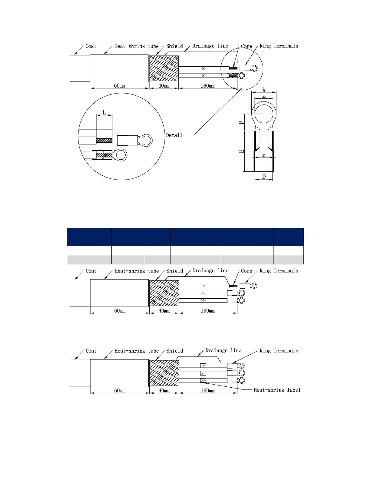
Step 6: Make the Phase Wires
Choose 3 wires of the cable as the phase wires (R, S and T). Crimping pre-insulated Terminals on
the wires will enhance the connection stability and simplicity between the cable and drive. AxN
Size5 series drives are recommended to use the RNY Series Ring Terminals manufactured by KST.
Refer to the following table to select the appropriate terminal:
AxN Size5
Ring
Terminals
d2(mm)
W(mm)
F(mm)
E(mm)
D(mm)
d1(mm)
AxN 90.150.4
RNYB22-8
8.4
16.5
13.5
24
13
7.7
AxN 110.200.4
RNYB22-8
8.4
16.5
13.5
24
13
7.7
Strip the wires for L mm (1 ≤ L ≤ E), the recommend strip length is E/2 mm, refer to the following
table to select an appropriate length:
AxN Size5
Strip Length (mm)
Recommended Strip Length (mm)
AxN 90.150.4
1 ~ 24
12
AxN 110.200.4
1 ~ 24
12
Page 12
10
Step 7: Connect the PE wire with Shield
Use the same method to make the remaining wire as the PE wire. Then crimp the PE wire into the
Ring Terminal along with the drainage line. Refer to the following table to select the appropriate
terminal:
AxN Size5
Ring
Terminals
d2(mm)
W(mm)
F(mm)
E(mm)
D(mm)
d1(mm)
AxN 90.150.4
RNYBS22-6
6.4
12.2
15.1
24
13
7.7
AxN 110.200.4
RNYBS22-6
6.4
12.2
15.1
24
13
7.7
Step 8: Check and Mark
Check every wire and the connection between shield and PE wire, then label each wire.
Page 13
11
2.1.3 AC Power Supply Input Installation
Step 1: Check the Power Supply Type and Voltage
Make sure that the mains power supply is a 3 phase AC power supply, and its voltage is 150 ~ 500
Vac.
Step 2: Install the Filter
Connect the filter to the AC power supply. Then, connect one end of the AC power supply cable to
the filter. Fuses or Breaker can be installed before the filter based on the real application.
NOTE: To minimize the interference, the filter must be installed in close proximity to AxN Size5
Drive as much as possible. But, the distance between two devices should also comply with the
Installation Space Regulation of AxN Size5 Drive (Refer to 1.5 Installation Spacing). The length of
AC power supply cable should NOT exceed 0.5m.
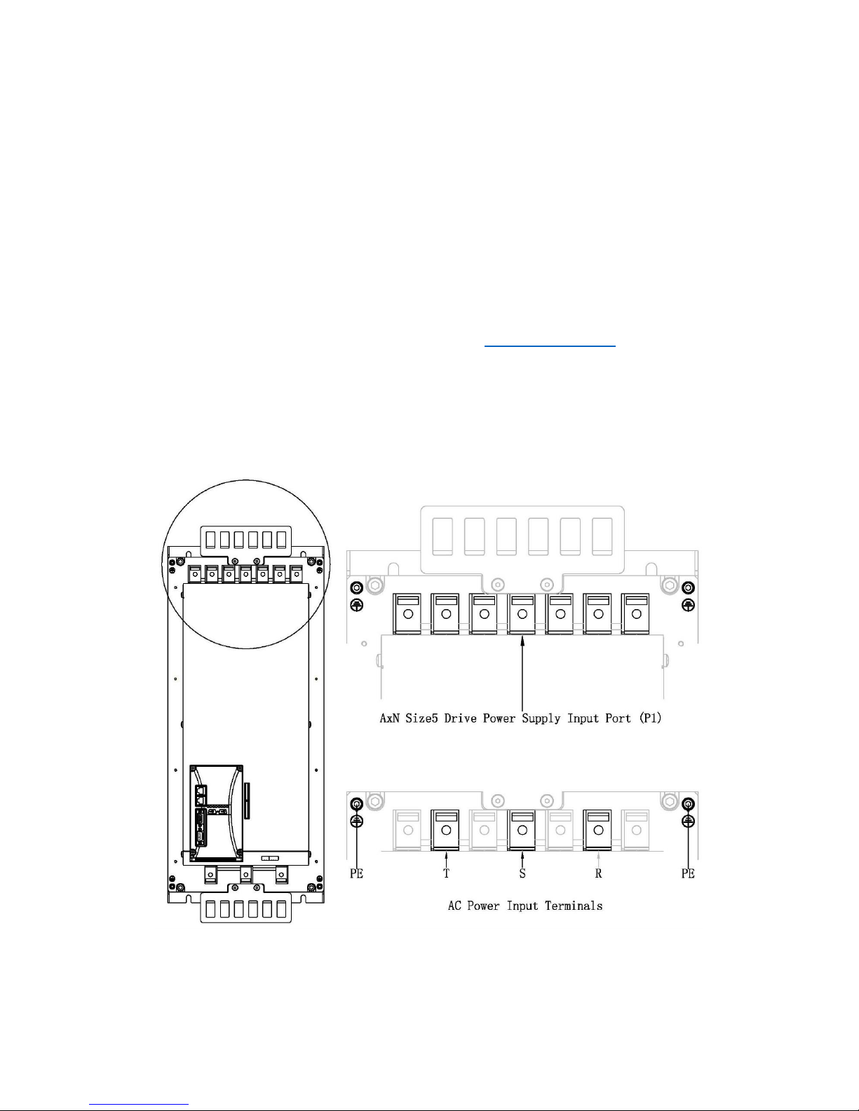
Step 3: Find out the AC Power Input Terminals
PE, T, S and R, these are the four terminals called AC Power Input Terminals. AxN Size5 Drive’s AC
Power Input Terminals are in the Power Supply Input Port (P1) which is on the top of the drive.
Refer to the following figures for exact locations and terminal Assignment.
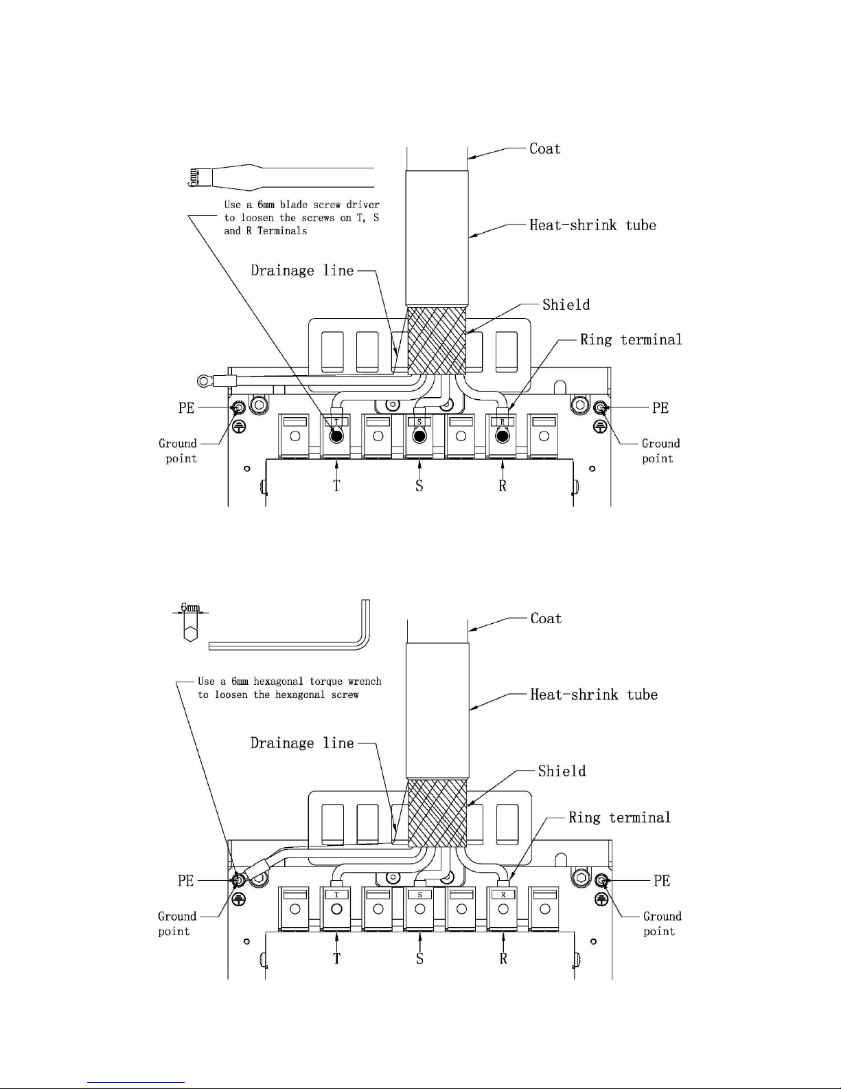
Step 4: Install Phase Wires (T, S and R)
Use a 6mm blade screw driver to loosen the screws on T, S and R Terminals which are in the drive’s
Power Supply Input Port (P1). Insert the AC power supply cable’s phase wires into the
Page 14
12
corresponding terminals: T to T, S to S and R to R. Then use a 6mm blade screw driver to tight the
screws.
Step 5: Install Grounding Wire
Use a 6mm hexagonal torque wrench to loosen the hexagonal screw on either PE Terminal which
is on the drive’s body. Fix the grounding wire on the PE terminal.
Page 15

13
Step 6: Cable Fixing
Use a hose clamp to fix the cable on the cable support. Make sure that the cable shield has a large-
area contact against the cable support, so that they can together be grounded through drive
housing.
Page 16
14
2.2 DC Power Supply Input
2.2.1 DC Power Supply Requirement
Main Supply
AxN 90.150.4
AxN 110.200.4
Voltage
565V
Type
DC power
Fluctuation of Voltage
0 ~ 800V
Nominal Power
62.4KW
76.2 KW
Peak Power
103.9KW
138.6 KW
2.2.2 DC Power Supply Cable Fabrication
DC power supply cable is the cable which connect the AxN Size5 Drive with the DC power supply.
This manual only mention the cable fabrication of AxN drive side. The power supply side should be
fabricated based on the requirement of the DC power supply
Step 1: Cable Selection
AxN Size5 drive must use a 3 wire cable with shield as its DC power supply cable. Refer to the
table below to select the appropriate cable:
AxN Size5
Current (A rms)
Recommended
Gauge (mm2)
Recommended
Gauge (AWG)
AxN 90.150.4
110.4
26.67
3
AxN 110.200.4
134.9
33.62
2
Step 2: Cable Length Measurement
The AC power supply cable is used to connect the output of the DC power supply with the Power
Input Port (P1) of AxN Size5 Drive. To minimize the interference, the DC power supply must be
installed in close proximity to AxN Size5 Drive as much as possible. But, the distance between two
devices should also comply with the Installation Space Regulation of AxN Size5 Drive (Refer to 1.5
Installation Spacing).
Step 3: Strip the Cable Coat
Strip the outside coat of the DC power supply cable for 160mm and reveal the inside shield.
Page 17
15
Step 4: Make the Grounding Shield
Leave 65mm Shield as the grounding shield and turn it to the outside of the coat. Then, weld a wire
on the shield as the drainage line.
Step 5: Fix the Grounding Shield
Use a 60mm heat-shrink tube to fix the grounding shield and leave 40mm shield outside.
Step 6: Make the Phase Wires
Choose 2 wires of the cable as DC+ and DC-. Crimping pre-insulated Terminals on the wires will
enhance the connection stability and simplicity between the cable and drive. AxN Size5 series
drives are recommended to use the RNY series Ring Terminals manufactured by KST. Refer to the
following table to select the appropriate terminal:
AxN Size5
Ring
Terminals
d2(mm)
W(mm)
F(mm)
E(mm)
D(mm)
d1(mm)
AxN 90.150.4
RNYB22-8
8.4
16.5
13.5
24
13
7.7
AxN 110.200.4
RNYB22-8
8.4
16.5
13.5
24
13
7.7
Strip the wires for L mm (1 ≤ L ≤ E), the recommend strip length is E/2 mm, refer to the following
table to select an appropriate length:
AxN Size5
Strip Length (mm)
Recommended Strip Length (mm)
AxN 90.150.4
1 ~ 24
12
AxN 110.200.4
1 ~ 24
12
Page 18
16
Step 7: Connect the PE wire with Shield
Use the same method to make the remaining wire as the PE wire. Then crimp the PE wire into the
Ring Terminal along with the drainage line. Refer to the following table to select the appropriate
terminal:
AxN Size5
Ring
Terminals
d2(mm)
W(mm)
F(mm)
E(mm)
D(mm)
d1(mm)
AxN 90.150.4
RNYBS22-6
6.4
12.2
15.1
24
13
7.7
AxN 110.200.4
RNYBS22-6
6.4
12.2
15.1
24
13
7.7
Step 8: Check and Mark
Check every wire and the connection between shield and PE wire, then label each wire.
Page 19

17
2.2.3 DC Power Supply Input Installation
Step 1: Check the Power Supply Type and Voltage
Make sure that the mains power supply is a DC power supply, and its voltage is 0 ~ 800 Vdc.
Step 2: Find out the DC Power Input Terminals
PE, DC+ and DC-, these are the three terminals called DC Power Input Terminals. AxN Size5 Drive’s
DC Power Input Terminals are in the Power Supply Input Port (P1) which is on the top of the drive.
Refer to the following figures for exact locations and terminal Assignment.
Step 3: Install DC Power Wires (DC+ and DC-)
Use a 6mm blade screw driver to loosen the screws on DC+ and DC- Terminals which are in the
drive’s Power Supply Input Port (P1). Insert the DC power supply cable’s power wires into the
corresponding terminals: DC+ to DC+ and DC- to DC-. Then use a 6mm blade screw driver to tight
the screws.
Page 20

18
Step 4: Install Grounding Wire
Use a 6mm hexagonal torque wrench to loosen the hexagonal screw on either PE Terminal which
is on the drive’s body. Fix the grounding wire on the PE terminal.
Step 6: Cable Fixing
Use a hose clamp to fix the cable on the cable support. Make sure that the cable shield has a large-
Page 21

19
area contact against the cable support, so that they can together be grounded through drive
housing.
Page 22

20
2.3 Brake Resistor
Dynamic braking (DB) helps bring the motor to a smooth and rapid stop when working with high
inertia loads. As the drive lowers the frequency of a motor with high inertia connected,
regeneration occurs. This can cause an overvoltage situation when the regenerative energy flows
back into the DC bus capacitors. A brake resistor prevents these overvoltage faults.
AxN Series Drive has an internal brake resistor inside the drive. And it can also connect an external
brake resistor (Recommended).
WARNING: Do not operate AxN Drive without any brake resistor. Failure to comply may result in
damage to braking circuit or drive.
2.3.1 Internal Brake Resistor
Every AxN Series Drive has an internal brake resistor. Regard to its properties, using internal brake
resistor in real applications is NOT recommended. Refer to the following table for more details:
AxN Size5
Resistance (Ω)
Power (W)
AxN 90.150.4
3.5
150
AxN 110.200.4 3 150
2.3.2 Internal Brake Resistor Installation
Step 1: Fabricate Shortcut Wire
In order to activate the internal brake resistor, a shortcut wire is needed to shortcut terminal Brk+
and DC+. Select a 25mm2 wire which is longer than 110mm, clamp two RNYB 22-8 ring terminals
on both sides. The recommended strip length is 14mm. Refer to following figure and table for more
detail.
Ring Terminal
d2 (mm)
W (mm)
F (mm)
E (mm)
D (mm)
d1 (mm)
RNYB 22-8
8.4
16.5
13.5
24
13
7.7
Step 2: Find out the Internal Brake Resistor Terminals
DC+ and Brk+, these are the two terminals called Internal Brake Resistor Terminals. AxN Size5
Drive’s Internal Brake Resistor Terminals are in the Power Supply Input Port (P1) which is on the
top of the drive. Refer to the following figure for exact locations and terminal Assignment.
Page 23

21
Step 3: Shortcut DC+ and Brk+
Use a 6mm blade screw driver to loosen the screws on DC+ and Brk+ Terminals which are in the
drive’s Power Supply Input Port (P1). Then, use the shortcut wire to shortcut DC+ and Brk+.
2.3.3 External Brake Resistor
The External Brake Resistor must be sized properly in order to dissipate the required power to
decelerate the load in desired time. There are three important factors: Resistance, Maximum
Absorb Energy and Maximum Power.
Page 24

22
Resistance
The selection of the external brake resistor resistance must be proper. If the resistance is smaller
than Minimum Resistance, the IGBT might be damaged by the overload brake current. And if the
resistance is bigger than Maximum Resistance, the brake procedure might be abort because of the
high DC-Bus Voltage (over 900V).
Refer to following table to check the Minimum and Maximum Resistance of external brake resistor
which is suitable for a particular drive:
AxN Size5
Minimum Resistance (Ω)
Maximum Resistance (Ω)
AxN 90.150.4 2 3.7
AxN 110.200.4 2 2.7
Maximum Absorb Energy and Maximum Power
Maximum Absorb Energy and Maximum Power are two important factors to evaluate the energy
absorption ability of the brake resistor. The values of these two factors may differ from one
application to another, but the basic idea is always the same, to dissipate the required power to
decelerate the load in desired time.
NOTE: Brake resistor wires’ insulation grade must be higher than 1000Vac and 3000Vdc.
2.3.4 External Brake Resistor Installation
Step 1: Check the Brake Resistor
Check the external brake resistor’s resistance, maximum absorb energy and maximum power.
Make sure that the brake resistor is suitable for AxN Size5 Drive and real application.
Step 2: Fabricate Brake Resistor Wires
In order to install the brake resistor to AxN Size5 Drive, the brake’s wire should be clamped ring
terminals to fit the terminals on drive. AxN Size5 series drives are recommended to use the RNY
series Ring Terminals manufactured by KST. And the recommended strip length is 14mm. Refer to
following figure and table for more detail.
Ring Terminal
d2 (mm)
W (mm)
F (mm)
E (mm)
D (mm)
d1 (mm)
RNYB 22-8
8.4
16.5
13.5
24
13
7.7
Step 3: Find out the External Brake Resistor Terminals
DC+ and Brk-, these are the two terminals called External Brake Resistor Terminals. AxN Size5
Drive’s Internal Brake Resistor Terminals are in the Power Supply Input Port (P1) which is on the
Page 25

23
top of the drive. Refer to the following figures for exact locations and terminal Assignment.
Step 4: Insert Wires into Corresponding Terminals
Use a 6mm blade screw driver to loosen the screws on DC+ and Brk- Terminals which are in the
drive’s Power Supply Input Port (P1). Insert the two wires of the external brake resistor separately
into these two terminals. Then tight the screws.
Step 5:Wire Fixing
Use a cable tie to fix the wires on the cable support of AxN Size5 drive.
Page 26

24
Step 6: Resistance Measurement
Use an avometer to measure the resistance between DC+ and Brk-. Compare it with the resistance
of the external resistor, if they are the same, then the external resistor has been correctly installed.
WARNING: DO NOT BYPASS THIS STEP! This step can prevent malfunctions like wires shortcut,
brake resistor fault and so on.
Page 27

25
2.4 Motor Power Output
2.4.1 Motor Power Output Cable Fabrication
Motor Power Output Cable has two sides: drive side and motor side. This manual only mention the
fabrication of drive side. And the motor side fabrication differs from different motors. If the motor
is manufactured by Phase Motion Control, our Prefabricated Motor Power Output Cables are
recommended. Refer to: Appendix: Prefabricated Cable——5.1 Motor Power Output cable for
more details.
Step 1: Cable Selection
AxN Size5 drive must use a 4 wire cable with shield as its motor power output cable. Refer to the
table below to select the appropriate cable:
AxN Size5
Current (A rms)
Recommended
Gauge (mm2)
Recommended
Gauge (AWG)
AxN 90.150.4
90
21.15
4
AxN 110.200.4
110
26.67
3
Step 2: Cable Length Measurement
Measure the distance between drive and motor then determine the suitable cable length.
Step 3: Strip the Cable Coat
Strip the outside coat of the DC power supply cable for 160mm and reveal the inside shield.
Step 4: Make the Grounding Shield
Leave 65mm Shield as the grounding shield and turn it to the outside of the coat. Then, weld a wire
on the shield as the drainage line.
Page 28

26
Step 5: Fix the Grounding Shield
Use a 60mm heat-shrink tube to fix the grounding shield and leave 40mm shield outside.
Step 6: Make the Phase Wires
Choose 3 wires of the cable as phase wires: U, V, W. Crimping pre-insulated Terminals on the
wires will enhance the connection stability and simplicity between the cable and drive. AxN Size5
series drives are recommended to use the RNY Series Ring Terminals manufactured by KST. Refer
to the following table to select the appropriate terminal:
AxN Size5
Ring Terminal
d2(mm)
W(mm)
F(mm)
E(mm)
D(mm)
d1(mm)
AxN 90.150.4
RNYB 22-8
8.4
16.5
13.5
24
13
7.7
AxN 110.200.4
RNYB 22-8
8.4
16.5
13.5
24
13
7.7
Strip the wires for L mm (F ≤ L ≤ F+B), the recommend strip length is F+2 mm, refer to the
following table to select an appropriate length:
AxN Size5
Strip Length (mm)
Recommended Strip Length (mm)
AxN 90.150.4
1 ~ 24
12
AxN 110.200.4
1 ~ 24
12
Step 7: Connect the PE wire with Shield
Use the same method to make the remaining wire as the PE wire. Then crimp the PE wire into the
Ring Terminal along with the drainage line. Refer to the following table to select the appropriate
Page 29

27
terminal:
AxN Size5
Ring
Terminals
d2(mm)
W(mm)
F(mm)
E(mm)
D(mm)
d1(mm)
AxN 90.150.4
RNYBS22-6
6.4
12.2
15.1
24
13
7.7
AxN 110.200.4
RNYBS22-6
6.4
12.2
15.1
24
13
7.7
Step 8: Check and Mark
Check every wire and the connection between shield and PE wire, then label each wire.
Page 30

28
2.4.2 Motor Power Output Installation
Step 1: Find out the Motor Power Output Terminals
PE, A, B and C, these are the four terminals called Motor Power Output Terminals. AxN Size5 Drive’s
Motor Power Output Terminals are in the Motor Power Output Port (P2) which is on the bottom
of the drive. Refer to the following figures for exact locations and terminal Assignment.
Step 2:Install Phase Wires (U, V and W)
Use a 6mm blade screw driver to loosen the screws on U, V and W Terminals which are in the
drive’s Motor Power Output Port (P2). Insert the motor power output cable’s phase wires into the
corresponding terminals: U to A, V to B and W to C. Then use a 6mm blade screw driver to tight
the screws.
WARNING: The correspondence between the Motor Power Output wires and terminals should
be adhered! Otherwise the motor cannot work properly!
Page 31

29
Step 3: Install Grounding Wire
Use a 6mm hexagonal torque wrench to loosen the hexagonal screw on either PE Terminal which
is on the drive’s body. Fix the grounding wire on the PE terminal.
Step 4: Cable Fixing
Use a hose clamp to fix the cable on the cable support. Make sure that the cable shield has a large-
area contact against the cable support, so that they can together be grounded through drive
housing.
Page 32

30
Page 33

31
3 Control Circuit Wiring
3.1 Auxiliary Power Supply (AUX_Power)
3.1.1 Auxiliary Power Supply Requirement
Main Supply
AxN Size5
Voltage
24V
Type
DC power
Fluctuation of Voltage
±15% (22.8 ~ 25.2V)
Nominal Power
192W
Nominal Current
8A
3.1.2 Auxiliary Power Supply Cable Fabrication
This manual only mention the fabrication of auxiliary power supply port on AxN drive side.
Step 1: Cable Selection
Select a 2 mm2 (14 AWG) two wires cable as drive’s auxiliary power supply cable.
Step 2: Cable Length Measurement
Measure the distance between drive and power supply then determine the suitable cable length.
NOTE: the distance between two devices should comply with the Installation Space Regulation of
AxN Size5 Drive (Refer to 1.5 Installation Spacing).
Step 3: Strip the Cable Coat
Strip the outside coat of the auxiliary power supply cable for 15mm and reveal the wires.
Step 4: Make DC+ Wire and DC- Wire
Mark one wire as DC+ and another as DC-, then strip wires’ coat for 5mm.
Step 5: Check and Label
Check every wire’s conductivity and then label them.
Page 34

32
3.1.3 Auxiliary Power Supply Installation
Step 1: Check Power Supply Voltage and Power
Make sure that the auxiliary power supply’s voltage is 22.8 ~ 25.2Vdc, and it can provide 6A, 140W
power.
Step 2: Find out the Auxiliary Power Supply Port (AUX_Power)
AxN Series Drive’s Auxiliary Power Supply Port (Female Plug, 4Pin) is on the right bottom of the
drive. And a corresponding Auxiliary Power Supply Terminal (Male Plug, 4Pin) is provided in the
accessories. Refer to the following figure for exact location.
Terminal Configuration
Pin
Name
Function
Description
1
24V_AUX
Control circuit power supply
24Vdc Positive
2
24V_SAF_H
STO high-side power bridge power supply
24Vdc Positive
3
24V_SAF_L
STO low-side power bridge power supply
24Vdc Positive
4
GND_AUX
Reference ground
24Vdc Negative
Page 35

33
STO Function
Normal version AxN Series Drive does not have the STO function. If you want to use the STO
function, you must order a STO version AxN Series Drive. There are 2 pins which are related to the
STO function, 24V_SAF_H and 24V_SAF_L. If you cut either of these pins’ power, STO will be
activated and the motor will stop. Normal version AxN Series Drive has already internally short cut
Pin 24V_AUX, 24_SAF_H and 24V_SAF_L, so that STO function is disabled.
Step 3: Connect the Cable to Terminal
Insert DC+ wire into terminal 24V_AUX and insert DC- wire into PE_AUX, then use a screwdriver to
tight the screws on the terminals.
Step 4: Insert Terminal into Port
Insert the terminal along with the cable into Auxiliary Power Supply Port (AUX_Power).
Page 36

34
3.2 System Relay (R1)
Port Location
AxN Size5 Drive’s System Relay Port (Female Plug, 3Pin) is on the right bottom of the drive. And a
corresponding System Relay Terminal (Male Plug, 3Pin) is provided in the accessories. Refer to the
following figures for exact location.
Terminal Configuration
Pin
Name
Function
Description
1
Com
Common relay contact
To be used as drive system OK signal
2
N.O.
Relay normally open contact
3
N.C.
Relay normally closed contact
Diagram
AxN Series Drive use a relay to indicate the status. When Drive is power off or system is not ready,
the circuit is connected between N.C. (Normally Closed) and Com. In the meantime, the circuit is
disconnect between N.O. (Normally Open) and Com, illustrated as below.
Page 37

35
When the drive is ready, N.O. connects Com and N.C. disconnects Com, illustrated as below.
Page 38

36
4 Communication Port
4.1 Overview of Communication Port Panel
Name
Function
Description
E1
Encoder Connector
SinCos, Endat, Digital Incremental with Hall,
Resolver and Hiperface
U1/U2
User Connectors
4 Analog Inputs, 2 Analog Outputs;
8 Digital Inputs, 4 Digital Outputs
S1
Serial Bus Connector
RS232, RS422 and RS485 / Secondary CAN
C1
CAN Connector
Main CAN / Auxiliary Encoder
EtherCAT IN/OUT
EtherCAT Connector
RJ45 100Base-TX
U3/U4
Insolated User
Connectors (Optional)
Insolated: 3 Analog Inputs, 2 Analog Outputs;
8 Digital Inputs, 2 Digital Outputs. Optional
Page 39

37
4.2 E1 —— Main Encoder Port
AxN Series Drive’s Main Encoder Port is used to connect motor‘s position sensor (encoder). AxN
Series Drive can support 5 different kinds of position sensor: Sincos Encoder, Endat Encoder,
Digital incremental Encoder with Hall, Resolver and Hiperface Encoder. Different position sensor
has different pin assignment, refer to correspond section for more details.
If the motor is manufactured by Phase Motion Control, our Prefabricated Encoder Cables are
recommended. Refer to: Appendix: Prefabricated Cable——5.2 Encoder Cable for more details.
Location
AxN Series Drive’s Main Encoder Port (Female Plug, 15 Pin D-Sub) is on the right bottom of the
Communication Port Panel. Refer to the following figures for exact location.
Page 40

38
4.2.1 Sincos Encoder
Pin Assignment
Pin
Name
Function
Signal Description
1
GND
Supply ground
Encoder ground
2
SIN+
Encoder absolute channel
1 Vpp differential
3
COS+
Encoder absolute channel
1 Vpp differential
4
COS-
Encoder absolute channel
1 Vpp differential
5
SIN-
Encoder absolute channel
1 Vpp differential
6
+Vcc
Encoder supply, 5Vdc
Positive supply voltage
7
A+
Encoder incremental channel
1 Vpp differential
8
KTY+
Thermal sensor positive
9 I-
Encoder index
1 Vpp differential
10
——
——
——
11
——
——
——
12
A-
Encoder incremental channel
1 Vpp differential
13
B-
Encoder incremental channel
1 Vpp differential
14
I+
Encoder index
1 Vpp differential
15
B+
Encoder Incremental channel
1 Vpp differential
Connection Table (with Ultract Series Motors)
1) N/C——No Connection;
2) Connector back shell shielded 360°(Both ends);
3) ● means that the shield or cable should connect to connectors.
Page 41

39
4.2.2 Endat Encoder
Pin Assignment
Pin
Name
Function
Signal Description
1
GND
Supply ground
Encoder ground
2
——
——
——
3
CLOCK+
Endat clock
TTL 4 CLOCK-
Endat clock
TTL
5
——
——
——
6
+Vcc
Encoder supply, 8Vdc
Positive supply voltage
7
——
——
——
8
KTY+
Thermal sensor positive
9 DATA-
Endat data
TTL
10
——
——
——
11
——
——
——
12
——
——
——
13
——
——
——
14
DATA+
Endat data
TTL
15
——
——
——
Connection Table (with Ultract Series Motors)
1) N/C——No Connection;
2) Connector back shell shielded 360°(Both ends);
3) ● means that the shield or cable should connect to connectors.
Page 42

40
4.2.3 Digital Incremental Encoder with Hall
Pin Assignment
Pin
Name
Function
Signal Description
1
GND
Supply ground
Encoder ground
2
——
——
——
3
H1
Hall sensor
TTL 4 H2
Hall sensor
TTL 5 H3
Hall sensor
TTL
6
+Vcc
Encoder supply, 8Vdc
Positive supply voltage
7
B+
Encoder incremental channel
TTL
8
KTY+
Thermal sensor positive
9 I-
Encoder index
TTL
10
——
——
——
11
——
——
——
12
B-
Encoder incremental channel
TTL
13
A-
Encoder incremental channel
TTL
14
I+
Encoder index
TTL
15
A+
Encoder incremental channel
TTL
Connection Table (with Ultract Series Motors)
1) N/C——No Connection;
2) Connector back shell shielded 360°(Both ends);
3) ● means that the shield or cable should connect to connectors.
Page 43

41
4.2.4 Resolver
Pin Assignment
Pin
Name
Function
Signal Description
1
——
——
——
2
SIN+
Absolute channel
Differential signal
3
COS+
Absolute channel
Differential signal
4
COS-
Absolute channel
Differential signal
5
SIN-
Absolute channel
Differential signal
6
——
——
——
7
——
——
——
8
KTY+
Thermal sensor positive
9
——
——
——
10
RESEX+
Resolver energising +
8kHz sinusoidal wave
11
RESEX-
Resolver energising -
8kHz sinusoidal wave
12
——
——
——
13
——
——
——
14
——
——
——
15
——
——
——
Connection Table (with Ultract Series Motors)
1) N/C——No Connection;
2) Connector back shell shielded 360°(Both ends);
3) ● means that the shield or cable should connect to connectors.
Page 44

42
4.2.5 Hiperface Encoder
Pin Assignment
Pin
Name
Function
Signal Description
1
GND
Supply ground
Encoder ground
2
——
——
——
3
——
——
——
4
——
——
——
5
——
——
——
6
+Vcc
Encoder supply, 8Vdc
Positive supply voltage
7
COS+
Process data channel
TTL
8
KTY+
Thermal sensor positive
9 DATA-
RS-485 parameter channel
TTL
10
——
——
——
11
——
——
——
12
COS-
Process data channel
TTL
13
SIN-
Process data channel
TTL
14
DATA+
RS-485 parameter channel
TTL
15
SIN+
Process data channel
TTL
Connection Table (with Ultract Series Motors)
1) N/C——No Connection;
2) Connector back shell shielded 360°(Both ends);
3) ● means that the shield or cable should connect to connectors.
Page 45

43
4.3 S1 —— Serial Bus Port
AxN Series Drive’s Serial Bus Port (S1) supports RS-232, RS-422, RS-485 and CAN protocol. But only
one communication interface can be used at a time.
Location
AxN Series Drive’s Serial Bus Port (Male Plug, 9 Pin D-Sub) is on the downside of drive‘s
communication port panel. Refer to the following figures for exact location.
4.3.1 RS-232
Pin Assignment
Pin
Standard RS-232
AxN RS-232
Function
1
DCD
---
Data Carrier Detect
2
RXD
RXD
Received Data
3
TXD
TXD
Transmitted Data
4
DTR
DTR
Data Terminal Ready
5
GND
GND
Common Ground
6
DSR
DSR
Data Set Ready
7
RTS
RTS
Request To Send
8
CTS
CTS
Clear To Send
9
RI
---
Ring Indicator
Notes:
1. RS-232 devices may be classified as Data Terminal Equipment (DTE) or Data Communication
Equipment (DCE); this defines at each device which wires will be sending and receiving each
signal. AxN Series Drive is a Data Communication Equipment (DCE), and a controller or a
Page 46

44
computer is a Data Terminal Equipment (DTE).
2. The signal voltage is ±12V, and the max current of DTR (Pin4) is 100mA.
Minimal "3-wire" Connection
A minimal "3-wire" RS-232 connection consisting only of transmit data, receive data, and ground,
is commonly used when the full facilities of RS-232 are not required. And it also the minimal
connection requirement of Cockpit communication with AxN Series Drive.
Connection table
1) N/C——No Connection;
2) Connector back shell shielded 360°(Both ends);
3) ● means that the shield or cable should connect to connectors.
Connection diagram
Page 47

45
Maximal "7-wire" Connection
When the controller has a full facilities of RS-232, "7-wire" connection is the maximal connection
which AxN series drive can support.
NOTE: Do NOT use "9-wire" connection, AxN series drive do not support DCD and RI function.
Connection table
1) N/C——No Connection;
2) Connector back shell shielded 360°(Both ends);
3) ● means that the shield or cable should connect to connectors.
Connection diagram
Page 48

46
4.3.2 RS422/485
Pin Assignment
Pin
RS-422
RS-485
Function
1
---
---
---
2
RX-
RX-(LN-)
Receive Data -
3
TX+
TX+(LN+)
Transmit Data +
4
---
---
--- 5 GND
GND
Ground connection
6
---
---
---
7
TX-
TX-(LN-)
Transmit Data -
8
RX+
RX+(LN+)
Receive Data +
9
---
---
---
RS-422 Connection Table
RS-485 Connection Table
Page 49

47
1) N/C——No Connection;
2) Connector back shell shielded 360°(Both ends);
3) ● means that the shield or cable should connect to connectors.
4.3.3 Auxiliary CAN
AxN Series Drive supports CANOpen protocol and has two independent CAN controller. The
auxiliary CAN controller links to the S1 connector.
Pin Assignment
Pin
CANOpen
Function
1
CAN_H
CAN_H bus line (dominant high)
2
---
---
3
---
---
4
---
---
5
GND
Ground connection
6
---
--- 7 ---
--- 8 ---
--- 9 CAN_L
CAN_L bus line (dominant low)
Note: CANOpen pin assignment on S1 connector does NOT meet CiA 102 Standard.
Connection Table
1) N/C——No Connection;
2) Connector back shell shielded 360°(Both ends);
3) ● means that the shield or cable should connect to connectors.
Page 50

48
Connection diagram
Note: Only the first and the last CAN node device should use a 120Ω terminal resistor.
Page 51

49
4.4 C1 —— Main CAN Port
AxN Series Drive’s Main CAN Port (C1) connects to the main CAN controller inside the AxN drive. It
the default CAN network port of AxN drive. Moreover, C1 port can also be used as Auxiliary Encoder
Port.
Location
AxN Series Drive’s Main CAN Port (Female Plug, 9 Pin D-Sub) is on the middle side of drive‘s
communication port panel. Refer to the following figures for exact location.
4.4.1 Main CAN
AxN Series Drive supports CANOpen protocol and has two independent CAN controller. The main
CAN controller links to the C1 connector.
Pin Assignment
Pin
CANOpen
Function
1
---
--- 2 CAN_L
CAN_L bus line (dominant low)
3
GND
Ground connection
4
---
--- 5 ---
--- 6 ---
--- 7 CAN_H
CAN_H bus line (dominant high)
8
---
---
9
---
---
Page 52

50
Connection Table
1) N/C——No Connection;
2) Connector back shell shielded 360°(Both ends);
3) ● means that the shield or cable should connect to connectors.
Connection diagram
Note: Only the first and the last CAN node device should use a 120Ω terminal resistor.
Page 53

51
4.4.2 Auxiliary Encoder
C1 port is also the Auxiliary Encoder Port. It supports Endat Encoder IN, Incremental Encoder IN
and Simulated Incremental Encoder OUT. The output voltage of Simulated Incremental Encoder is
0 ~ 3.3V.
Endat Encoder (IN)
Pin
Name
Function
1
DATA+
Endat Data
2
---
--- 3 GND
Ground connection
4
CLOCK-
Endat Clock
5
---
---
6
DATA-
Endat Data
7
---
---
8
CLOCK+
Endat Clock
9
---
---
Incremental Encoder (IN/OUT)
Pin
Name
Function
1
B+
Encoder incremental channel
2
---
--- 3 GND
Ground connection
4
A-
Encoder incremental channel
5
I-
Encoder index
6
B-
Encoder incremental channel
7
---
--- 8 A+
Encoder incremental channel
9
I-
Encoder index
Page 54

52
4.5 EtherCAT IN/OUT——EtherCAT Port
AxN Series Drive supports EtherCAT fieldbus protocol. And can be connected to a EtherCAT network
through two connectors: EtherCAT IN and EtherCAT OUT.
Port Location
AxN Series Drive’s EtherCAT Port is on the upside of drive‘s communication port panel, formed by
two RJ45 100Base-TX female plug. Refer to the following figure for exact location.
Pin Assignment
Pin
Name
Function
1
TX +
Transmit Data +
2
TX -
Transmit Data -
3
RX +
Receive Data +
4
---
--- 5 ---
--- 6 RX -
Receive Data -
7
---
--- 8 ---
---
Page 55

53
4.6 U1/U2 —— User Connectors
Port Location
AxN Series Drive’s User Connectors (Male Plug, 2 × 12 pin) are on the left bottom of the
Communication Port Panel. Refer to the following figure for exact location.
Pin Assignment
User Connector U1
Pin
Name
Function
Signal Description
1
R0P
Differential analog input
+/-10V, Zin=10KΩ
2
R0N
Differential analog input
+/-10V, Zin=10KΩ
3
AO0
Programmable analog output
+/-10V f.s., 30 mA
4
GND
Analog reference ground
Analog signals reference
5
DI0
Programmable digital input
6.6 kΩ to ground, 20-30 V
6
DI1
Programmable digital input
6.6 kΩ to ground, 20-30 V
7
DI2
Programmable digital input
6.6 kΩ to ground, 20-30 V
8
DI3
Programmable digital input
6.6 kΩ to ground, 20-30 V
9
DO0
Programmable digital output
PNP open collector, 24 V, 100mA max
10
DO1
Programmable digital output
PNP open collector, 24 V, 100mA max
11
24V
Auxiliary supply of control circuits
22 ~ 30Vdc to Pin 12 (0V), 500mA
12
0V
Auxiliary supply negative
Digital signal reference
Page 56

54
User Connector U2
Pin
Name
Function
Signal Description
13
GND
Analog reference ground
Analog signals reference
14
R1P
Differential analog input
+/-10V, Zin=10KΩ
15
R1N
Differential analog input
+/-10V, Zin=10KΩ
16
AO1
Programmable analog output
+/-10V f.s., 30 mA
17
GND
Analog reference ground
Analog signals reference
18
DI4
Programmable digital input
6.6 kΩ to ground, 20-30 V
19
DI5
Programmable digital input
6.6 kΩ to ground, 20-30 V
20
DI6
Programmable digital input
6.6 kΩ to ground, 20-30 V
21
DI7
Programmable digital input
6.6 kΩ to ground, 20-30 V
22
DO2
Programmable digital output
PNP open collector, 24 V, 100mA max
23
DO3
Programmable digital output
PNP open collector, 24 V, 100mA max
24
0V
Auxiliary supply negative
Digital signal reference
Notes:
1. Pin 4, 13 and 17 are the same analog reference ground;
2. Pin 1 and 2, 14 and 15 are two pairs of differential analog input. If not using differential signal,
connect pin 1, 2, 4 and 15 separately to analog reference ground (pin 4, 13 and 17), you will
have 4 channels of programmable analog input;
3. Pin 12 and 24 are the same digital signal reference.
Page 57

55
4.7 U3/U4 —— Insulated User Connectors
Port Location
AxN Series Drive’s Insulated User Connectors (Male Plug, 2× 12 pin) are on the right of the
Communication Port Panel. Refer to the following figure for exact location.
Page 58

56
Pin Assignment
Insulated User Connector U3
Pin
Name
Function
Signal Description
1
IS_AO0P
Programmable analog output
Insulated analog output channel No.0:
±10V f.s., 30 mA
2
IS_AO0G
Analog reference ground
Insulated analog output channel No.0:
Insulated reference ground
3
IS_AO1P
Programmable analog output
Insulated analog output channel No.1:
±10V f.s., 30 mA
4
IS_AO1G
Analog reference ground
Insulated analog output channel No.1:
Insulated reference ground
5
IS_AI0G
Analog reference ground
Insulated analog input channel No.0:
Insulated reference ground
6
IS_AI0P
Programmable analog input
Insulated analog input channel No.0: ±10V
7
IS_AI1G
Analog reference ground
Insulated analog input channel No.1:
Insulated reference ground
8
IS_AI1P
Programmable analog input
Insulated analog input channel No.1: ±10V
9
IS_AI2G
Analog reference ground
Insulated analog input channel No.2:
Insulated reference ground
10
IS_AI2P
Programmable analog input
Insulated analog input channel No.2: ±10V
11
IS_DO0P
Programmable digital output
Insulated digital output channel No.0:
On/Off switch, 9V ~ 28Vdc/2A
12
IS_DO0N
Programmable digital output
Insulated User Connector U4
Pin
Name
Function
Signal Description
13
DI_COM
Digital reference ground
Insulated reference ground for digital input
14
IS_DO1P
Programmable digital output
Insulated digital output channel No.1:
On/Off switch, 9V ~ 28Vdc/2A
15
IS_DO1N
Programmable digital output
16
IS_DI0
Programmable digital input
5mA, 24Vdc max
17
IS_DI1
Programmable digital input
5mA, 24Vdc max
18
IS_DI2
Programmable digital input
5mA, 24Vdc max
19
IS_DI3
Programmable digital input
5mA, 24Vdc max
20
IS_DI4
Programmable digital input
5mA, 24Vdc max
21
IS_DI5
Programmable digital input
5mA, 24Vdc max
22
IS_DI6
Programmable digital input
5mA, 24Vdc max
23
IS_DI7
Programmable digital input
5mA, 24Vdc max
24
DI_COM
Digital reference ground
Insulated reference ground for digital input
Notes: Pin 13 and 24 are the same digital reference ground.
 Loading...