

Page 1
LED
F la shlig ht
DVR
User’s Manual
Please read this manual prior to operation.
The appearance and function of this
product may be changed without notice
Model GCF-200
Page 2

Memo
Page 3

LED
Flashlight
DVR
User’s Manual
Page 4
Preparations
Package
Directions
Parts name
Battery Charging
Check point for aterproof function
Basic Functions
Main Menu
Operation
Flashlights
Video
Photo
Play Back
Time Zones
Contnets
1
3
4
5
6
7
8
9
11
12
13
Page 5

LED Flashlight DVR User's Manual
Set up Time Zones
Photo System
Video System
System
GPS / Compass
PC Viewer Instruction
Install PC Viewer
PC Viewer display
File Search
Global position information
User path creation
Store user path
Edit Video
Q & A
Specication
14
15
16
17
18
19
28
29
30
31
32
33
34
35
Page 6

Preparations
◆
Prior to operation, please read this manual carefully.
◆
Check every items in the carrying case.
◆
Copy PC Viewer program in Micro SD Card to your PC or Laptop prior to operation.
Package
Body
Cigar Jack
Battery Case Battery Pack
Battery CradleAC Adapter
- 1 -
Page 7
USB Cable
Shoulder Strap
HDMI Cable
Hand Strap
LED Flashlight DVR User's Manual
Micro SD Card Reader
(8GB Inside)
Rubber cap for head
(Installed on the body)
Pouch
Waterproof
ring
Waterproof Cap
for Interface
Tweezers
Waterproof Cap for
functional key part
User’s Manual
- 2 -
Page 8

Before Operation
Directions
Please keep the followings to avoid potentially hazardous or damage to the products from mishandled
1. Use supplied authorized battery charger to recharge batteries.
2. Conrm battery polarity when inserting battery case into battery charger.
3. Rotate the battery cap open on the body and insert a battery case with correct polarity direction.
4. The LED on the battery charger changes from red to green color when charging is done completely.
5. Do not see the lights directly from the device, it may damage your eye sight.
6. GPS activation takes a little time after power on for searching satellites.
GPS information could not be stored during this searching time.
7. Receive sensitivity of GPS could be different from environment, weather and other factors.
GPS inaccessible area : Inside buildings, Underground parking lots, Complex skyscraper area,
Nasty weather etc.,
8. Once waterproof cap for functional key part is installed, it is not available to receive GPS signal.
9. E-Compass may have deviation in the environment of magnetic eld.
10. Map screen in the PC Viewer is not available without internet access.
11. Rotate the 3 caps (Battery cap, waterproof cap of interface & functional key) to close it completely
while using in underwater. (Waterproof O-ring is consumable so it is needed to be changed periodically.)
12. It may takes a little time to turn on the LCD display.
13. LCD display color could be changed in the low temperature.
( But it is not failure, it comes back soon in the normal temperature)
14. Do not shock the front lens and LCD display part.
15. Use the tweezers when change waterproof ring or pull out Micro SD card.
- 3 -
Page 9
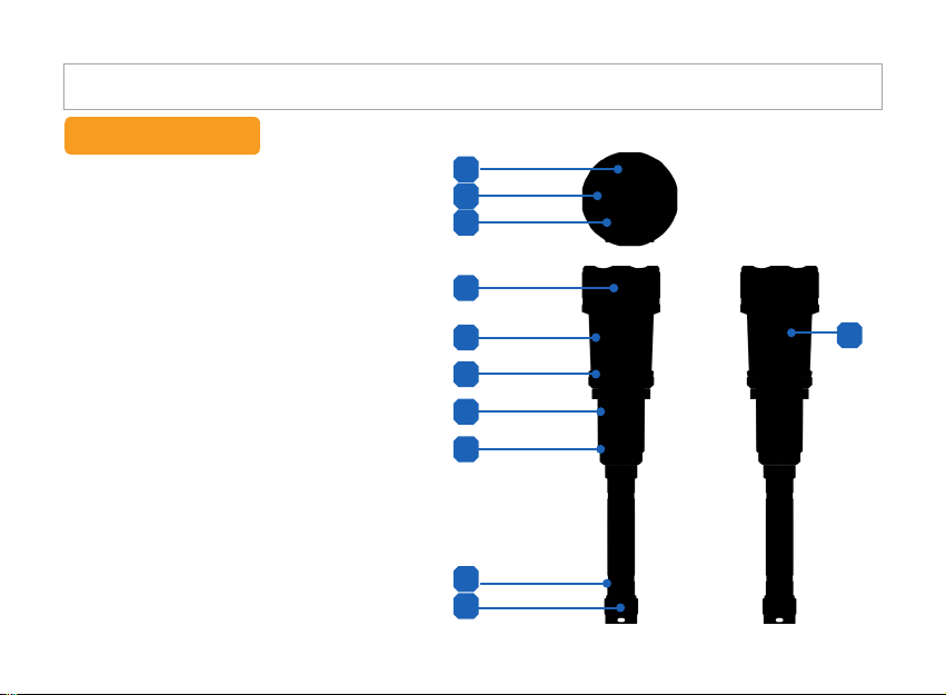
Parts name
1. Camera
2. IR LED (6pcs)
3. Hi Powered LED
4. Head
5. LCD Display
6. DVR Rotary Switch
7. Function Keys / GPS Receiver
8. LED Rotary Switch
9. Battery Cap
10. Slot for Hand Strap
11. Interface Out
(HDMI / USB / Micro SD Card)
10
1
2
3
4
5
6
7
8
9
- 4 -
LED Flashlight DVR User's Manual
11
Page 10
Before Operation
Battery Charging
Put the battery pack into the battery case as shown in illustration.
※
Caution
Use only authorized battery supplied what has 18650 PCM safety circuit inside.
Before insert the battery, conrm the battery polarity.
To charge batteries, put the battery case into battery
charger as shown in illustration.
Red LED : Under charging
Green LED : Charged completely
Red LED blink : Change battery (Normally life time of
battery pack is more than 500 times).
※
How to use and charge Lithium – ion Batteries
1, Use 2 battery packs in turn.
2. Do not leave fully charged battery (Green LED) in the charger more than 1 hour.
3. To prolong the battery life time, let the battery be full-discharging and full-charging once a half year.
4. It takes 5~6 hours to fully charge up a fully discharged battery.
5. Overcharging, over-discharging and charging below 0°C will shorten the battery life time and not
recommended.
- 5 -
Adaptor jack Battery Pack
Charger Cradle
Page 11
LED Flashlight DVR User's Manual
Check point for Waterproof function
Check carefully followings when use waterproof function.
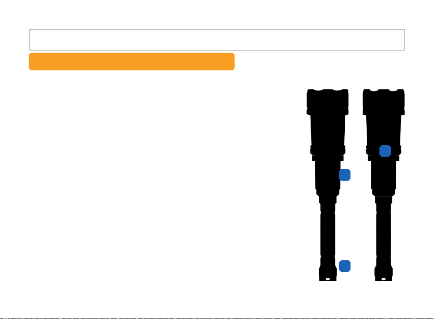
1. Check the waterproof ring(2pcs) completely which are installed on functional
key part(No.1), If it is damaged, replace waterproof ring(Key Control Section
O-Ring) supplied and spray lubricant on the O-ring.
2. Check the waterproof ring(2pcs) completely which are installed on Interface
part(No.2), ), If it is damaged, replace waterproof ring(Key Control Section
O-Ring) supplied and spray lubricant on the O-ring.
3. Check the waterproof ring(2pcs) completely which are installed on battery cap,
If it is damaged, replace waterproof ring(Key Control Section O-Ring) supplied
and spray lubricant on the O-ring.
4. Each waterproof cap should be closed completely.
5. Insufcient lubricant may cause of damage to waterproof ring.
[※ Caution]
1. Spray lubricant on every waterproof ring before using under the water.
(Insufcient lubricant may cause of damage to waterproof ring.)
2. Once waterproof cap for interface is installed, sound recording is not available
because mike hole is located in interface part.
3. Once waterproof cap for functional key part is installed, GPS receiving is not
available because GPS antenna is located in interface part.
4. Clean with water and dry up completely after using in the marine.
(Use rubber cap for interface and functional key part when normal operation)
5. To keep the waterproof performance completely, replace waterproof ring
one or two times per year.
(Four or ve times per year when frequently used)
6. Be careful not to be tapped foreign substances around waterproof ring.
7. Do not use more than 1 hour consecutively in the marine.
- 6 -
2
1
3
Page 12
Basic Functions
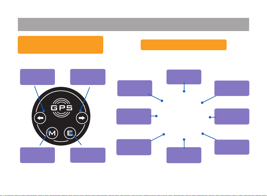
Function Keys/ GPS
Receiver
Zoom Out/
Left Key
Main Menu Enter
Zoom In /
Right Key
GPS &
E-Compass
System
Set-up
Video System
- 7 -
Main Menu
Video
Photo
Play Back
Time Zones
Photo System
Page 13
Operation
Flashlights
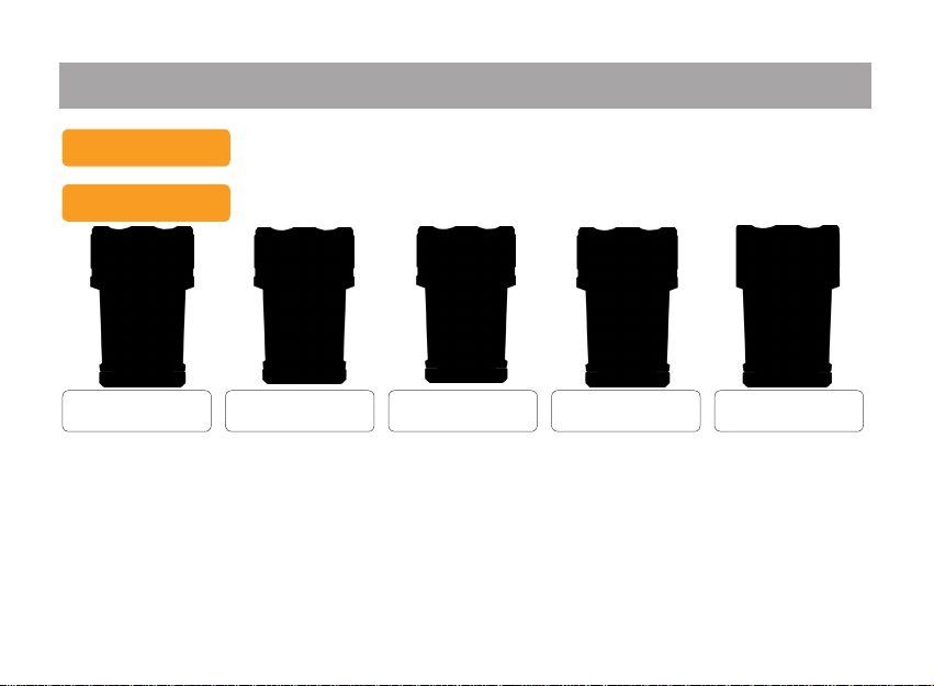
1. Flashlight is activated by LED rotary switch.
Each function is executed when icon on the rotary switch is placed on arrow marking.
Icons
SOS mode
100% Brightness Flashlight OFF 50% Brightness
- 8 -
Page 14
Operation
Video
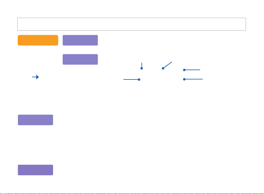
1. Activate Power On, Power Off and DVR recording with rotary switch .
Each function is executed when icon on the rotary switch is placed on arrow marking.
Icons
Night Vision
Video Recording
[※ How to change night vision mode and normal mode]
Night vision mode is activated when the rotary switch is set to "O N " icon on the right side of the "OFF" icon.
To activate Normal mode, rotate the switch to the opposite direction, set the other "ON" icon on the
arrow marking.
IR LED is turned on automatically in the Night vision mode.
Keep the ashlight OFF when IR night vision ON
In Night vision mode, it is available to take a photo or record video up to max 15M distance under
darkness (0.001 Lux). It shows light green color screen.
Night Vision
Power On
Power Off
- 9 -
Normal Mode
Power On
Normal Mode
Video Recording
Page 15
LED Flashlight DVR User's Manual
Video
DVR on
Stand by
GPS is under connection
Connected (GPS information is to be
stored when satellite is connected only)
Recording
DVR off
2. Video recor d in g i s s t ar t ed when rotary switch is placed on recording mode.
(Reco r di n g i s s to p pe d a n d its file is stored in the micro SD card inside once
return Power On mode back.)
Zoom In and Out functions are available using left & right direction keys.
[Remarks]
Zoom In & Out function is only a v ai l ab l e o n t he be l ow level of Full HD mode
(1920*1080).
GPS function is not available when waterproof cap for functional key is installed.
3. Set the rotary switch to OFF mode.
1. Set the rotary switch to proper "ON" position (Normal / Night vision).
Video Recording Mode
- 10 -
Available recording time
Battery status
Video Resolution
Page 16
Operation
Photo
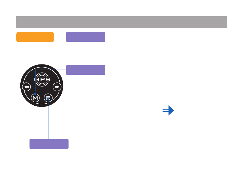
Take a photo
DVR on
Select Menu
3. Press “E” button to take a photo and it is stored automatically.
Zoom In & Out is available using left & right direction keys.
GPS and Zoom In & Out functions are not available
when waterproof cap for functional key is installed.
1. Set the rotary switch to proper "ON" position (Normal /
Night vision).
2. Press the "M" button to display main menu, select the
photo icon using left & right direction keys.
Then press “E” button to start photo mode.
- 11 -
Page 17
LED Flashlight DVR User's Manual
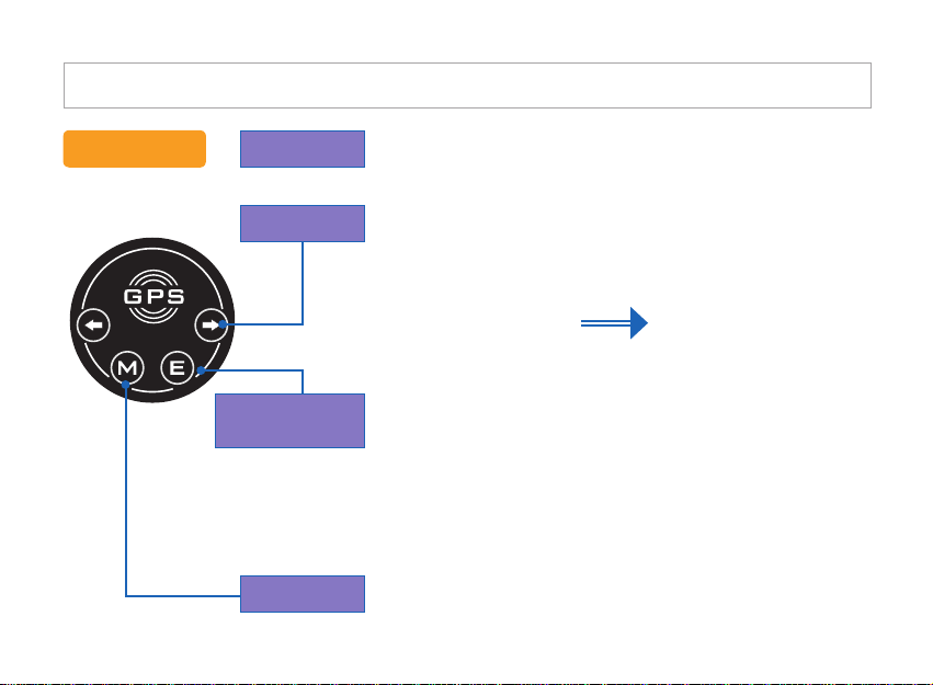
Play Back
DVR on
Select Menu
File selecting
Play back
Return
1. Set the rotary switch to any "ON" position.
2. Press the "M" button to display main menu, select the play
back icon using left & right direction keys.
Then press “E” button to start play back mode.
3. Select video le mode or photo le mode using left & right
direction keys and Press “E” button. Press “E” button again
after selecting video or photo le. The le will be activated.
4. Press “M” button to return upside menu.
- 12 -
Page 18
Operation
Time Zones
DVR on
Select Menu
Select & Execution
[※ How to set Time Zone]
In case of the eastern hemisphere : Set up with standard time
Ex : Korea is adapted on UTC +9, so its time zone is xed with 0009
In case of the western hemisphere : Set up with 24 + standard time
Ex : Los Angeles is adapted on UTC -8, so its time zone is xed with 0016
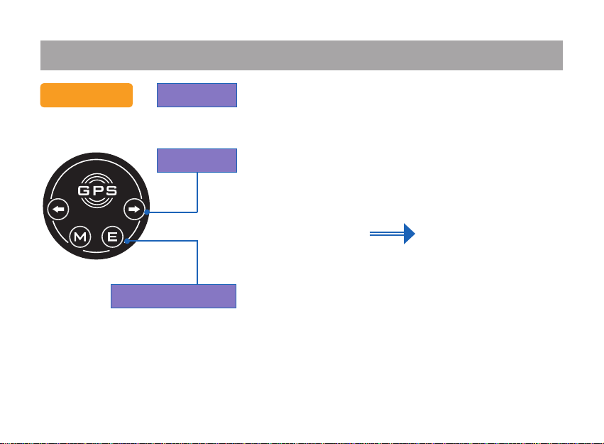
1. Set the DVR ON mode and then press [M] button to enter
the main MENU.
2. Select [Time Zone Setting] menu using left & right direction
keys
3. Select the Time Zone needed using left & right direction
keys and then press [E] button.
- 13 -
Page 19

LED Flashlight DVR User's Manual
Set up Time Zones
UTC + 14 Kiribati
UTC + 13 Tonga / Kiribati
UTC + 12 Nauru / New Zealand / Russia
UTC + 11 New caledonia / Russia / Federated States of Micronesia/ Vanuatu / Solomon Islands
UTC + 10 Australia (EST) / Papua New Guinea/ Russia
UTC + 9 South Korea / Russia / Indonesia (EST) / Japan / North Korea
UTC + 8 China / Malaysia / Mongolia / Russia / Singapore / Australia (CST) / Indonesia (CST) / Philippines
UTC + 7 Laos / Russia / Vietnam / Indonesia (WST) / Cambodia / Thai
UTC + 6 Russia / Bangladesh / Bhutan / Sri lanka / Kazakhstan(EST)
UTC + 5 Russia / Uzbekistan / Kazakhstan / Kyrgyzstan / Tajikistan / Turkmenistan/ Pakistan
UTC + 4 Russia / Oman / Kazakhstan (WST) / Armenia
UTC + 3 Georgia / Russia / Madagascar / Saudi Arabia / Somalia / Sudan /Yemen / Uganda / Iraq / Kenya /
Kuwait / Tanzania
UTC + 2 Eastern Europe Standard / Greece / South Africa / Lebanon / Rwanda / Libya / Lithuania / Mozambique /
Bulgaria / Ukraine / Israel / Egypt / Finland
UTC + 1 Central Europe Standard/ Nigeria /Norway/Netherland / Denmark / Germany / Monaco / Sweden / Spain/
Albania / Austria / Italia / Central African republic/ France
UTC Western European Standard/ Republic of Ghana/ Morocco / Sahara Occidental / Spain / UK(GMT) / Portugal
UTC − 1 Cape Verde / Portugal
UTC − 2 Brazil – Islands in Atlantic Ocean
UTC − 3 Brazil / Argentina
UTC − 4 USA (EDT)
UTC − 5 USA (EST) / Brazil / Ecuador / Jamaica / Canada (EST) / Peru
UTC − 6 USA (CST)
UTC − 7 USA (MST)
UTC − 8 Mexico / USA (PST ) / Canada (PST)
UTC − 9 USA (AKST )
UTC − 10 USA (HST)
UTC − 11 Samoa
Reference of time zone setting
- 14 -
Page 20

Operation
Photo System
DVR on
Select Menu
Select / Conrm
1. Set the rotary switch to proper “ON” position.
2. Press the "M" butto n t o d i sp l ay ma i n menu, select the
Photo System icon using left & right direc tion keys. Then
press “E” button to show Photo System status.
3. Selec t p h o t o resolution using left & right direction keys,
then press “E” button to conrm.
- 15 -
Page 21
LED Flashlight DVR User's Manual
Video System
DVR on
Select Menu
Select / Conrm
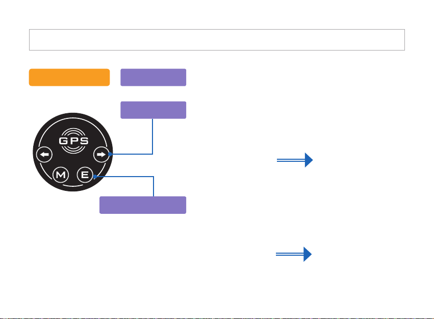
1. Set the rotary switch to proper “ON” position.
2. Press the "M" button to display main menu, select the
Video System icon using left & right direction keys. Then
press “E” button to show Video System status.
3. Select the resolution using left & right direction keys,
then press “E” button to conrm.
- 16 -
Page 22
Operation
System
DVR on
Select Menu
Select / Conrm
[※ Caution]
Whole le will be deleted once execute
Format so download les to the PC
before Format in the System.
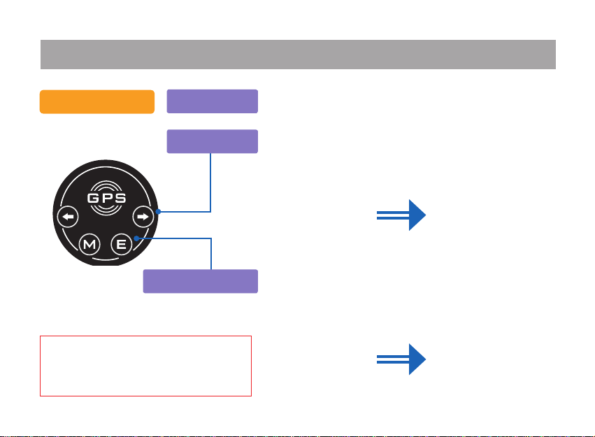
1. Set the rotary switch to proper “ON” position.
2. Press the "M" button to display main menu, select the System
icon using left & right direction keys. Then press “E” button
to show System status.
3. Select options using left & righ t d i re c ti o n k eys, t h en
press “E” button to show the setting. Press “E” button to
return to upper menu after selection.
- 17 -
Page 23
LED Flashlight DVR User's Manual
GPS / Compass
DVR on
Select Menu
Return
[Tip]
1. Real time GPS information is stored in the folder of [GPS INFO] in Micro SD card inside
whenever entering into the GPS MENU from the main menu.
2. Time setting is updated automatically when GPS is available.
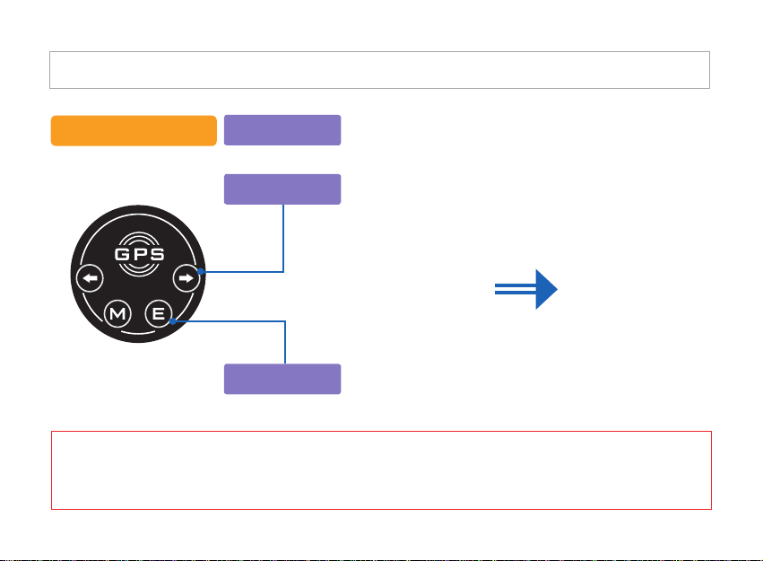
1. Set the rotary switch to “ON” position.
2. Press the "M" button to display main menu, select the
GPS Compass icon using left & right direction keys.
Then press “E” button to show GPS Compass status.
3. Press “M” button to return to main menu.
- 18 -
Page 24

PC Viewer Instruction
1
Install PC Viewer
Conrm the Micro SD card and reader inside the carrying
case as shown in illustration.
Connect Micro SD card reader to your PC or laptop and nd
PC viewer folder.
Copy the folder into your PC or laptop.
Open the PC Viewer folder and install this program clicking SETUP.EXE le.
Step 1
Run the SETUP.EXE le.
- 19 -
Page 25

LED Flashlight DVR User's Manual
Step 2 Step 3
Click [NEXT]
Input user information and click [NEXT]
-20 -
Page 26

PC Viewer Instruction
Step 4 Step 5
Select the folder where the program is to be
installed and click [NEXT] If you do not select
the folder, the program is to be installed in C:\
Program les\Pharobit \Pharobit automatically.
Mark “ffdshow” once you do not have
MP4(H .264) codec in your PC . Mark
“Window Med ia player 11” if you do not have
it in your PC. This page is not shown in the
higher O/S version than Windows XP.
- 21 -
Page 27

Step 6 Step 7
Click [Finish] after installationClick [Install]
- 22 -
LED Flashlight DVR User's Manual
Page 28

PC Viewer Instruction
Step 8 Step 9
Select the language to install multi codec
once you mark “ffdshow” in the step 5
Click [NEXT] to install
- 23 -
Page 29

Step 10 Step 11
Click [NEXT] to installSelect the folder to install codec. If you do not
select the folder, the program is to be installed in
C:\Program les\ffdshow automatically.
- 24 -
LED Flashlight DVR User's Manual
Page 30

PC Viewer Instruction
Step 12
Click [NEXT] to install . Click [NEXT] to install
Step 13
- 25 -
Page 31

Step 14 Step 15
LED Flashlight DVR User's Manual
Click [Install]
Click [Finish] after installation
- 26 -
Page 32
PC Viewer Instruction
Step 16
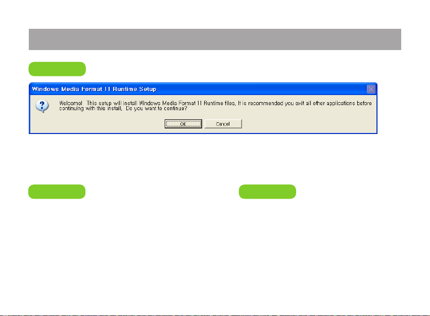
“Windows Media Player” install window is popping up once you mark “Windows Media
Player” in the step 5. Click [Yes] to install.
Step 17 Step 18
Click [Yes] once you agree the license
Click [OK] to complete
- 27 -
Page 33

LED Flashlight DVR User's Manual
1
3 4
5
7 8 9
12
13
14
6
2
10
11
2
PC Viewer display
1. Pharobit LOGO
2. Minimize, Maximize, Close
3. Video screen
4. Map screen
5. Map / satellite view selection
Run the PC Viewer.
6. Play, Stop, REW, FF, Mute,
Repeat control, Volume bar
7. File Search
8. Maximize Video Screen
9. Maximize Map Screen
- 28 -
10. Video edition start button
11. Video edition nish button
12. File manager
13. File list
14. Total distance display
Page 34

PC Viewer Instruction
File Sear ch
3
To play video le, click the le search icon and select a *.MP4 le in the browser.
To see GPS data on the map only, select a *.TXT le in the browser.
File Search
MP4 / TXT selection
File path : SDCARD root\DCIM\100MEDIA
※
Caution
1. Video screen is not available when open TXT le.
2. Map Screen is not available if no TXT le exists with
same le name to the selected MP4 le.
3. Map Screen is not supported without Internet access.
Screen for Selecting TXT le
- 29 -
Page 35
LED Flashlight DVR User's Manual
Display whole
distance
File name in Playing
4
Global position information
Red balloon pins pop up during video playing which have GPS information. Global position, time,
path and distances are displayed once a red balloon pin is clicked.
- 30 -
Page 36

PC Viewer Instruction
5
User path creation
1. Right click on a red balloon pin, where the origin,
then “add ruler” menu pops up.
2. Click t h e “ a d d r u l e r ” menu and a yellow point
marker is created.
3. Drag the marker to an arbitrary user point.
Distance fro m the ori g i n to the user point is
displayed automatically .
It is p o s s i b l e t o m a k e a new user point from the
user point, then it displays total d is ta nc e fr om
origin red balloon pin through the user points.
This function is useful to measure distance through
arbitrary path.
Start point of recording : Blue balloon pin
Path Tracing : Red balloon pin
Finish point of recording : Green balloon pin
Created random post : Yellow balloon pin
- 31 -
Page 37

LED Flashlight DVR User's Manual
Delete
Button
Stor e
Button
File history
File manager
6
Store user path
Store user path by clicking “File manager” button (No.12) followed by “Map save” button.
- 32 -
Page 38

PC Viewer Instruction
Start time
thum bna il image
End time
thum bna il image
Edit Video7
This function allow users to create new video les from a video le by specifying video start and end points.
1. Move the time slide bar to the time where the new video le supposed to be started, or play the
le until the time.
2. Click video edition start button (10), then a window pops up with the thumbnail image of the start time.
3. Play the le again, or move the slide bar until the end time and then click video edition nish
button (11). The thumbnail image of the end time is displayed on the blank on the right side of the
start time thumbnail image.
4. Create a new video le by clicking save button.
10 11
- 33 -
Page 39

Q & A
Can not turn on the device?
● Check if the battery is installed as instructed in the manual.
● Check the battery power
Recording is not available?
● Do not insert the Micro SD card while DVR is turned on.
The card should be installed while DVR is turned off.
● Check the memory capacity left.
● Audio recording is not available once the waterproof cap for interfaces is installed.
LCD does not turn on?
● Check it the rotary switch is placed on “ON” position.
● Check the battery power.
● Set to the night vision mode in the night.
The map is not available in the PC Viewer?
● Check the internet connection.
● If the GPS information is not stored, the map is not working in the PC Viewer.
● GPS inaccessible area: Inside buildings, Underground parking lots, Complex skyscraper area,
Bad weather conditions etc.,
- 34 -
Page 40

Specication
Image Sensor 5M Pixel Color CMOS Sensor
LED Lamp SSC P7 LED
Display 1.5” TFT LCD
GPS SiRF Star IV High Performance GPS Chipset
Night-Vision Auto Digital IR–Cut Shift Module (6EA 850nm IR LED)
Waterproof IP 68 (Max 100M) with Sealing Caps tted
E- Compass Magnetic Sensor Type
Control Switch Twin LED & DVR Magnetic Rotary Switch
Housing Aircraft Aluminum 6061 T6 , Hard Anodizing Heat Treatment , Pyrex Lens
White Balance Auto
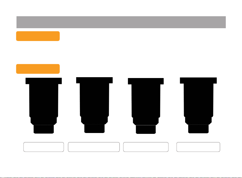
Recording Frame Rate 1920×1080 (30fps) , 1280×720 (30fps) , 848 ×480 (60fps) , 640 × 480 (30fps)
Image Resolution 4000×3000 , 3200×2400 , 2592x1944 , 2048x1536
Voice Recording HQ AAC INCORDER (In the Water Cannot be Recorded)
LED Lamp Life (white) SSC P7 Provide More than 100,000 Hours of Trouble Free Life. Max 900 Lm
Brightness 2-Levels of Brightness and SOS Signal
OSD and System Menu Display Include Monitoring Viewnder
OSD Language Display English, Korean and other selectable options
Recording Media TF Card, Max 32GB (Max 16Hr)
Interface USB , MINI HDMI , TF Card slot
Battery Operable 2 x 18650 LI-ION Battery
Battery Run Time(MAX) 4.5 Hours Flashlight Only. - 3.5 Hours (Camera and Flashlight)
Size & Weight 375mm x 80mm(Max Diameter), 980g (Without Battery)
(Visual Distance 300m)
- 35 -
Page 41

FCC INTERFERENCE STATEMENT
gpp g
accordance with the instructions, may cause harmful interference to radio communications. However, there is no guarantee
FCC ID : AZLGCF-200
The users manual or instruction manual for an intentional or unintentional radiator shall caution the user that changes or
modifications not expressly approved by the party responsible for compliance could void the user's authority to operate the
equipment. In cases where the manual is provided only in a form other than paper, such as on a computer disk or over the
Internet, the information required by this section may be included in the manual in that alternative form, provided the user can
reasonably be expected to have the capability to access information in that form.
For a Class B digital device or peripheral, the instructions furnished the user shall include the following or similar statement,
placed in a prominent location in the text of the manual:
NOTE: This equipment has been tested and found to comply with the limits for a Class B digital device, pursuant to Part 15
of the FCC Rules. These limits are designed to provide reasonable protection against harmful interference in a residential
installation. This equipment generates, uses and can radiate radio frequency energy and, if not installed and used in
that interference will not occur in a particular installation. If this equipment does cause harmful interference to radio or
television reception which can be determined by turning the equipment off and on, the user is encouraged to try to correct the
interference by one or more of the following measures :
- Reorient or relocate the receiving antenna.
-Increase the separation between the equipment and receiver.
- Connect the equipment into an outlet on a circuit different from that to which the receiver is connected.
- Consult the dealer or an experienced radio, TV technical for help.
- Only shielded interface cable should be used.
*Caution : Any changes or modifications in construction if this device which are not expressly approved by the
party responsible for compliance could void the user’s authority to operate the equipment.
-36-
 Loading...