

Page 1
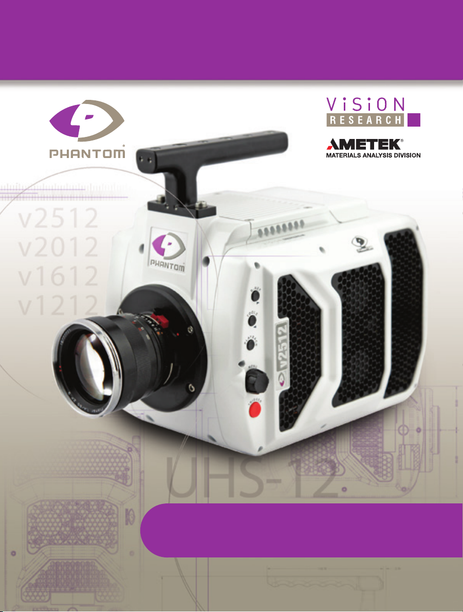
PHANTOM
Ultrahigh-Speed Cameras
v2512 / v2012 / v1612 / v1212
MANUAL
When it’s too fast to see, and too important not to.
v2512, v2012, v1612, v1212 GETTING STARTED MANUAL ZDOC-64110-MA-0001 Rev 1
®
Page 2

w w w . v i s i o n r e s e a r c h . c o m
Phantom Ultrahigh-speed Camera Manual
PN: ZDOC-64110-MA-0001 Rev 1
Last updated: 10.19.2015
Page 3

when it’s too fast to see, and too important not to.
Phantom Ultrahigh-
speed cameras
MANUAL
®
100 Dey Road
Wayne, NJ 07470 USA
+1.973.696.4500
phantom@visionresearch.com
www.visionresearch.com
Page 4

w w w . v i s i o n r e s e a r c h . c o m
Written and produced by the Marketing Department at Vision Research.
The contents of this manual are subject to change without notification.
PN: ZDOC-64110-MA-0001 Rev 1
Last updated: 10.19.2015
Page 5

Contents
Introduction
1
Quick Start Guides
2
Phantom Software
3
Download & Image Processing
4
Measurements
5
On-Screen Displays
6
Phantom CineMag & CineStation IV
7
Phantom Remote Control Unit (RCU-2)
8
Support
9
1
9
17
31
35
45
57
63
65
Phantom Ultrahigh-speed Camera Manual
Page 6

v2512 v2012 v1612 v1212
Max. Speed
25,600 fps at
full resolution
1280 x 800;
1,000,000 fps at
reduced resolution
of 128 x 32
w/FAST option
(677,000 w/o)
22,0000 fps at
full resolution
1280 x 800;
1,000,000 fps at
reduced resolution
of 128 x 32
w/FAST option
(666,000 w/o)
Min. Speed
Pixel
Sensitivity
Monochrome: 32,000D (Daylight)*; 100,000T (Tungsten)
CAR
features
Throughput /
Speed
Exposure
Exposure
in PIV
Memory
Trigger
25 Gpx/s /
25,000 fps
1 Gpx/s throughput Direct Record to Phantom CineMag IV
1 μs minimum
standard;
280 ns min w /
FAST option
375 ns 425 ns 400 ns 550 ns
72GB, 144GB, 288GB high speed internal RAM
CineMag IV non-volatile memory storage (1TB, 2 TB)
Dedicated BNC, via capture port, On-Camera Controls, Image-Based Auto-Trigger,
Options
Ethernet
Power
Video Out
Special
Standard Gb Ethernet and 10Gb Ethernet for faster download speed
Two ports for primary and backup (20-28 VDC) on camera back panel
Two HD-SDI ports on camera; Analog video (NTSC or PAL) available on Break-out-Box;
Partition memory into segments and make shorter recordings back-to-back without
Internal mechanical shutter for hands-free and remote CSR
Features
Advanced ‘On-Camera Controls’ for camera setup, capture, playback, edit,
Popular
Accessories
* Measured according to ISO 12232:2006 method
CineMag IV, CineStation IV for CineMag IV, RCU, Break-out-box,
Video monitor for use with on-camera controls
28 μm size, 12-bit depth
Color: 6,400D*; 10,000T*
128 x 16 (Continuous Adjustable Resolution)
20 Gpx/s /
20,000 fps
1 μs minimum
standard;
305 ns min w /
FAST option
or via Phantom PCC software
Component viewfinder port
missing any action (63 maximum)
(Current Session Reference)
and save to Phantom CineMag IV
16,000 fps at
full resolution
1280 x 800;
1,000,000 fps at
reduced resolution
of 128 x 16
w/FAST option
(647,000 w/o)
100 fps
16 Gpx/s /
16,000 fps
1 μs minimum
standard;
500 ns min w /
FAST option
12,000 fps at
full resolution
1280 x 800;
820,000 fps at
reduced resolution
of 128 x 16
w/FAST option
(571,000 w/o)
12 Gpx/s /
12,000 fps
1 μs minimum
standard;
500 ns min w /
FAST option
Phantom Ultrahigh-speed Camera Manual
Page 7
1
Introduction
Camera Capabilities
The Phantom ultrahigh-speed UHS-12 Series consists of
the v1212, v1612, v2012, v2512.
The Phantom v1212 digital high-speed camera is capable
of capturing 12 Giga-pixels per second (Gpx/s) of data
from our proprietary CMOS sensor. At full resolution
(1280 x 800), the camera can capture 12,000 framesper-second (fps).
The Phantom v1612 features 16 Gpx/s throughput and
a maximum frame rate of 16,000 fps at full resolution
(1280 x 800).
The Phantom 2012 achieves over 22 Gpx/s throughput
and a maximum frame rate of 22,000 fps at full resolution
(1280 x 800).
The Phantom 2512 boasts 25 Gpx/s throughput and a
maximum frame rate of more than 25,000 fps at full
resolution.
1
Chapter 1: Introduction
Page 8

All Ultrahigh-speed cameras are capable of over 570,000
fps at reduced resolution. The FAST option (export
controlled), available for all ultra high-speed cameras,
increases frame rates to 800,000 fps for the Phantom
v1212 and 1,000,000 fps for the Phantom Phantom
v1612, v2012, and v2512 camera models.
High throughput is important. At any given resolution,
a camera with the highest throughput will provide the
fastest possible frame rates.
Image Storage
Sensor Characteristics
The Phantom v1212, v1612, v2012, and v2512 cameras
can be equipped with 72GB, 144GB, or 288GB of highspeed memory. A camera with 288GB of memory,
recording at 10,000 fps at 1280 x 800 can record
a single high-speed shot (called a cine) for almost 20
seconds.
The Phantom v1212, v1612, v2012, and v2512 cameras are also compatible with Phantom CineMag IV long
recording devices available in 1TB and 2TB capacities.
The Phantom v1212, v1612, v2012, and v2512 cameras
can securely save a 288 GB cine to an attached Phantom
CineMag IV in about 4.5 minutes. (Phantom CineMag IV
throughput is 1GB/s for these cameras).
The Phantom v1212, v1612, v2012, and v2512 use a
proprietary CMOS sensor designed by Vision Research
and are available in monochrome or color versions.
Their 28 micron (μm) pixels result in very high light
sensitivity. All UHS-12 Series monochrome cameras have
a sensitivity of ISO 32,000D* and 100,000T, and color
cameras ISO 6,400D* and 10,000T*
Sensor resolution is 1280 x 800 pixels “wide-screen”
format. The rectangular shape of the 1 Mpx sensor allows
the user to keep moving objects in the frame longer and is
compatible in aspect ratio with modern display technology.
The physical size of the sensor is 35.8mm x 22.4mm
(42.27mm diagonal).
2
Phantom Ultrahigh-speed Camera Manual
*: Measured using the ISO 12232 SAT method.
Page 9

All Phantom Ultrahigh-speed cameras have global
electronic shutters, with minimum exposure times of
1μs (standard). With the (export controlled) FAST option
minimum exposure times are: v2512 - 280ns, v2012 3015ns, v1612 - 500ns, v1212 - 500ns.
Advanced Features
Image-Based Auto-Trigger (IBAT): Phantom v1212,
v1612, v2012, and v2512 cameras can detect changes
in an image which can be used to trigger the camera
(or even a number of cameras), making it easy to record
unpredictable events.
Multi-Cine: The internal memory of a Phantom v1212,
v1612, v2012, and v2512 camera can be partitioned into
as many as 63 segments for shorter recordings, back-toback, without missing any action.
Burst Mode: Precisely generate a programmable
number of frames for every (internal or external) frame
synchronization pulse.
Internal Mechanical Shutter: Easily perform black
references remotely using the built-in mechanical capping
shutter for optimum image quality.
10Gb Ethernet: 10GBase-T (RJ45) Ethernet port for very
fast data transfer.
Continuous Recording: Automatically save cines from
internal camera memory to an external storage, without
user intervention.
Exposure in PIV: The Phantom Ultrahigh-speed cameras have an extremely short inter-frame (straddle) time,
(the Phantom v2512 is 375ns, the v2012 is 425ns, the
v1612 is 400ns, and the v1212 is 550ns), and are easily
synchronized with external devices.
Command & Control
All Phantom ultra-high speed cameras can be setup and
controlled using the built-in On-Camera Controls (OCC),
the user-friendly Phantom Camera Control (PCC) software,
or a Phantom Remote Control Unit (RCU).
Detailed information about Phantom cameras,
features, and software can be found at:
www.visionresearch.com
3
Chapter 1: Introduction
Page 10

on-camera controls
4
Phantom Ultrahigh-speed Camera Manual
Page 11

PLAYBACK
On-Camera Controls (OCC) provide full control of the
camera without the need to connect to a PC.
B-REF - when the camera is ‘Live’ and ‘Waiting for
Trigger’ this button initiates a Black Reference.
During ‘Playback’, it is the Play, Pause, or Fast Forward
(hold 1 sec) button.
Tools - when the camera is ‘Live’ and ‘Waiting for Trigger’
this button toggles between a Live image, and the Zoom,
and Threshold functions.
During ‘Playback’, it is the Rewind, Pause, or Fast Rewind
(hold for 1 sec) button.
Playback - used to select a cine for playback
(from internal memory / Phantom CineMag IV).
Menu - used to display the Setup menu and to navigate /
select recording parameters.
During ‘Playback’, it can be used to select, edit, save,
or scroll (scrub) through cines.
Trigger - used to:
• Switch from ‘Pre-trigger’ to ‘Waiting for Trigger’
• Trigger the camera (‘Loop’ mode)
• Start (hold 1 sec) / Stop recording
(‘Run/Stop’ mode)
• Return to ‘Live’ mode
Using the Menu Knob
1. From any of the ‘Live’ screens; rotate the Menu
knob to display the ‘Camera’ menu
2. Rotate the knob to the desired camera parameter,
then press the knob to select
3. Rotate the knob, in either direction, to change the
selected parameter, then press knob to confirm
5
Chapter 1: Introduction
Page 12
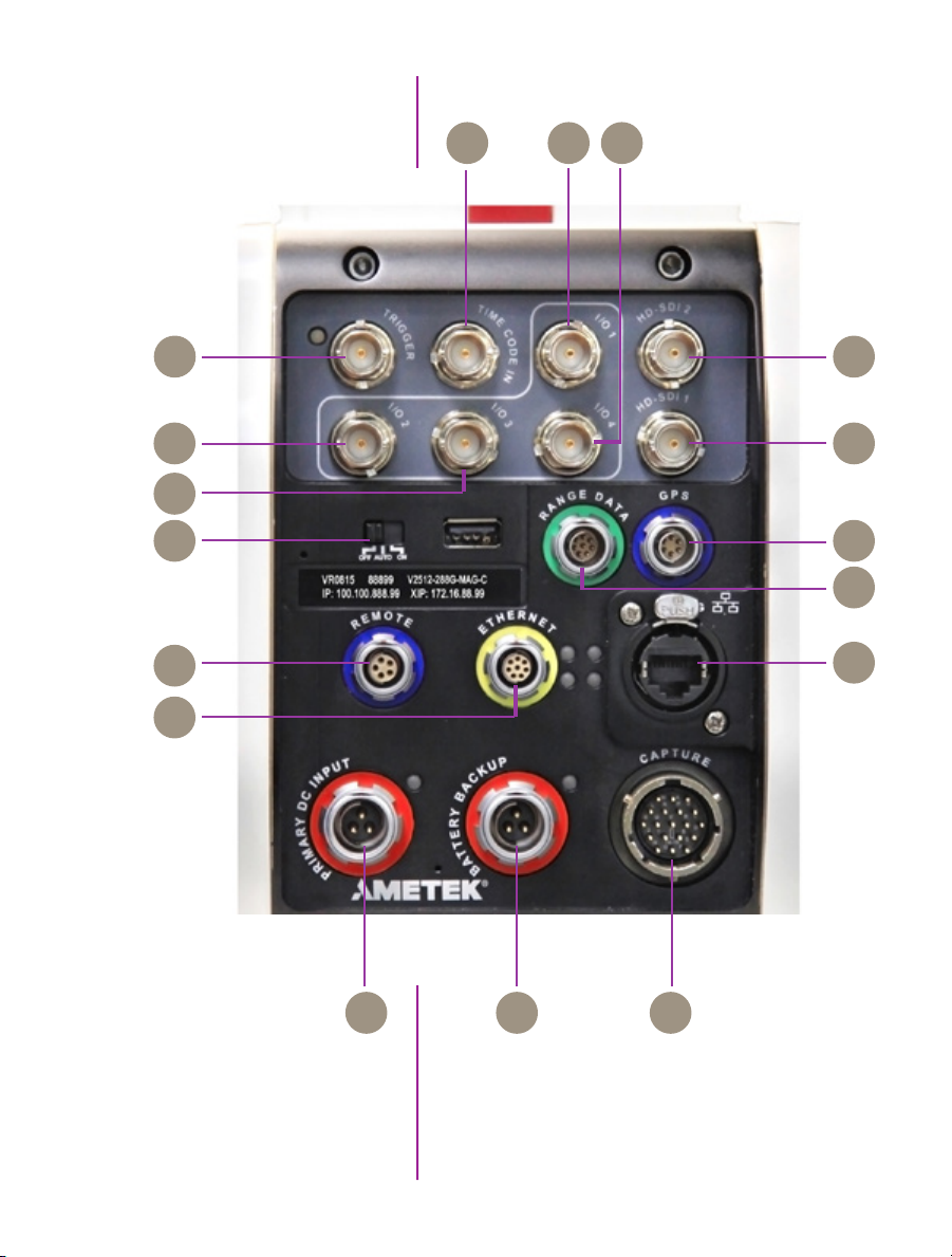
B C F
A G
D
E
L
M
H
I
O P Q
K
J
N
rear connector panel
6
Phantom Ultrahigh-speed Camera Manual
Page 13

Trigger
TTL Pulse (Rising/Falling Edge), Switch Closure
A
Time Code In
I/O 1
I/O 2
I/O 3
I/O 4
HD-SDI 2
HD-SDI 1
Power Switch
Range Data
GPS
Remote Control Port
IRIG-B In (Modulated/Unmodulated)
B
Ready
C
F-Sync
D
Time Code Out: IRIG-B, SMPTE
E
Strobe
F
The two HD-SDI ports can acts as identical 4:2:2
G
HD-SDI ports with one set up to provide an optional)
on-screen display to monitor the on-camera controls
H
and cameaa operation. Or, they can be configured as a
‘single 4:4:4 Dual-Link HD-SDI port.
Off / Auto / On
I
Used to stamp images with acquisition data (azimuth
J
and elevation)
GPS input for GPS timing, longitude & latitude
K
RS-232 and Power (for Phantom Remote Control)
L
1 Gb Ethernet
10 Gb Ethernet
Primary DC Input
Backup DC Power
Capture Port
CAT5 UTP (for control and data transfer)
M
RJ45 10Base-T UTP (for control and data transfer)
N
20 - 28 Volts DC
O
20 - 28 Volts DC Backup
P
Ready, Strobe, A-Sync, Pre-trigger, NTSC/PAL Video
Q
7
Chapter 1: Introduction
Page 14
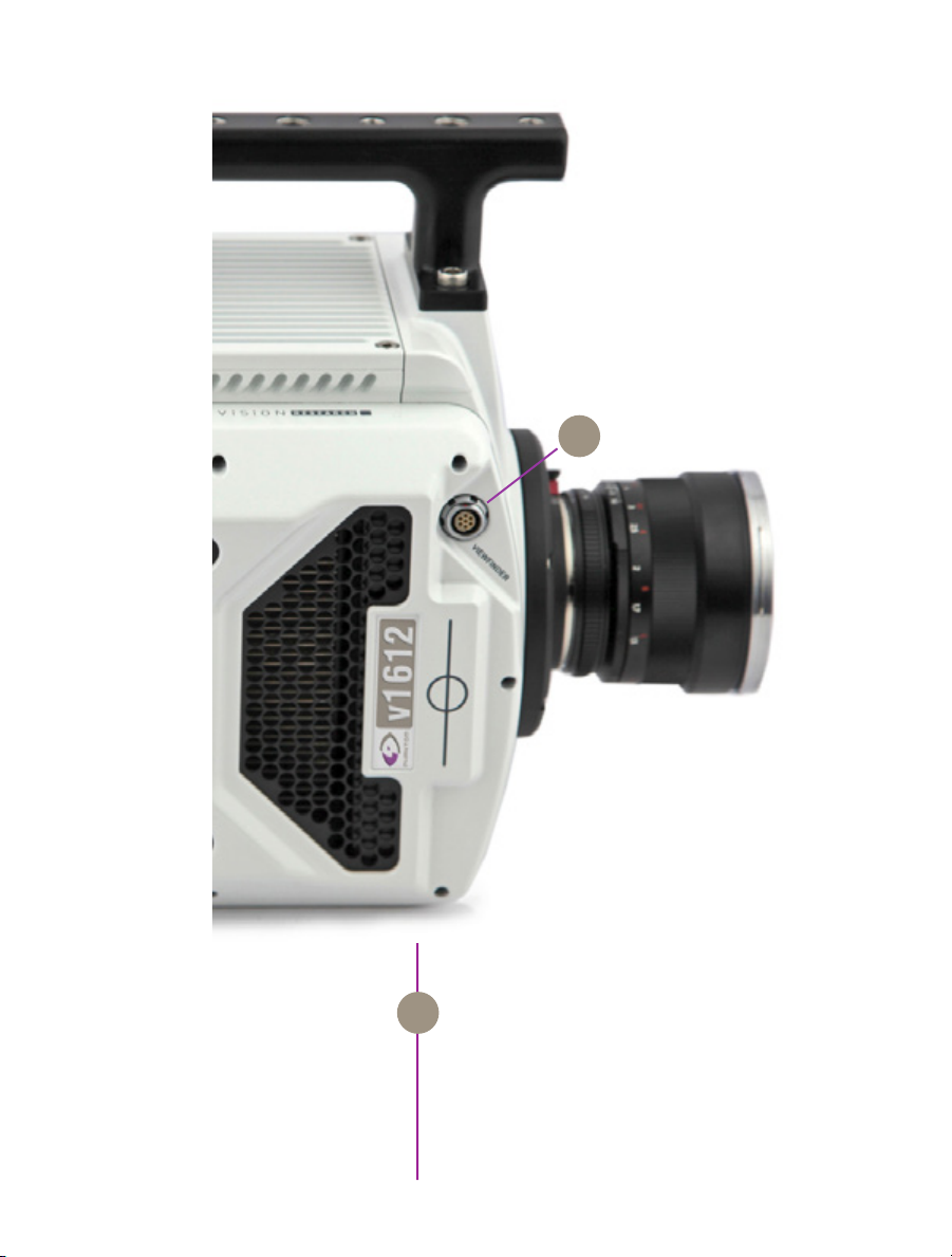
A
side connector
7-pin Fischer – Provides +12V power and component
VF Pwr or Component VF
A
signal for viewfinders such as the Sony HDVF35W.
Also works with the Phantom YPRPB cable.
8
Phantom Ultrahigh-speed Camera Manual
Page 15

2
Quick Start Guides
Prepare Your Computer
Install PCC Software
Connect the Camera to
the Computer
via pcc software
Camera controlling computers:
1. Must have either the Microsoft Windows XP Pro,
VISTA Business Edition or Windows 7 or
8 operating system installed.
2. Firewalls must be turned off.
(Contact your IT Group if necessary)
3. Using the ‘Windows Control Panel’ set the IP
address of your computer’s network card to
100.100.100.1 with a 255.255.0.0 subnet mask.
4. If working with a 10Gb Ethernet connection the
computer’s IP address should be set to 172.16.0.1
with a 255.255.0.0 subnet mask.)
Install the latest version of Phantom Camera Control
(PCC) software from the accompanying CD or USB key.
Connect the 20 - 28 VDC power supply to the camera’s
Primary DC Input connector.
Attach the supplied Ethernet cable between the Phantom
camera and the computer.
Connect the supplied Capture cable to the Phantom
camera.
Attach Phantom CineMag IV
If an external trigger is being used to trigger the camera,
connect it to Trigger connector on the rear panel of the
camera.
Mount a Phantom CineMag IV, if available.
Detailed information about attaching a Phantom
CineMag IV can be found in Chapter 7: Phantom
CineMag & CineStation IV of this manual.
9
Chapter 2: Quick Start Guides
Page 16

Select Camera for Use
In the Manager Control Panel double mouse-click on the
Phantom camera to be used from the ‘Cameras’ group
folder.
Define Recording
Parameters
‘Arm’ Camera
Trigger
Click the ‘Live’ tab.
Click ‘Cine Settings’ and define following parameters by
either the selecting the required value from the pull-down
selection list, or type a value into the respective data entry
field.
1. Set ‘Resolution’ to the required Width x Height.
2. Choose the required ‘Sample Rate’ and ‘Exposure
Time’.
3. Ensure the EDR, (Extreme Dynamic Range)
exposure time is set to zero (0).
4. Post Trigger to zero (0) by:
e. Moving the ‘T’ (Trigger Position) slider to the
right, or
f. Enter zero (0) into the ‘Last’ data entry field.
Click on the CSR button to perform a Current Session
Reference.
Click the ‘Capture’ button to start recording to the camera’s internal memory (circular buffer).
At the end of the action, click the action ‘Trigger’ button
at the bottom of the ‘Live’ panel, or
10
Phantom Ultrahigh-speed Camera Manual
Edit Cine
Provide a switch closure or an external trigger signal
(TTL pulse) via the Trigger connector.
Click the ‘Play’ tab.
Using the following Video Control Buttons to locate the first
image of the cine to be saved.
Rewind
Pause
Play
Fast Rewind
Rewind 1 Frame
Advance 1 Frame
Fast Forward
Page 17

Locate the first image of the cine to be saved.
Click the ‘Mark-In button.
Locate the last image of the cine to be saved.
Click the ‘Mark-Out’ button.
Select ‘Play, Speed, & Options’ and enable (check) ‘Limit
to Range’.
Under the Video Control Buttons click the ‘Jump to Start’
button.
Review Edited Cine
Save to Computer
Save to Attached
Phantom CineMag IV
Review the edited cine using the Video Control Buttons.
Click the ‘Save Cine...’ button at the bottom of the ‘Play’
panel.
In the ‘Save Cine’ window:
1. Navigate to the folder where you want to save the
cine file.
2. Enter a file name for the cine file in the ‘File name:’
data entry field.
3. From the Save as type pull-down selection list
select the ‘Cine Raw, *.cine’ file format.
4. Click the Save button to begin downloading the
cine file from the camera to the computer’s hard
drive.
Click the down-arrow of the ‘Save Cine... button.
Select ‘Save RAM Cine to Flash’ (in popup window).
Click the Save button to save the cine file onto the
Phantrom CineMag IV.
Confirm cine save before deleting from
internal memory
11
Chapter 2: Quick Start Guides
Page 18

Confirm Computer Save
Click the ‘Open File’ button.
In the ‘Open Cine’ window:
1. Navigate to the folder containing the saved cine
file.
2. Highlight the cine file to be opened.
3. Click the Open button.
Using the Video Control Buttons review the saved cine file.
Confirm CineMag Save
Click the ‘Manager’ tab.
Double-click on the ‘Cine F#’ file under the camera used
to record the cine.
Using the Video Control Buttons review the saved cine file.
12
Phantom Ultrahigh-speed Camera Manual
Page 19

Mount camera onto suitable support.
Attach and adjust appropriate lens.
Power Up Camera
Setup Video Monitor
Attach Phantom CineMag IV
Set Recording Parameters
Connect a suitable power supply (20-28VDC) to the
Primary DC Input connector, then set the power switch
to the ‘ON’ position.
Connect a suitable HD-SDI video monitor (not supplied)
to the ‘HD-SDI 1’ connector on the connector panel of the
camera.
Mount a Phantom CineMag IV, if available. For detailed
instruction see Chapter 7: Phantom CineMag & CineStation IV.
From any of the ‘Live’ screens; rotate the Menu knob to
display the ‘1/2 Camera’ menu.
Rotate the knob to the desired camera parameter, then
press the knob to select.
Rotate the knob, in either direction, to change the selected
parameter, then press knob to confirm.
• Set ‘Resolution’ to the required Width x Height
• Choose the required ‘Speed’ (frame rate) and
‘Shutter’ (exposure time).
• Set the ‘T’ (trigger position) at the beginning, or the
end, or some position within the internal memory
Perform Black Reference
Press ‘B-REF’ button.
Black Reference should be performed after all
recording parameters have been set.
via on-camera controls
13
Chapter 2: Quick Start Guides
Page 20

Perform White Balance
(Color Cameras Only)
From the ‘1/2 Camera’ screen; rotate the ‘Menu’ knob
until the ‘2/2 Image’ screen displays.
Point camera towards a non-saturated white area.
Set ‘White Balance’ to ‘OK’, then press the ‘Menu’ knob.
Set ‘CC+0’ (Color Compensation) to ‘Auto’, then press the
‘Menu’ knob.
‘White Balance’ (Color Temperature) adjusts
the red and blue components, while ‘Color
Compensation’ adjusts the magenta and
green components of the white balance.
‘Arm’ Camera
Trigger
Select Cine
Edit Cine
Playback
Save to Phantom CineMag IV
Press the ‘Trigger’ button to switch from ‘Pre-trigger’ to
‘Waiting for Trigger’ (‘Loop’ mode).
Press the ‘Trigger’ button.
Press ‘Menu’ knob to access the ‘Select’ screen.
Rotate ‘Menu’ knob to the cine to be reviewed, then
depress to select it.
Press ‘Playback’ knob to access the ‘Play Options’ screen.
Locate the first image to be saved and select ‘Set In’ to
set the Mark-In point.
Locate the last image to be saved and select ‘Set Out’ to
set the Mark-Out point.
Review the edited cine.
‘Save’ marked frames to Phantom CineMag IV (optional).
Confirm save to Phantom CineMag IV before
deleting from internal memory
14
Phantom Ultrahigh-speed Camera Manual
Page 21

‘Connect Camera to
Remote Control Unit
Connect an HD (BNC) cable between the ‘Video-In’
connector on the rear of the Remote Control Unit (RCU),
and the HD-SDI 2 connector on the rear panel of the
camera.
Connect the Remote cable (9-pin female) to the ‘Remote’
connector on the rear of the RCU.
Connect the Remote cable (9-pin male) to the ‘Remote’
connector on the camera’s rear panel.
Power Up Camera
Power Up RCU
Install Phantom CineMag IV
Set Recording Parameters
Connect a suitable power supply (20-28VDC) to the
DC Input connector, then set the power switch to the
‘ON’ position.
Hold in the RCU ‘Menu’ button (2 seconds).
Insert a Phantom CineMag IV, if available. For detailed
instruction see Chapter 7: Phantom CineMag &
CineStation IV.
Gently depress the ‘Setup’ button, then the Acq,
(Acquisition), button.
Set the‘Aspect Ratio’: Press the down-arrow (right of
‘Aspect Ratio’ field) and select an ‘Aspect Ratio’ from
the pull-down selection list.
Define the Resolution, Frame Rate, Exposure, and Post
Trigger settings using the Numerical Keypad to specify
the desired setting.
To overwrite the present value:
1. Tap the entry field once, (turns entry field yellow),
then
2. Tap the key pad to enter the desired value.
3. Tap the Enter key to set the value.
To append the value:
4. Tap the entry field twice, (turns entry field white),
then
5. Tap the key pad to append the value.
via remote control unit
6. Tap the Enter key to set the value.
15
Chapter 2: Quick Start Guides
Page 22

Press the Return, , icon (upper-left) to return to the
Setup Screen.
Perform CSR
Perform White Balance
(Color Cameras Only)
‘Arm’ Camera
Trigger
Edit Cine
Press the ‘Capture’ button.
Tap the CSR, (Current Session Reference), button
When prompted tap the Begin button.
Tap the ‘White Balance’ button.
Place a white or neutral non-saturated object in front of
the camera.
When prompted tap the Begin button.
Press the Rec, (Record), button.
Apply a trigger to the camera by depressing the hardware
Trigger’ button (on RCU), or apply ‘Trigger-In’ (TTL pulse)
signal to the Trigger connector on the back of the camera.
Click the Play button.
Locate the first / last image to be saved by:
Performing a Quick Search:
Rotate the Jog/Scroll dial until desired point in cine is
achieved, or
Press and hold down on ‘Image Location Identifier’
arrow, , located just below the Cine Editor Bar and
slide finger right to quickly advance cine, slide left to
quickly rewind (present image number is displayed
above).
Save to CineMag
16
Phantom Ultrahigh-speed Camera Manual
Using Video Control buttons:
Play
Reverse
Pause
Click the Mark-In and Mark-Out buttons to set
the first / last images, respectively, of the cine to be saved.
Tap the ‘Save’ button to save the edited RAM cine file to
the Phantom CineMag.
Page 23

3
Phantom Software
The latest version of Phantom PCC software
can be found and downloaded from the support
section of the Vision Research website:
www.visionresearch.com
Pre-Installation
PCC (Phantom Camera Control)
Application Overview
Toolbar
Phantom control software is certified to operate with
the following Microsoft Windows operating systems:
Windows XP Pro, Windows VISTA Business Edition,
Windows 7 and 8.
The computer and camera must be associated with the
same sub-network to communicate with one another.
Vision Research has preset IP address (100.100.x.x)
with a subnet mask (255.255.0.0) to the camera.
Typically the IP address 100.100.100.1 / 255.255.0.0 is
defined to the control computer. When multiple computers
are used to control the same camera, each computer
requires a unique IP address, for example, 100.100.100.1
(255.255.0.0), 100.100.100.2 (255.255.0.0), and so on.
The software is built around a multi-layered work area that
includes the following work areas:
Provides quick access to the most frequently used
functions. Position the mouse over a button and wait for
a second to display a text box describing what it is.
Note the ‘Help’ buttons which provides valuable
reference information on the software, including
extensive documentation.
Chapter 3: Phantom Software
17
Page 24
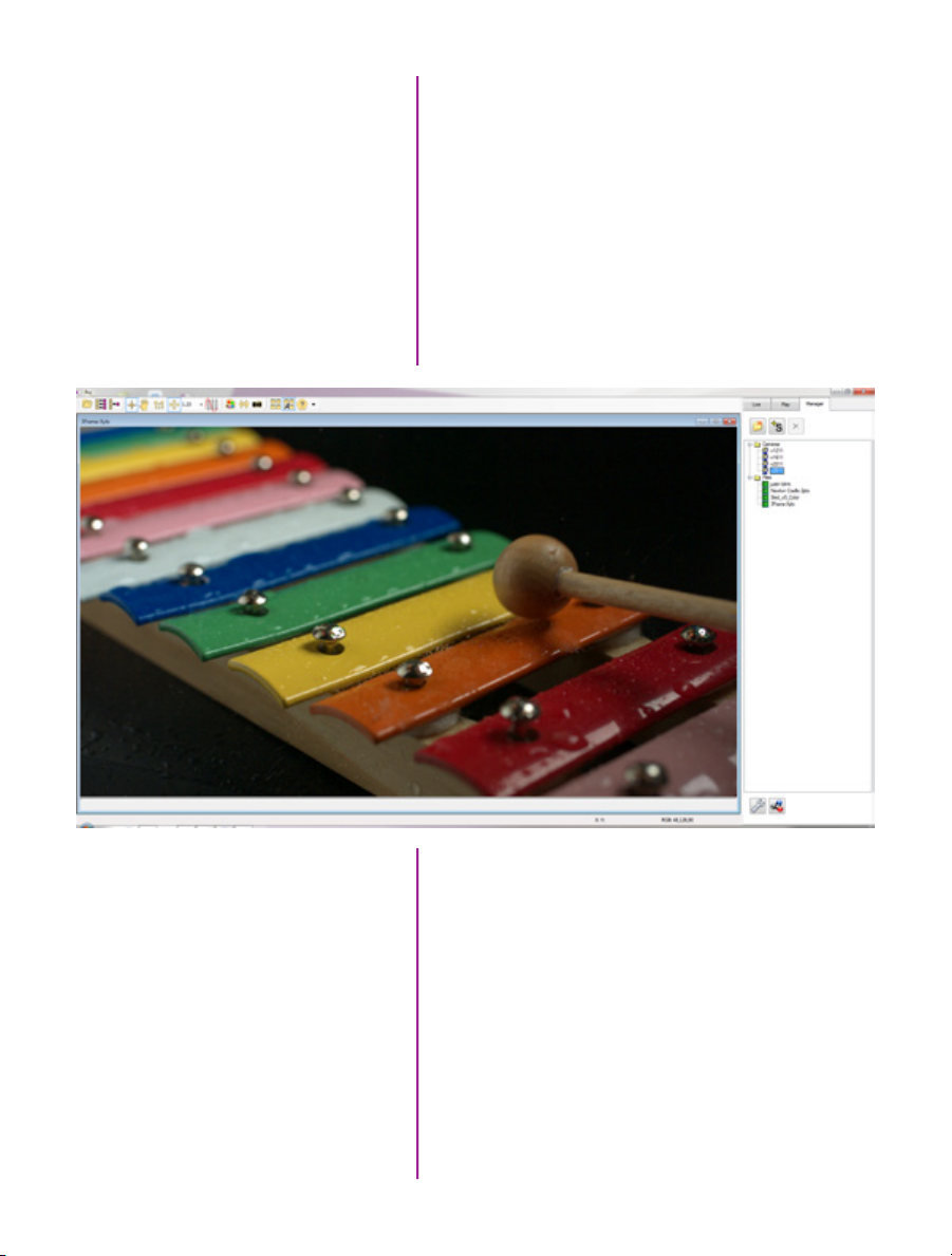
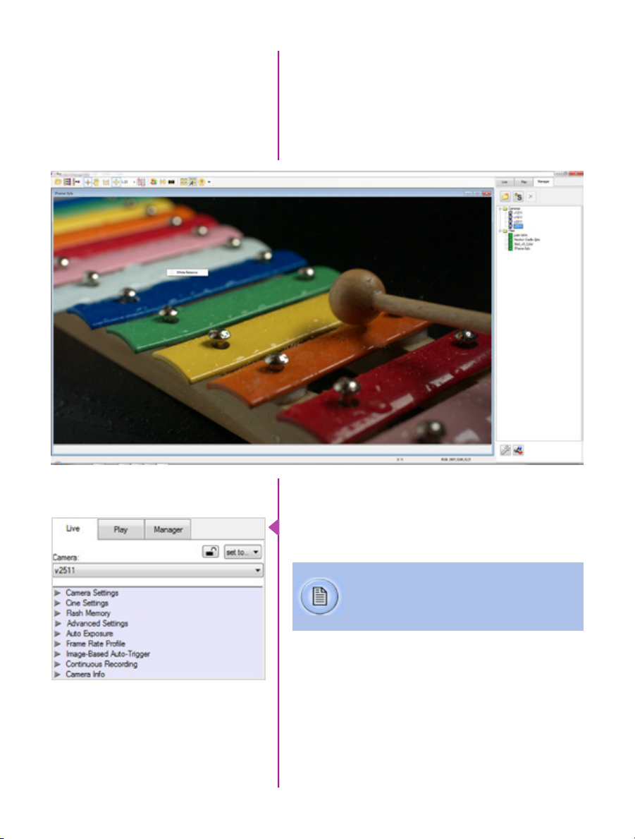
Control Tabs
The main window of PCC is divided into three tabs: Live,
Play and Manager.
When first started, the ‘Manager’ tab is selected. It is in
this tab connected cameras are displayed, selected for
use, and renamed. It is also used to manage saved Cine
files.
To rename, highlight then click the name of a camera.
This can be useful when working with multiple cameras.
All camera control and setting of shooting parameters
(frame rate, shutter, etc.) is performed in the ‘Live’ tab.
The ‘Play’ tab is used to review, edit, and save Cine files,
(either from the camera or from files on the local hard
drive).
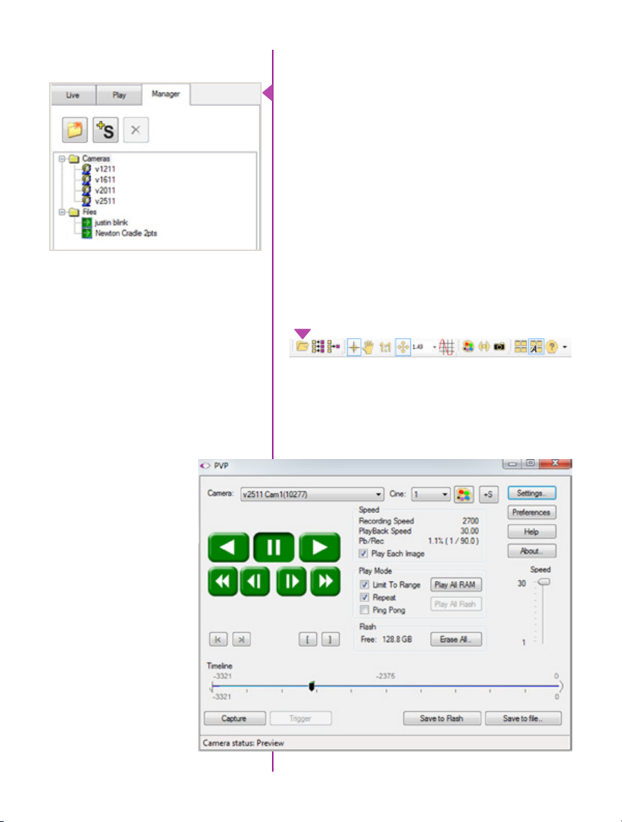
PVP (Phantom Video Player)
Application Overview
18
Phantom Ultrahigh-speed Camera Manual
PVP can be launched directly from the desktop, or
by clicking the ‘Video Out’ toolbar button in PCC. PVP
controls only the camera’s HD-SDI outputs as connected
to a compatible SDI monitor.
Page 25
PVP, provides the ability to view, capture, review, edit, and/
or save a Cine recorded into the camera’s RAM to a hard
drive, or installed Phantom CineMag IV. PVP is extremely
effective when used with the high-resolution cameras
since most computers are not powerful enough to view
the live or captured raw files smoothly.
The camera’s video mode and display settings are also
pcc software
set through PVP. Video systems will vary based on the
country you are in, what kind of video monitor used, and
the required display resolution. All available video setting
for the connected camera can be found in the ‘Settings’
menu of PVP.
Camera Control via PCC
PCC provides the ability to select various units for specific
camera parameters by clicking the ‘Preference’ button at
the bottom Manager tab.
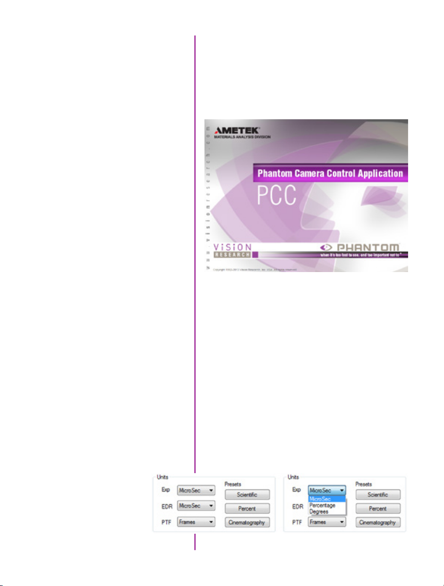
Units can be set to commonly used values (‘Presets’) or
they can be customized using the pull-down selection
lists. First time users should use one of the three ‘Presets’.
19
Chapter 3: Phantom Software
Page 26
The ‘Exp’ unit is probably the most important unit to be
set. It specifies what unit to use when setting the exposure
time. You probably will want this set to micro-seconds.
The other unit to set is PTF (Post Trigger Frames) covered
later in this section. All Phantom Ultrahigh-speed cameras
support EDR (Extreme Dynamic Range) exposure.
Selecting a Camera
Double-click the camera(s) to be controlled listed in the
‘Manager’ tab, or select the camera(s) from the ‘Camera’
pull-down list in the ‘Live’ tab.
Image Processing
20
Phantom Ultrahigh-speed Camera Manual
Once a camera is selected a ‘Preview’ panel will display
to the left of the control tabs showing the current image
being captured by the camera. This image may differ
slightly to that of the image being output over the
camera’s two HD-SDI ports due to display differences
in the video monitor and computer screens.
Page 27
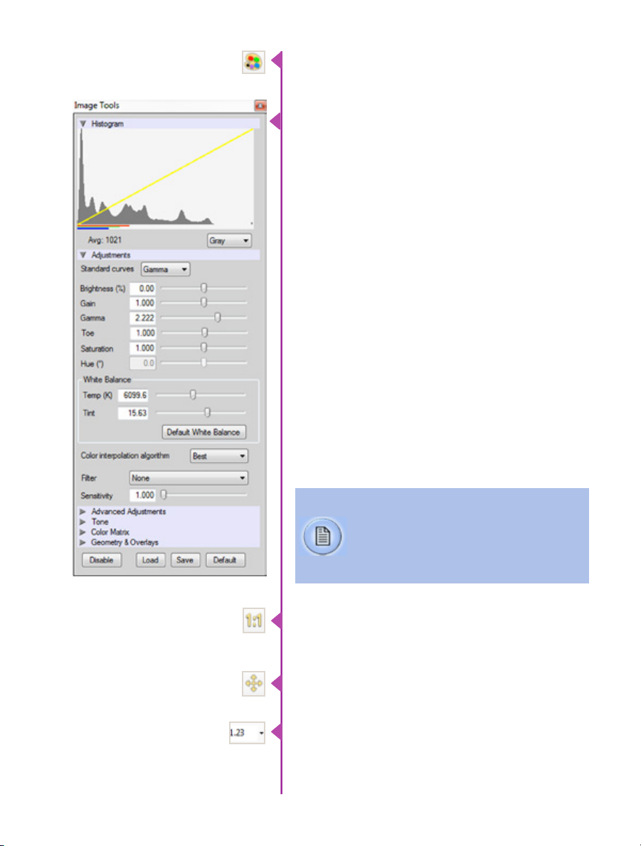
You can adjust the display options by clicking on the
‘Image Tools’ toolbar button.
The ‘Image Tools’ window is used to view a ‘Histogram’
and change settings that affect the computer display and
the video output of the camera.
Some of the variables include; brightness, gain, gamma,
saturation, hue, white balance adjustments (Temp (K) and
Tint), individual red, green and blue pedestal, gain and
gamma values, tone control, and more.
When Log mode is selected, most of these variables are
locked and can not be adjusted.
At the bottom of the window is a ‘Default’ button that
restores all parameters except white balance, tone, and
color matrix to their default values.
The ‘Default White Balance’ button restores white balance
to the default (which under the most typical lighting will
produce a green image).
The Tone ‘Reset’ button restores the image tone to the
default values, and the Color Matrix ‘Restore’ button return
the color matrix values to their default values.
Changes made only affect the meta data of the
Cine file, not the raw data. If you are recording
the camera’s video output it is important that
these be set to values that produce the image
you wish to record.
The ‘Zoom Actual Size’ toolbar button resizes the images
being displayed in the Preview/Playback panel to their
actual size.
The ‘Zoom Fit’ toolbar button resizes the images to fit
panel.
Images can also be zoomed to a specific magnification
ratio by selecting a number from the pull-down list to right
of the Zoom Fit button.
Chapter 3: Phantom Software
21
Page 28
Automatic White Balance
Once a camera is selected a ‘Preview’ panel will display
to the left of the control tabs showing the current image
being captured by the camera. This image may differ
slightly to that of the image being output over the
camera’s two HD-SDI ports due to display differences
in the video monitor and computer screens.
Capture Settings
22
Phantom Ultrahigh-speed Camera Manual
Just below the ‘Camera’ selector in the ‘Live’ tab are a
series of expandable headers, which contain groups of
related camera settings.
This manual will cover the most commonly
used settings, see the ‘Pcc Help’ file for details
of other settings.
Page 29

Camera Settings
& Cine Settings
Set Time: Synchronizes the time stamps embedded
in the recorded image data to the computer’s clock or
supplied IRIG-B clock.
Camera Settings are used
to set and recall the overall
camera system parameters.
Cine Settings are used to set
the capture parameters.
Bit Depth: The Phantom v1212, v1612, v2012, and
v2512 camera operate in 12-bit mode only.
Partitions: Select the number of desired partitions (evenly
divided memory segments) from the ‘Partitions’ pull-down
menu. For basic camera setups, this should be set to one.
Lens Control: Will be available for Canon EF lenses only,
for control of aperture and focus.
Backup & Restore: Allows for user settings to be saved
and recalled from the camera’s memory.
Resolution: Set the number of pixels used to capture an
image. For example, if 1280 x 800 (width x height) is set,
the full sensor space is available. Smaller resolutions allow
higher recording speeds. Cropped resolutions are set
using the ‘Crop and Resample’ menu in Image Tools.
Sample Rate: Set the acquisition frame rate in framesper-second (FPS).
Exposure Time (shutter): Set the exposure time in
microseconds, percentage, or degrees (this depends on
how the PCC preferences are set).
EDR (Extreme Dynamic Range): Set a unique
exposure time (defined in microseconds or a percentage
of the defined ‘Exposure Time’) to pixels that may become
saturated, (over exposed).
Exposure index: This is a reference display of the EI
value in relation to the Image settings.
CSR (Current Session Reference): Closes the camera’s
internal shutter and resets the black point of every pixel
for optimal image quality.
Image Range and Trigger Position: The slider
represents the memory buffer, with the ‘Duration’
indicated in seconds and the total number of frames
available.
Chapter 3: Phantom Software
23
Page 30

The trigger position is indicated in the ‘Last’ pull-down
menu or as the ‘T’ slider along the timeline. The trigger
position is the point at which the camera stops continually
recording when a trigger signal is detected.
Key Advanced Settings
The first of these key features is the option to enable
the ‘Start/End of recording actions’ to be performed automatically at the beginning or end of a shot. The
most common ones are:
• ‘Auto save to CineMag/Built-in Flash’ this feature
saves a user-specified portion of a clip to the
Phantom CineMag immediately after recording.
• ‘Auto play Video Out’ begins playback after
recording. The range marked under ‘Auto play Video
Out’ affects both playback and saving to the
Phantom CineMag.
• ‘Restart Recording,’ when enabled, automatically
restarts the recording process after the ‘Auto’
actions have been performed.
When ‘Restart Recording’ is enabled PCC
does not provide any user confirmation
before the clip is erased from RAM and
starts recording again. This feature should
be used with care!
‘External Sync’ instructs the camera to utilize one of the
following three frame sync clock sources:
• Internal - instructs the camera to utilize its’ internal
crystal oscillator to drive the camera’s frame rate.
• External - should be selected when an externally
supplied frame sync clock pulse is supplied to drive
the frame rate. This can be used to synchronize two
cameras together via F-Sync.
• IRIG - should be selected when an IRIG-B signal is
supplied to drive the camera’s frame rate.
• LockToVideo - Frame rate is driven by the camera’s
current video rate. FPS will jump to the closest
multiple of the current video rate (23.98, 24, 25,
29.97 or 30).
24
Phantom Ultrahigh-speed Camera Manual
Page 31

Flash Memory
Specifies the camera’s operation mode in relation to
CineMag recording: Loop (record to RAM first) or R/S
(bypass RAM and record directly to CineMag).
It also displays the amount of ‘Free’ space and size
(in Gigabytes) of the Phantom CineMag.
Recording a Cine
Triggering the Camera
In ‘Loop’ mode to begin recording to the camera’s RAM
click the red ‘Capture’ button.
The red ‘Capture’ button changes to ‘Abort Recording’
and the green ‘Trigger’ button is enabled when the
camera is recording. The Abort Recording button instructs
the camera to stop recording, leaving the camera’s
RAM empty.
Selecting the ‘Trigger’ button instructs the camera to
immediately stop recording when the ‘Trigger Position’ is
set to zero. If a value greater than zero is set, the camera
will continue to record ‘post-trigger’ frames until the
userspecified value is met.
If a clip exists in the camera’s memory, you will
be asked if you are sure you wish to delete it
before continuing. If yes, click ‘Delete cine(s)
and start new recording’.
Set R/S (Run/Stop) mode by selecting the ‘Direct
Recording to CineMag’ box in the Flash Memory section.
Start recording by clicking the red ‘Record’ button. Once
the camera is recording directly to the Phantom CineMag
the ‘Record’ button changes to a ‘Stop Recording’ button.
Using the camera’s ‘Trigger’ button, or an
external trigger signal provides a more accurate
trigger to the camera.
Chapter 3: Phantom Software
25
Page 32
Reviewing a Cine
Once the camera has completed recording a Cine in
the camera’s RAM or CineMag it can be reviewed by
selecting it from the ‘Cine’ pull-down selection list in the
PCC ‘Play’ tab.
A previously saved Cine stored on the computer’s
hard drive can be opened using the ‘Open File’
toolbar button (also places the file under the
‘Cines’ group folder in the Manager tab).
The viewing option can be changed via the ‘Play Speed
& Options’ and the Cines’ metadata can be viewed in the
‘Frame Info’ and ‘Cine Info’ sections.
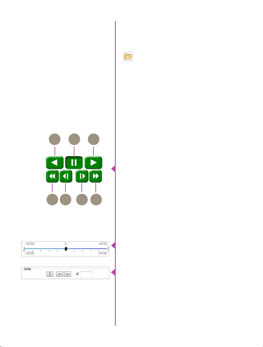
Use the ‘Video Control’ buttons to review the cine.
Rewind
A
A
DBE
C
F G
Performing a Quick Search
Through a Cine
Pause
B
Play
C
Fast Rewind
D
Rewind 1-Frame
E
Advance 1-Frame
F
Fast Forward
G
Quickly search through cine files to find the points of
interest:
‘Scroll’ (scrub) through the clip using the ‘Image Location’
slider or click anywhere on the timeline to jump to points
in the cine quickly.
‘Jump’ to the trigger frame by clicking on the ‘T’ button,
or jump to specific frames by entering the frame number
into the jump ‘#’ data entry field, then hit the enter key.
26
Phantom Ultrahigh-speed Camera Manual
Page 33
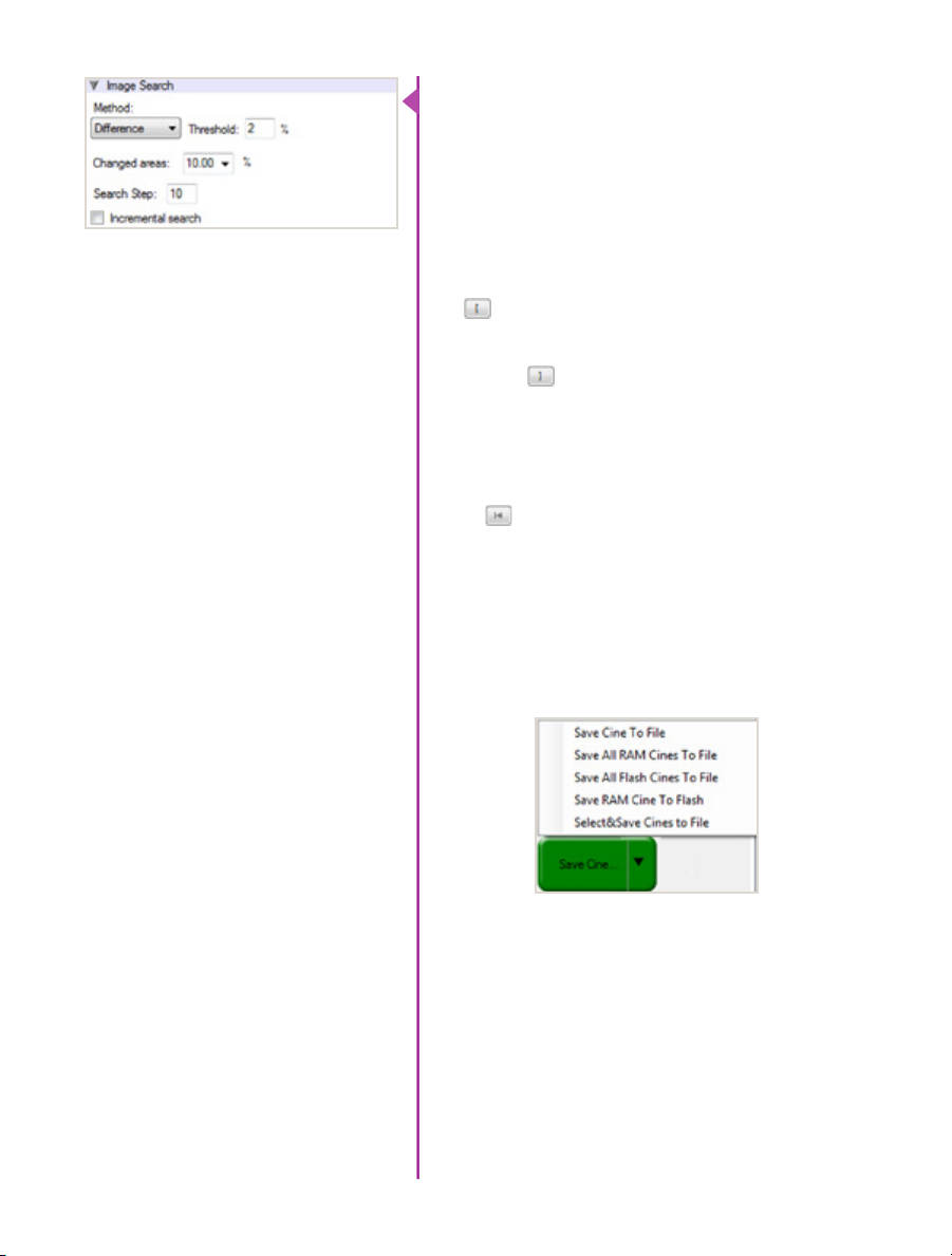
‘Image Search’. The goal is to search or find an image
change in the recording, based on the difference between
image content. Right-Click on the ‘Play’ button to begin
the image search. Besides image content changes, Image
Search can also look for images that are tagged as ‘Event’
images.
Editing a Cine
Saving a Cine
Using the following ‘Video Control’ buttons locate the
first image of the cine to be saved and click the ‘MarkIn’ button.
Locate the last image of the cine to be saved and click the
‘Mark-Out’ button.
Click ‘Play, Speed, & Option’ and enable (check) ‘Limit to
Range’.
Under the ‘Video Control’ buttons click the ‘Jump to
Start’ button, then review the edited cine.
Click the ‘Save Cine...’ button to save the edited cine to
the computer’s hard drive.
If you wish to save the clip to an attached Phantom
CineMag, click the down-arrow to the right of the ‘Save
Cine...’ button and select ‘Save RAM Cine to Flash’.
For further instructions on working with CineMags, please
see Chapter 7: Phantom CineMag & CineStation IV.
Chapter 3: Phantom Software
27
Page 34
Using PVP
(Phantom Video Player)
PVP (Phantom Video Player) is a streamlined application
used to control the video playback of the camera, and can
be used to quickly capture, review, edit and save to or
from the CineMag.
PVP can be opened directly from the desktop or by
clicking the ‘Video Out’ toolbar button in the PCC software.
PVP Settings
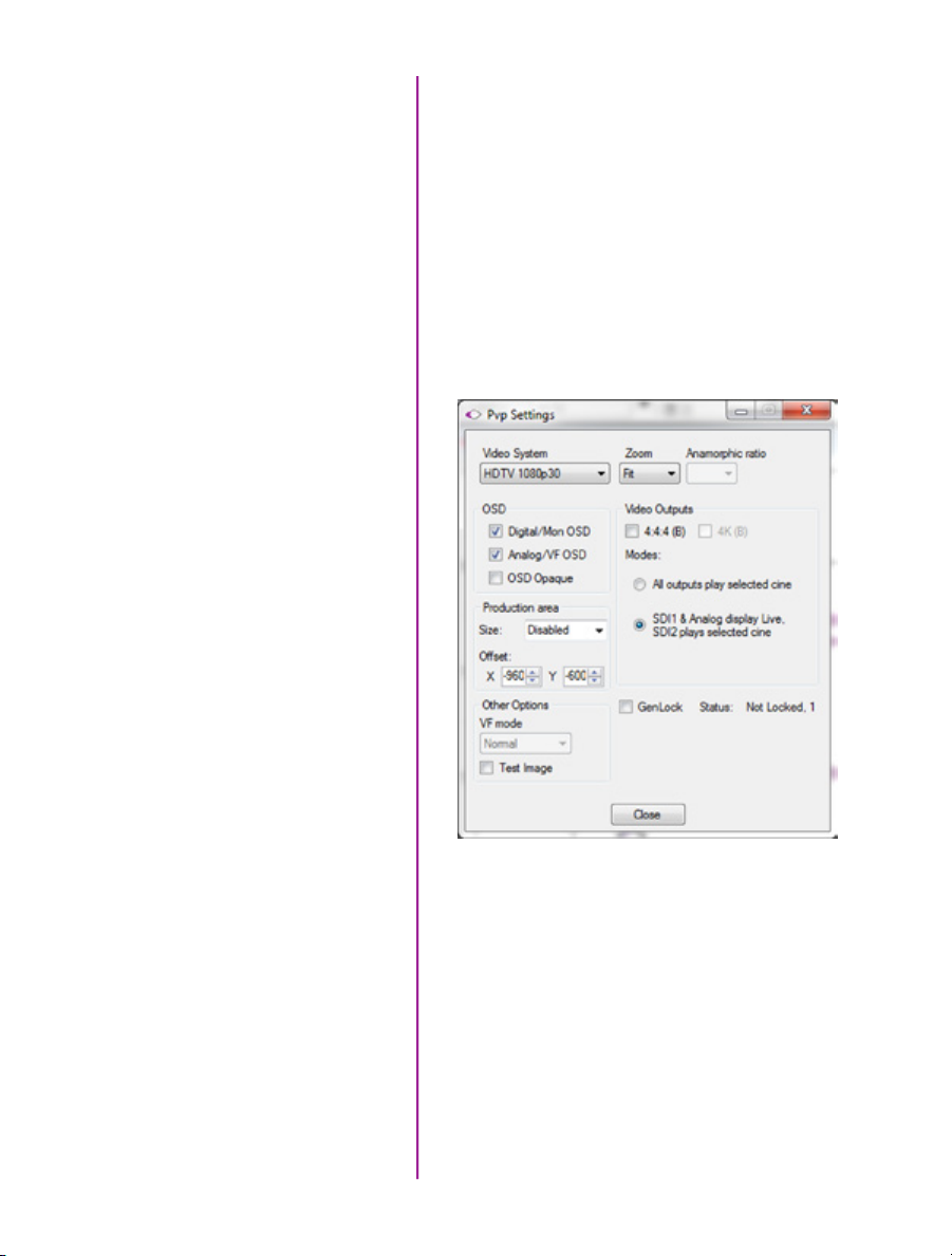
Video output parameters are set by opening the ‘Pvp
Settings’ windows. This includes control for the video
system, 4K video and on-screen display parameters
including production area rectangles.
pvp software
Image Tools
Click on the palette from the main PVP window to activate
the ‘Image Tools’ menu. It is basically the same as the
equivalent menu in PCC. It can be used to adjust image
processing parameters including; brightness, gain,
gamma, toe, saturation, white balance and more.
28
Phantom Ultrahigh-speed Camera Manual
Any image tools adjustments will also apply to the PCC
live image and the metadata in saved Cine Raw files.
Page 35

The Main PVP Window
Basic capture and playback are performed from the main
‘PVP’ window. The ‘Capture’ button starts recording to
RAM when the camera is in ‘Loop’ mode. Press ‘Trigger’
to stop recording.
Switch to the desired clip to view by selecting it in the
‘Cine:’ pull-down menu. Clips from the Phantom CineMag
are preceded by the letter ‘F’. To return to the live output,
select ‘Live.’
Scroll through a Cine by dragging the play head back
and forth on the timeline. Use the playback controls
to play forward and in reverse. Use the speed slider
to change the playback speed.
Use the ‘[‘ and ‘]’ buttons to mark in and out points.
After trimming a clip, press the ‘Save to Flash’ button
to save it to the Phantom CineMag, or ‘Save to File…’
to download it to the computer.
It is also possible to erase the entire contents of a
CineMag by clicking the ‘Erase All…’ button.
29
Chapter 3: Phantom Software
Page 36

30
Phantom Ultrahigh-speed Camera Manual
Page 37
Download &
4
Introduction
PCC Software Solutions
Converting Cine Files
Image Processing
The images recorded on the camera’s RAM or Phantom
CineMag are stored in a Vision Research proprietary RAW
(uncompressed) file structure called a ‘Cine’ file.
These Cine files can be converted to industry standard
formats (ProRes, H264, DPX, DNG, TIFF, JPEG, and more)
with PCC software provided by Vision Research. Phantom
PCC and PVP software are only compatible with Windows
operating systems, however there are third party solutions
available for working with Phantom cameras in Mac OSX.
Windows-based PCC software provides the ability to
convert cine files into a number of other formats.
Single cine files can be converted by selecting the desired
format from the ‘Save as Type’ selection list in the ‘Save
Cine’ dialogue window.
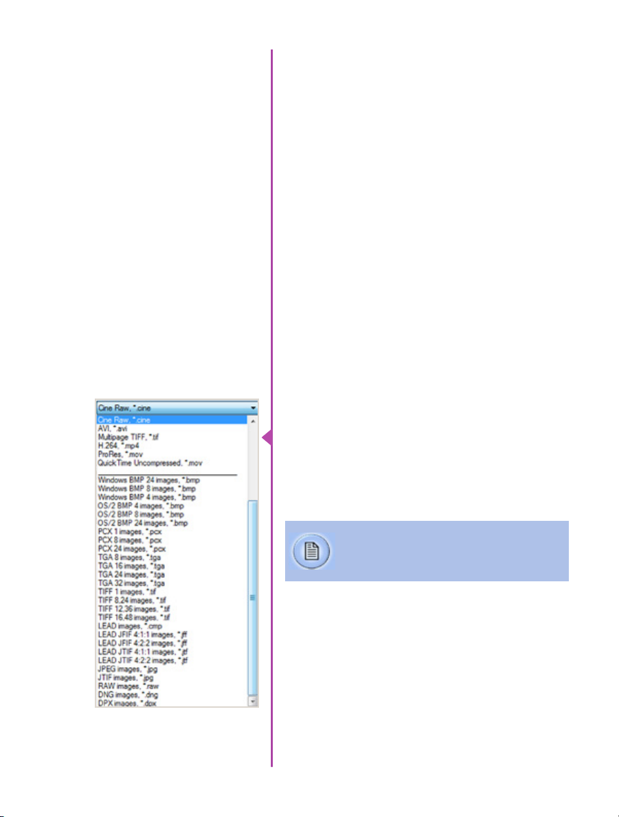
The file formats above the separator line in the ‘Save as
Type’ selection list are ‘movie-like’ formats (meaning the
entire clip will be saved as a single file) while the formats
below the line are image formats (meaning each frame of
cine will be saved as a sequence of images).
Re-saving a clip in the ‘Cine RAW’ format can
be useful for creating sub-clips with no loss in
image quality or metadata.
To convert a cine to a ‘movie-like’ format select the
desired format from the list, navigate to the destination
folder, assign a file name to the clip and save.
Some valuable parameters can be found in the ‘advanced
settings’ window, such as the particular codec. In the case
of ProRes, the default is 4:2:2 HQ, however other options
are available.
Chapter 4: Download & Image Processing
31
Page 38

Other formats, like .avi and .mp4 allow the compression
ratio to be entered. The lowest compression is the default.
To convert a cine clip into a sequence of images (frames)
you must add one of the following annotations to the
end of the file name: ‘!n’ or ‘+n (where n is the number
between 1 to 8). This will assign the sequential frame
numbers to the file name for each frame being created.
Example: image_!5.tif
The ‘!’ annotator instructs the software to append the
cine’s image number (relative to the trigger point) to the
file name. If the first frame in the clip is - 100, then the
first converted frame will have the name: image_-00100.
tif.
The ‘+’ annotator will add frame numbers starting from 1.
Example: image_+5.tif
This will cause the first converted frame to have the name:
image_00001.tif
Ensure all image adjustments have been applied prior to initiating the conversion process.
All metadata (gain, gamma, saturation, etc.) will
be embedded into the converted images.
Batch Convert
32
Phantom Ultrahigh-speed Camera Manual
The ‘Batch Convert Files’ toolbar button can be used to
convert a single, or multiple saved cine files into any one
of the supported file formats.
Use the shift and/or control keys, to select the cine files
you wish to convert in the ‘Open Cine’ dialogue window,
then click the ‘Open’ button.
Navigate to the destination folder, in the ‘Multifile Convert
Destination’ dialogue window, and select the file format.
Page 39
The ‘File Name’ will depend on the type of file format you
are converting to.
If you are converting the cine file into a ‘movie-like’
formats leave the file name as ‘All selected file.’ The
software automatically assigns the original file name
to the converted file and appends the appropriate file
extension.
However, if you are converting the file into a sequence
of images, you need to enter the annotation only detailed
in the ‘Convert a Cine’ topic earlier in this chapter.
Example: +4
The software automatically creates a separate folder for
each of the files being converted, assigns the original file
name, and appends the appropriate image number and
file extension to each image.
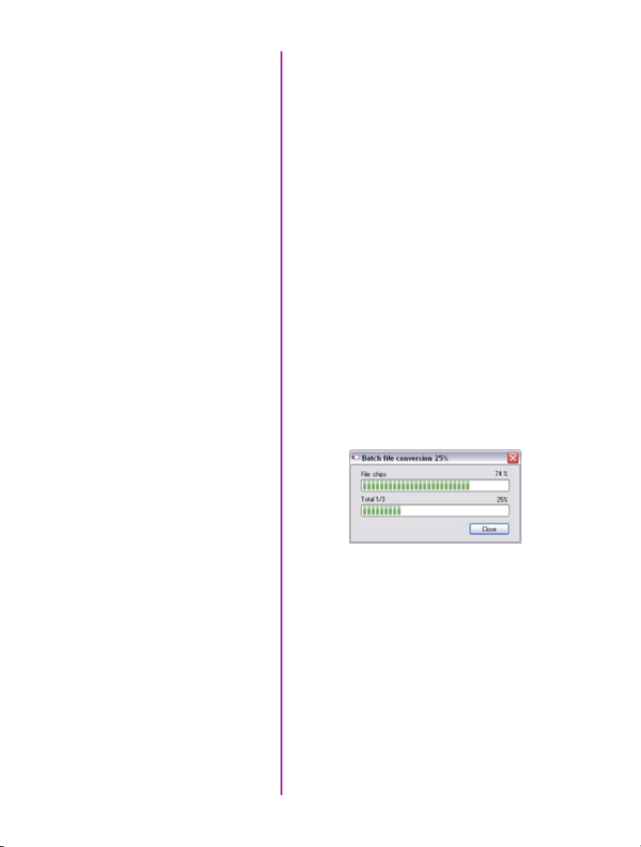
Once the ‘Convert’ button is clicked a progress window
appears. Each converted cine will be placed in its own
folder named after the original cine file.
33
Chapter 4: Download & Image Processing
Page 40
For details on how to use the various PCC measurement tools can be found in the Phantom (PCC) Camera Control
34
Phantom Ultrahigh-speed Camera Manual
Application Help File > Step-by-Step Procedures > Play Panel Procedures > Measurements.
Page 41

5
Measurements
Introduction
High-speed photography is as much of an engineering tool
as an oscilloscope, spectrum analyzer, or logic analyzer.
The photographic technique enables us to visualize and
analyze motion, especially motion that is too fast for the
human eye or conventional cameras to perceive.
For decades, Phantom Cine (high-speed digital video)
files have been used to measure moving objects by
the defense, scientific and research, and industrial
communities to extract and quantify motion from a file.
As high speed digital cameras continue to make
advancement in recording speeds, sensitivity and
resolutions so must the motion analysis software used to
extract the data they record. Data that allows the defense
community to examine the speed, angle and angular
speed a shock wave from an explosive device.
Information automotive engineers require to evaluate
the safety and effectiveness of an airbag design by
determining the time, speed, and angle it takes the airbag
to deploy fully. Studies by the scientific and research
community analyzing human locomotion by measuring
the angle a knee joint bends and the compression the
knee joint endures while running, or the speed of a
lightning bolt. Not to mention manufacturers needing to
measure the angular speed (Revolutions Per Minute) a
new hard drive motor can spin without causing damage
to the disk, or being able to measure the effect the angle
of impact a golf club will have on the rotational speed of
a golf ball.
The ability to analyze all of this data quickly and accurately inherently decreases product development time,
and more importantly reduces research and development
expenditures. Of course extracting this information from a
digital high speed video is only as good as the tools used
to accomplish it.
Chapter 5: Measurements
35
Page 42

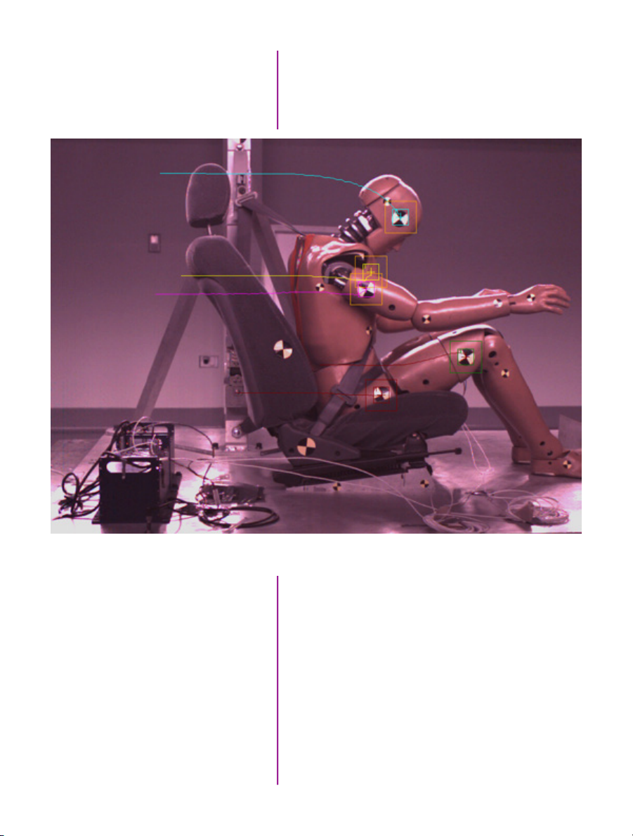
PCC Multi-Layer Graphical User Interface automatically tracks golf club head to calculate swing speed, path, and acceleration.
Using 2-D motion analysis tools, such as Vision Research
PCC (Phantom Camera Control) software calculates this
valuable data. With today’s software, the end-user can
perform timing, position, distance, velocity, angle and
angular speed measurements, and track multiple points
or objects to compute and graph their XY-coordinates,
speed, or acceleration. PCC, for example, provides several
edge detection algorithms and image processing tools
to improve the measurement process. The measurement
technology provides a motion analysis system that
harmonizes measured data with images. In this chapter,
we will review the various PCC measurement capabilities.
Units of Measurement
36
Phantom Ultrahigh-speed Camera Manual
Units of Measurement specify the computing and
reporting unit for distance, speed, acceleration, angle,
and angular speed measurements.
Page 43

Establishing a measurement scale is required to set a
specified number of pixels in the image equal to a scale
unit size, such as millimeters, meter, inches, feet, or pixels.
To define a measurement scale, the analyst needs to
select two points on the image with a known scale, then
specify that scale size. Once created, all measurements
are computed and displayed using the scale unit. If no
measurement scale exists, the default scale will be
1 pixel = 1 pixel.
Timing
Coordinate
Distance, Angle, Speed
To perform timing measurements accurately, a time stamp
(date and time) is embedded into every frame captured.
The PCC software function, for example, calculates the
time difference between two event frames (start / end of
an event) or from the captured image being displayed to
the trigger (t0) frame automatically.
Coordinate measurements are calculated from an Origin
point pixel, by default the top-left corner of the image;
however, the Origin can be changed when performing
measurements. Each coordinate consists of two numbers
(x1, y1) indicating the position of a pixel in the image on
the two-dimensional plane from the Origin point.
Using ‘Distance and Angle and Speed’ instant
measurement tools makes analyzing launch speed,
angle, and angular speed or the revolutions of a rotating
object extremely simplistic.
They allow engineers’ developing large caliber weaponry
to analyze the effect the design of the shell has on the
projectile trajectory based on launch speed and angle to
determine the optimal performance, or manufacturers of
scientific equipment like anemometers to determine the
best size and type motor to enhance their product by
performing angular speed (rotational measurements) on
the motors used to generate an electric current as they
rotate.
37
Chapter 5: Measurements
Page 44

PCC measures the distance from the Origin point to a
selected point, and the angle made by the Origin and Ox
axis of the selected point using the Distance and Angle
and Speed: Origin + 1 Point instant measurement tool.
Given the coordinates of two points on the image plane,
the distance (d) between the points is calculated using the
following formula: d=√((x2-x1)2) + (y2-y1)2).
If the Origin and the selected point are on the same image, PCC will calculate distance and angle only; however,
if the Origin and the selected point are on different frames,
the software also calculates speed and angular speed.
Speed (s) is calculated using the formula: s=d/dt , where
d = measured distance, and dt = [time of the point frame]
– [time of the origin frame] if point and origin are on
different frames.
38
Phantom Ultrahigh-speed Camera Manual
Angular speed is calculated using the formula: as=a/dt,
where a = measured angle, and dt = [time of the point
frame] – [time of the origin frame] if point and origin are
on different frames.
The ‘Angle and Angular Speed: 3 Points’ instant
measurement tool from PCC calculates the angle made
by three points (two lines with a common reference point)
while the Angle and Angular Speed: 4 Points calculates
the angle formed by four points [Pt.1 Ref.1 and Ref.2
Pt.2]; two lines without a common reference point.
Page 45

If all the points are in the same image when performing
three or four-point measurements, the software only
calculates the angle. In order to compute angular speed
the first point and the reference point must be on the
same image while the second point (three-points measurements) or reference point 2 and point 2 (four-point
measurements) must be on different images.
Angular speed is calculated using the formula: as=a/dt,
where a = measured angle, dt = [time of the last point
frame] – [time of the first point frame] if first and last
points are on different frames.
PCC calculates speed (mph) and angular speed (rpm) of the fan motor using Distance, and Angle, and Speed:
Origin + 1 Point measurement tool
These measurement tools are exceptional when analyzing
a rotating object.
The ability to measure an object, like a projectile rotating
in mid-air, to determine its angular speed can be applied
to other sciences, for example, the way 2 x 4 board
could tumble in hurricane-force winds can be applied by
manufacturers who develop unbreakable glass windows,
or engineers developing stabilizers for aircraft.
Chapter 5: Measurements
39
Page 46

Collect Point (Tracking)
PCC also provides a Collect Point (tracking) tool to compute the position, speed, acceleration, and / or generate
motion graphs of a point (or object) or multiple points (up
to 99), with respect to the image plane, over time. The
analyst can use one of two methods to track 2D motion
(Automatic or Manual).
Example of three points being tracked. The graph plots and displays, by default, the x-axis coordinate of all points / targets from the Origin point.
40
Phantom Ultrahigh-speed Camera Manual
With Automatic Tracking, the analyst needs to define a
rectangle (width and height in pixels) around a template
image region (the point being tracked). The analyst
defines a second rectangle that the tracking algorithm
should search in (how large of an area to search) for the
previously tracked point. A value equal to the track point
indicates that the tracking algorithm should search in a
region as large as the initial region size.
Page 47

Data Acquisition
Larger values will result in greater search areas,
which will take a longer time to search. Typically this
parameter is set two to three times the size of the initial
image template (defined in pixels). When initiated, the
software will automatically find and track the template
region as it progresses through each frame.
Manual Tracking requires the analyst to select every point
being tracked for each frame. With either method all
tracked points are logged to a measurement file that can
be used to generate a coordinate, speed, or acceleration
spreadsheet easing report generation.
To investigate the effect environmental conditions may
have on the recorded data, a National Instruments™
USB- or M- Series Data Acquisition (DAQ) module
can also be used to acquire data from a wide range
of sensors, and synchronize it with slow-motion video
images recorded on a Phantom camera, using Phantom
Camera Control (PCC) software.
Chapter 5: Measurements
41
Page 48
SDK (System Developer Kit)
Phantom camera control, and Cine playback, analysis and
measurements can be customized to meet specific test
protocols using the Phantom System Developer Kit (SDK)
for LabVIEW (Laboratory Virtual Instrument Engineering
Workbench) or MATLAB (matrix laboratory) drivers.
The LabVIEW SDK contains visual instrument (VI) files
needed to call Phantom SDK functions from LabVIEW,
various utilities, and demo applications. This SDK uses
the LabVIEW interface to shared libraries to call functions
from Phantom libraries.
The MATLAB SDK contains header files needed to call
Phantom SDK functions from MATLAB, function wrappers,
a simple object-oriented layer and demo scripts. This
SDK uses the MATLAB interface to shared libraries to call
functions from Phantom libraries.
SDKs allow, for example, automotive manufacturers to
create command line scripts to control a Phantom camera
directly from a computer or run in a Graphical User
Interface specifically designed to perform or analyze
airbag tests with having to use PCC. Anyone who wishes
to have more control over their Phantom camera or the
Cine files record would benefit using one of these
Phantom System Developer Kits.
42
Phantom Ultrahigh-speed Camera Manual
Page 49

Conclusion
Digital high speed video has been and continues to be
a useful test and measurement tool.
Along with PCC software the need to use calculators
or slide rules to perform complicated mathematical
calculations to compute distance, speed, angle, angular
speed, or acceleration measurements of single or multiple
points from 2D images has been eliminated.
The ability to perform these calculations with just a few
clicks of a mouse button allows engineers, science and
researchers, and developers will significantly reduce
research and development time thereby increasing
productivity.
These tools provide them with the ability to conduct
even more precise and accurate analyses of ballistics,
explosions, weapon’s development, trajectory,
biomechanics, sport performance, flow analysis, crash,
combustion, and stress studies, just to mention a few.
43
Chapter 5: Measurements
Page 50
A B C D E
F G H I
Camera State
A
Internal Memory
B
live preview screen
44
Phantom Ultrahigh-speed Camera Manual
Number of Frames Available
C
Recording Duration
D
Time Stamp
E
Frame Rate
F
Serial Number / Name
G
Exposure Time
H
Resolution
I
To view the ‘On-Screen Display’ (OSD) power
the camera and connect a video monitor.
Page 51

6
On-Screen Displays
Camera State
Internal Memory
Number of Frames Available
Recording Duration
Time Stamp
Frame Rate
Serial Number / Name
Exposure Time
Resolution
The symbol and color will change based on the state
A
of the camera.
Live Pre: camera is in LOOP mode but is not
recording to internal memory. Displays a ‘Live’ image
on the video monitor.
Waiting for Trigger: camera is recording to internal
memory (RAM), and awaiting a trigger signal. Displays
a ‘Live’ image on the video monitor.
Triggered: camera has been triggered, and is filling
internal memory (‘Post-Trigger’ frames). Displays a
‘Live’ image on the video monitor.
Cine Stored: recording has ended, and a cine is
stored in internal memory. Displays a ‘Live’ image on
the video monitor.
Playback: camera is in PLAYBACK mode a cine can
be selected for playback.
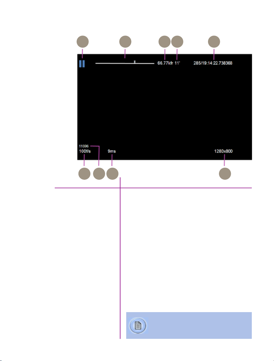
This ‘time line’ represents all frames available in
B
the camera’s internal memory (RAM buffer / circular
buffer). The ‘T’ symbol above the time line represents
the user-defined trigger point
Indicates the exact number of recordable frames
C
available in the camera’s internal memory.
Indicates the total length of recording time
D
(in minutes and/or seconds).
Indicates the day of the year/hour:minute:second:
E
microsecond.
F
Indicates the user-defined frame rate.
Indicates the camera serial number or user-defined
G
camera name.
Indicates the user-defined Exposure Time
G
(in milliseconds or microseconds).
Indicates the user-defined resolution (width x height),
I
in pixels.
Chapter 6: On-Screen Displays
45
Page 52

How to Set
the Parameters
camera menu
1. From any of the ‘Live’ screens; rotate the Menu
knob to display the ‘Camera’ menu
2. Rotate the knob to the desired camera parameter,
then press the knob to select
3. Rotate the knob, in either direction, to change the
selected parameter, then press knob to confirm
Frame burst
46
Phantom Ultrahigh-speed Camera Manual
Speed
Shutter
Defines the ‘Speed’ (Frame Rate / Sample Rate) that the
camera will capture at. The available speeds will change
according to the ‘Resolution’ selected. Smaller resolutions
allow higher speeds.
The Resolution parameter should be set before
setting the Speed.
Defines the amount of time the sensor is exposed to
light (in degrees of shutter angle and μs of exposure time).
A small shutter angle or short exposure time reduces the
chance of motion blur.
Sets the number of frames in a burst, (‘off’ disables Burst
Mode).
Page 53

Period
Sets the interval between frames in a burst (defined in
microseconds).
Trigger
Res
Capture
This ‘time line’ represents all frames available in the
camera’s internal memory (RAM buffer / circular buffer).
The ‘T’ symbol above the time line sets the trigger point.
Frames before the ‘T’ are ‘Pre-trigger’ frames, while
frames after the ‘T’ are ‘Post-trigger’ frames.
Resolution is the number of pixels used to capture an
image. For example, if 1280x800 (width x height) is set,
the full sensor space is available. This is called
‘Full Frame’.
Smaller resolutions (320 x 240) for example allow higher
recording speeds.
The image aspect ratio will be displayed with
the defined Resolution setting.
This field selects whether the camera is to run in Loop or
Run/Stop (R/S) mode.
In Loop mode, a trigger signal starts the recording and
stops after all ‘Post-trigger’ frames are recorded. This is
the default setting. Any cine can be played over HD-SDI,
or saved to an attached computer, or Phantom CineMag IV
(if available).
Auto bref
In Run/Stop mode images are recorded directly into an
attached Phantom CineMag IV.
In R/S mode no ‘Pre-Trigger’ frames are
saved, and the user must start and stop each
recording.
When set to ‘on’ a black reference operation will be
performed when the camera is placed into the capture or
‘waiting for trigger’ mode with the results being saved
with the cine.
47
Chapter 6: On-Screen Displays
Page 54

For cameras with an attached Phantom CineMag IV
operating in R/S mode, the recording into the Phantom
CineMag IV is delayed until the black reference operation
has completed. All frames saved to the Phantom
CineMag IV will be corrected with the obtained CSR
(Current Session Reference).
The camera will show the PA (Production Area) specified
PA
placing a red rectangle over the image. The production
area is an overlay and is not recorded in the RAW data.
PAO
Zoom
Color Bars
The PAO (Production Area Offset) parameters are used
to move the user-defined PA (Production Area) displayed
on the attached monitor. By default, the Production
Area Offset will set to 0,0. These settings instruct the
Production Area to be displayed in the center of the
image display area.
The first POA variable offsets, or moves, the Production
Area horizontally, while the second PAO variable move the
Production Area vertically.
The Zoom field is used to resize the images being
displayed, on an attached monitor and switches between
pixel-to-pixel (1:1) and fit.
These are SMPTE Color bars, generated by the camera
and output over the video signal. They are used for setting
up a video monitor.
48
Phantom Ultrahigh-speed Camera Manual
Page 55
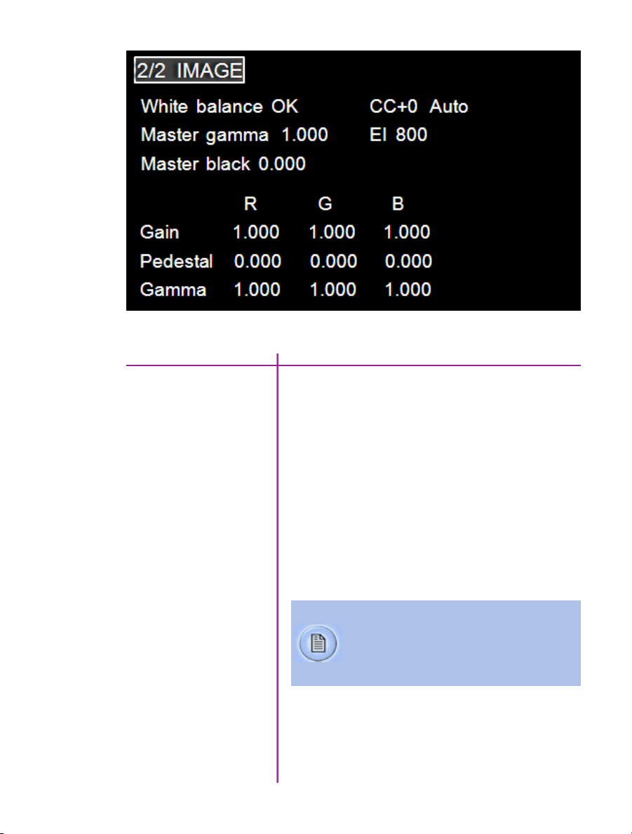
Most of the settings in this menu pertain to color cameras only.
image menu
White balance
CC+0
A White Balance process is used to balance the active
pixels of the image sensor to the overall color temperature
of the lighting.
1. Point the camera towards an area that represents
white, or place a white object in front of the
camera. Ensure that the white subject is not
fully saturated.
2. Select and highlight “OK” next to the word
“White Balance”.
3. Rotate the Menu knob to select a white balance
value, and press again.
Color temperature adjusts the red and blue
components of white balance, while Color
Compensation (CC+0) adjusts the magenta and
green components of the white balance.
Color Compensation is automatic, however it can be
further adjusted if necessary.
49
Chapter 6: On-Screen Displays
Page 56

Master gamma
EI
Gamma is the nonlinear relationship between signal
level and brightness output of pixels, (a small signal
level change at low voltage produces a larger variation
in brightness than the same change in level at high
voltage). A linear gamma would have the value of 1.0.
The camera’s default gamma setting is 2.2, which is a
standard compensation for most video monitors.
EI (Exposure Index) is a reference value for the ISO
level of the current shooting settings. A camera’s default
EI value is measured at the default gamma of 2.2.
Increasing the gamma will also increase the EI, and
decreasing the gamma to a minimum value of 1.0
will decrease the EI. The EI can also be adjusted by the
adjusting the EI value itself, using the on-camera controls,
as indicated here. Increasing the EI adds gain to the video
image, the more gain that is added the more digital noise
will be visible in the resulting cine. Vision Research
recommends maintaining the EI as close to default
as possible for best image quality.
Master black
Gain (R, G, B)
Pedestal (R, G, B)
Gamma (R, G, B)
50
Phantom Ultrahigh-speed Camera Manual
The Master black (Pedestal) parameter is used to
change the voltage level corresponding to black or
to the maximum limit of black peaks.
The gain can be adjusted in three separate color channels,
red, blue, and green.
The pedestal can be adjusted in three separate color
channels, red, blue, and green.
The gamma can be adjusted in three separate color
channels, red, blue, and green.
Page 57

capture screens
Capture Screen
Post Trigger Recording Screen
The on-secreen display information for the ‘Capture’
screen, and the ‘Post Trigger Recording’ screen, are the
same as the ‘Live Preview’ display except for the camera
state designators.
An empty red circle indicates the camera is recording
to internal memory (RAM), and awaiting a trigger signal.
Displays a ‘Live’ image on the video monitor.
A full red circle indicates the camera has been triggered,
and is filling internal memory (‘Post-Trigger’ frames).
Displays a ‘Live’ image on the video monitor.
51
Chapter 6: On-Screen Displays
Page 58

A B C D E F G
H
I
J K
cine stored screen
52
Phantom Ultrahigh-speed Camera Manual
Page 59

Camera State
A green square indicates the recording has ended, and
A
a cine is stored in internal memory.
Mark-In Point
Trigger Frame
Mark-Out Point
Number of Frames Available
Recording Duration
Time Stamp
Frame Rate
Serial Number / Name
Exposure Time
Resolution
Indicates the user-defined start point, (the first frame),
B
of the cine to be saved.
Indicates the frame the camera detected a trigger
C
signal at when capturing the cine.
Indicates the user-defined end point, (the last frame),
D
of the cine to be saved.
Indicates the number of frames recorded in the
E
camera’s internal memory.
Indicates the total length of recording time (in minutes
F
and/or seconds).
Indicates the day of the year/hour:minute:second:
G
microsecond.
Indicates the user-defined frame rate.
H
Indicates the camera serial number or user-defined
I
camera name.
Indicates the user-defined Exposure Time
J
(in milliseconds or microseconds).
Indicates the user-defined resolution (width x height),
K
in pixels.
53
Chapter 6: On-Screen Displays
Page 60

A B
C
The Playback’ screen includes all the on-screen display
information shown in the ‘Cine Stored’ screen along
with the following additions:
Cine Number
Frame Position Indicator
playback screen
54
Phantom Ultrahigh-speed Camera Manual
Cine List
The Cine Number indicates the cine selected via the
A
Cine List to review, edit, and/or save.
The white square, below the internal memory ‘time line’
B
represents where the frame being displayed is located
within the internal memory buffer or attached Phantom
CineMag
The Cine List displays the list of cines the end user can
C
select to review, edit, and/or save.
Page 61

The ‘Play Cine Options’ screen includes all the on-screen
display information displayed in the ‘Playback’ screen
along with the following additions:
Save
Set In
Set Out
Forward
play cine options
Reverse
Back
Used to save the cine to an attached CineMag IV.
Defines the new start point of the selected cine file.
Defines the new end point of the selected cine file.
Plays the selected cine in the forward direction.
Plays the selected cine in the reverse (backward) direction.
Returns the display screen to the ‘Playback’ screen.
55
Chapter 6: On-Screen Displays
Page 62

Phantom CineMag IV
Indicators
On the back of the Phantom CineMag IV are a number
of LED indicators that show the current Phantom
CineMag IV status.
Mag Capacity Indicator:
When a Phantom CineMag IV
is empty, all LEDs will be
illuminated. As material
is recorded to the mag,
the LEDs will turn off.
The last LED will always
stay on to indicate power.
Erase protect switch:
When the erase-protect switch is
in the lock position, the CineMag IV
cannot be erased. Use an appropriate
tool, such as a micro-flathead
phantom cinemag iv
screwdriver to flip the switch.
56
Phantom Ultrahigh-speed Camera Manual
Activity LED:
Green for read activity
Red indicates recording
Orange indicates erasing
Page 63

Phantom CineMag IV
7
Introduction
& CineStation IV
The Phantom CineMag IV is a high-speed solid-state
storage module, compatible with all Phantom Ultrahigh-speed Series - 12 cameras for recording. Cines
can be downloaded from the CineMag either through the
camera body itself, or through a CineStation IV. It records
raw sensor data in 10-bit packed format, and differs
significantly from a traditional hard drive or solid state
disk in that there is no file system.
For high-speed recording, you must record to the
camera’s RAM buffer first, review, and then transfer to
the CineMag - this is known as ‘Loop’ mode. For lower
speed recording, the camera can run in Run/Stop mode,
writing direct to the CineMag, allowing several minutes
of recording. .
It is not possible to delete individual clips from a CineMag
IV because all frames are recorded contiguously. This is
an important consideration when saving clips – once the
CineMag is full; you can only re-record on it by deleting
its entire contents. For this reason it’s recommended that
RAM cines are reviewed and trimmed by setting in and
out points prior to transfer from the RAM buffer to the
CineMag.
Phantom CineMag IV
and Previous Generations
of CineMag
.cine files are downloaded over Ethernet (either 1Gb or
10Gb) using Windows-based Phantom PCC.
There have been a few generations of Phantom CineMags.
The Phantom CineMag IV has higher capacity than the
first generations of Phantom CineMag and CineMags II.
These earlier generations are not compatible with the
Phantom Ultrahigh-speed v2512, v2012, v1612, and
v1212 cameras.
57
Chapter 7: Phantom CineMag & CineStation IV
Page 64
Attaching a CineMag IV
The Phantom CineMag IV slides into the top compartment
of the camera, as pictured, an the door latches shut.
Ensure the CineMag slides in evenly and mounts securely.
Removing a CineMag IV
Saving from a CineMag IV
58
Phantom Ultrahigh-speed Camera Manual
To remove the Phantom CineMag IV, pull the red tab on
the slide door, and pull the CineMag out of the camera.
The CineMag IV is hot-swappable, and the camera can
remain on during this procedure, but ensure the camera
is not writing or reading from the CineMag before
removing it.
Vision Research recommends that you save the clips
from a Phantom CineMag IV as Cine Raw files, even
though it is possible to save them in a number of file
formats. Cine Raw files not only preserve all the metadata
of the clip (such as frame rate, shutter speed, timestamps,
etc.) it will also be the fastest and best-quality format.
Page 65

The 10-bit ‘Packed’ format is the default when saving
Cine Raw files from a CineMag IV. This results in smaller,
more manageable files than the 12-bit ‘unpacked’ format,
and with no quality loss. If you are using 3rd party post
production software to read the Cine Raw files, please
ensure they are compatible with this ‘packed’ format.
To save the Cine Raw in an unpacked format, simply
un-check the ‘Packed’ box prior to saving.
Saving an Individual Cine
from a CineMag IV
From the ‘Play’ tab in PCC, select the cine you want to
save from the ‘Cine:’ pull-down menu. You will see all
clips in the RAM as well as the CineMag in this list. Once
you’ve selected a clip, you can mark an in and out point if
desired by clicking the ‘[‘ and ‘]’ buttons respectively.
Alternatively, use PVP software in a similar manner when
using video playback from the camera body.
Then click the green ‘Save Cine…’ button.
In the ‘Save Cine’ dialog box, choose ‘Cine Raw’ as the file
format, navigate to the folder where you wish to save the
clip and click ‘Save.’
In the Play Tab, click the triangle to the right of the
‘Save Cine…’ button, and from the popup menu select
‘Save All Flash Cines To File.’
In the subsequent save dialog window, navigate to the
folder where you wish to save the clips, and select the
‘Cine Raw’ file format. Choose a name for the group of
Cine files and click the ‘Save’ button. Each Cine’s file
name will start with the name you choose, and end with
the cine number.
Selected Cine Files
from a CineMag IV
In the PlayTab, click the triangle to the right of the
‘Save Cine…’ button, and from the popup menu select
‘Select&Save Cines to File.’
In the pop-up window, select the cines you wish to save.
Use the shift key to select a range of clips, or the control
key to add individual clips. When you’ve
59
Chapter 7: Phantom CineMag & CineStation IV
Page 66

selected the cines you want to save, click ‘OK.’ In the
subsequent save dialog, navigate to the folder where you
wish to save the clips, and select the Cine Raw file format.
Choose a name for the clips and click the ‘Save’ button.
‘_Flashcine#’ will be appended to the file name
of all batch-saved clips, where ‘#’ represents
the number of each take.
Erasing a CineMag IV
Erase Protection
A CineMag IV can be erased via the Phantom PCC and
PVP software from the camera or CineStation IV.
In PCC software, navigate to the ‘Live>Flash Memory’
menu and click the ‘Erase’ button. Confirm that you wish
to delete all clips.
In PVP software, simply tap the ‘Erase All’ button, and
confirm. Erase progress is indicated on the video OSD,
on the camera screen, and by a progress bar in the
software.
A 1TB CineMag IV will take about 2.5 minutes
to erase, and a 2TB CineMag IV will take up to
5 minutes to erase.
Once complete, all data on the CineMag IV will be erased,
and the CineMag will be ready for recording again right
away.
In order to protect the contents, there is a tiny erase
protect switch on the front of the CineMag IV. When
locked, the CineMag can be recorded to, but not erased.
If you find it impossible to erase the CineMag check that
the erase protect switch is in the unlocked position.
60
Phantom Ultrahigh-speed Camera Manual
Page 67
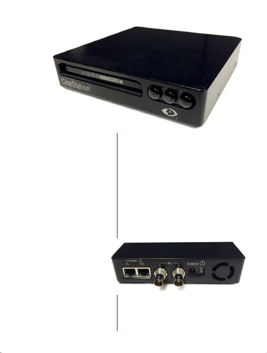
Phantom CineStation IV
The CineStation IV is a simple device meant to quickly and
efficiently download the contents of a CineMag IV. When
connected to a computer running Phantom software,
a CineStation behaves almost identically to a camera,
except that no capture or live functions will be enabled.
There are two 3G SDI video ports on the back of the
CineStation IV, with video buttons on the front.
These video ports and buttons pictured here are not
active.
phantom cinestation iv
61
Chapter 7: Phantom CineMag & CineStation IV
Page 68

Connecting a CineStation IV
to Phantom Software
10G Network Settings
The CineStation IV is available with a 1Gb and 10Gb
Ethernet port. The 1Gb network works with the same
settings needed for a Phantom camera:
Network IP 100.100.100.1
Subnet: 255.255.0.0
Ensure no firewalls or virus protection is enabled
To use the CineStation IV with a 10G connection, connect
a CAT 6A (or greater) cable from the 10Gb Ethernet port
on the CineStation IV to an approved 10Gb NIC (Network
Interface Card) in the host computer, and use the following
network settings:
10G Network IP: 172.16.0.1
Subnet: 255.255.0.0
The Phantom software will automatically detect the IP
address of the CineStation IV. If you need to manually
connect to the CineStation IV, its IP address is printed on
the side of the device, label XIP.
While most modern 10GBASE-T interface card installed
in a PC should work, we have been using and testing the
interface with the Intel X540-T1 and X540-T2 cards and
find them to be very reliable.
62
Phantom Ultrahigh-speed Camera Manual
Once the NIC is installed in the PC, ensure the latest driver
is installed from the manufacturer’s website. Generally,
the computer and all devices must be re-booted after the
driver installation.
Certified Phantom 10G Ethernet drivers need to be
installed through PCC software. The Phantom Installer
will prompt the user to install the Phantom10G Ethernet
drivers.
For optimum results, ensure there are no bottlenecks
in the system - a striped RAID is recommended for the
fastest save speeds.
Page 69
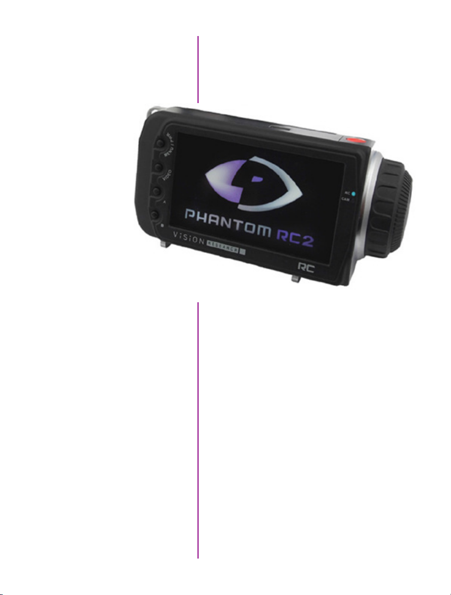
Phantom Remote
8
Control Unit
The Phantom Remote Control Unit (RCU) is a small,
lightweight, hand-held controller which allows you to
adjust most settings on your camera as well as view and
save recorded cines to the CineMag. The RCU is available
in both wired and wireless versions. Both versions will
connect with an included 5 meter cable direct to the back
of the camera. Alternatively, the wireless model includes
a Bluetooth dongle that allows for operation from up to
100 meters.
The 5" active TFT display is easy to use – even outdoors.
The display can act as an HD-SDI video monitor, a
fullfeatured touch-screen controller, or both. An SDI
cable connection is required to view the HD-SDI output
of the camera on the RCU screen. Video is not transmitted
via Bluetooth.
Chapter 8: Phantom Remote Control Unit
63
Page 70
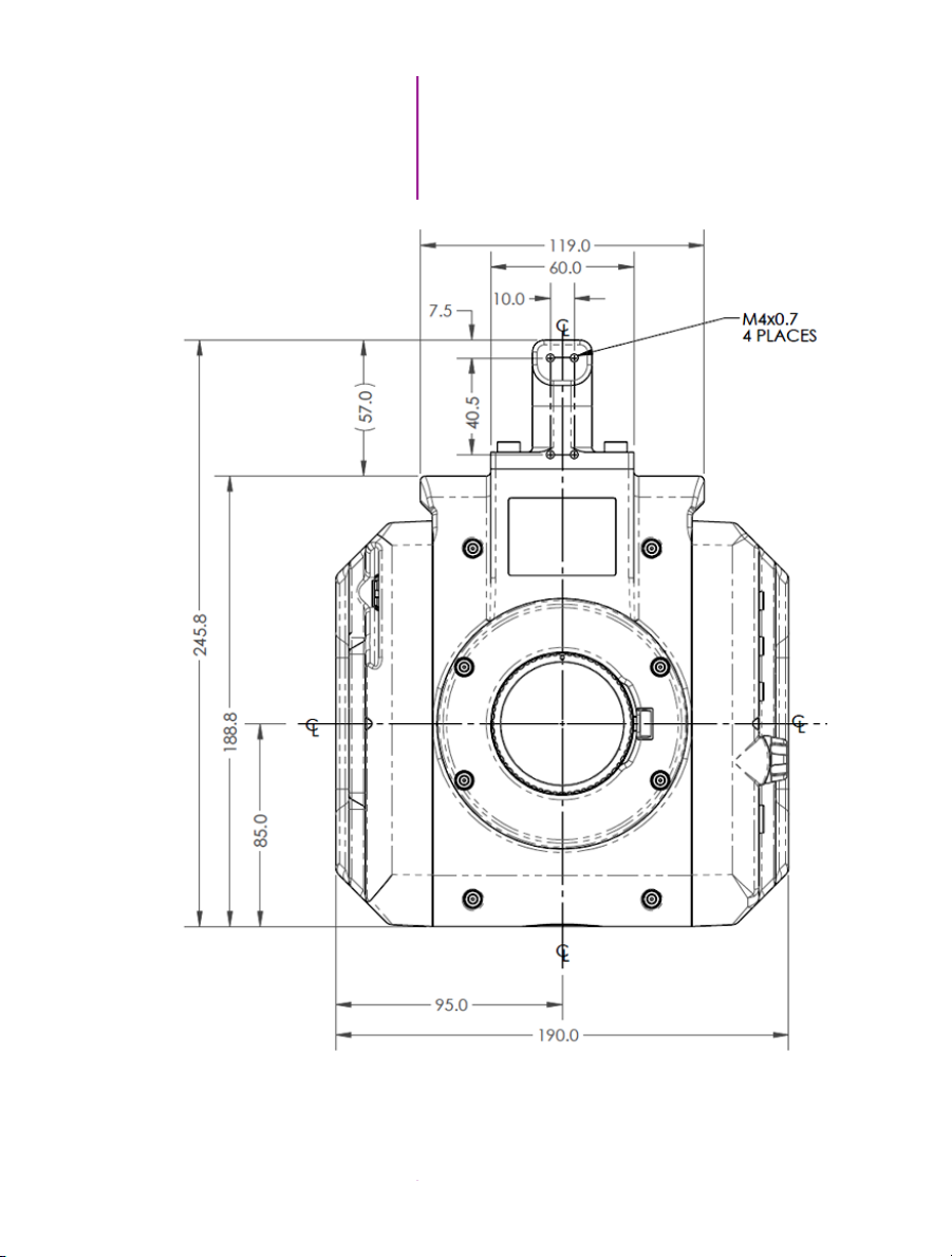
mechanical drawings
64
Phantom Ultrahigh-speed Camera Manual
Front View
(with / without CineMag)
Page 71
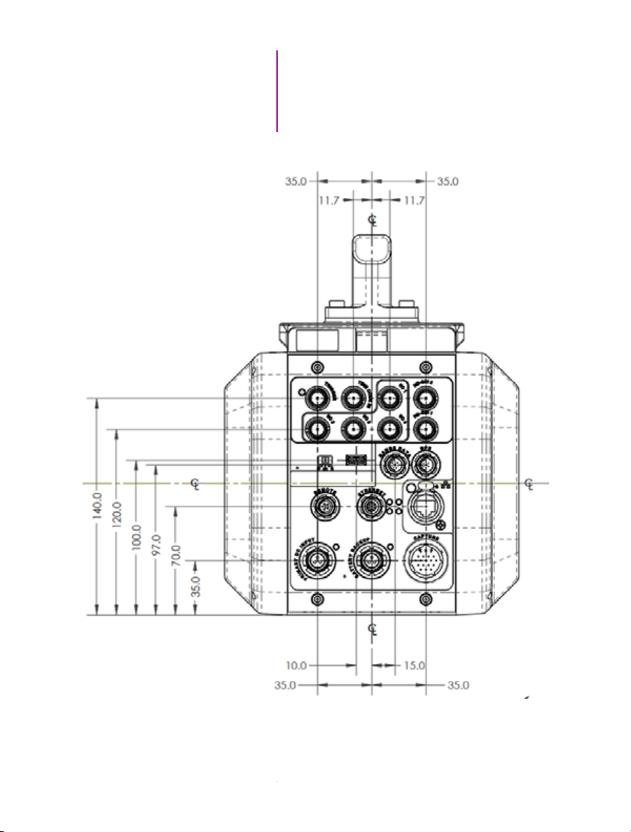
9
Support
Rear View
(with / without CineMag)
Chapter 9: Support
65
Page 72
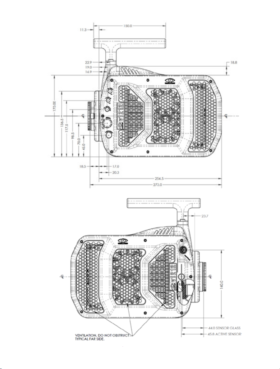
Left Side View
(without CineMag)
Right Side View
(without CineMag)
66
Phantom Ultrahigh-speed Camera Manual
Page 73

Left Side View
(with CineMag)
Right Side View
(with CineMag)
67
Chapter 9: Support
Page 74
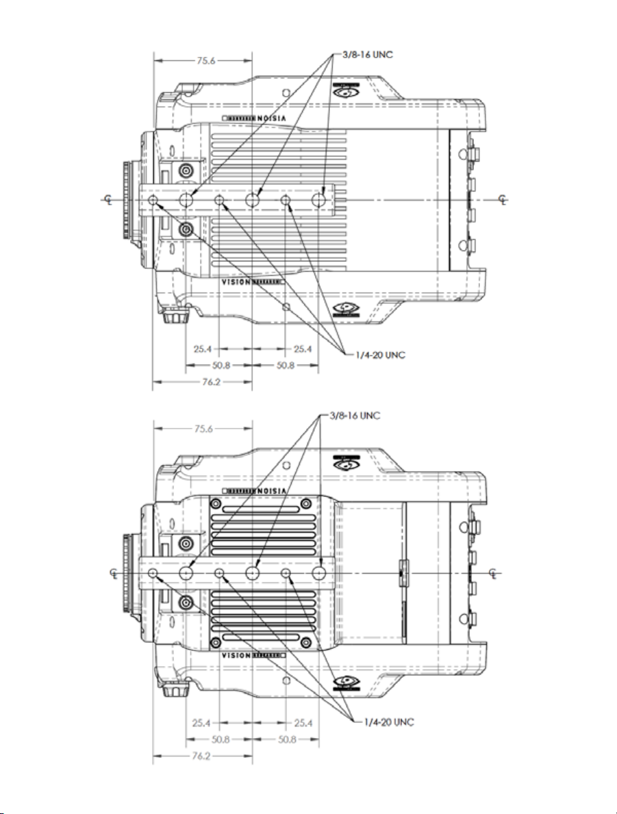
Top View
(without CineMag)
Top View
(with CineMag)
68
Phantom Ultrahigh-speed Camera Manual
Page 75

Bottom View
(with / without CineMag)
69
Chapter 9: Support
Page 76

Use these schematics to build custom cables at your own risk. Mis-wired cables
can cause serious damage to the camera, which is not covered under warranty.
Vision Research recommends only using cables supplied by Vision Research.
These pin-out diagrams refer to the connector on the camera body. Part numbers
indicated are for the cable’s connector.
Phantom vxx12
BNC Connectors
I/O Signal ports
BNC
NOMENCLATURE / FUNCTION
Trigger Trigger-In / Isolated Input. Active low. Can be
Time Code In Timecode In / can accept IRIG-B and SMPTE
I/O 1 Ready / Isolated collector output with 1k pull-up.
I/O 2 F-Sync / +5V maximum threshold, input is also
I/O 3 Timecode Out / for IRIG-B or SMPTE
I/O 4 Strobe / Isolated collector output with 1k pull-up.
HD-SDI
1 & 2
activated by a switch to ground. The trigger pulse
needs to be at least 3 microseconds long.
standards.
compatible with TTL levels and must be a properly
terminated, (50-ohms).
timecode.
Two HD-SDI ports can acts as identical 4:2:2
HD-SDI ports with one set up to provide an
optional) on-screen display to monitor the
on-camera controls and cameaa operation.
Or, they can be configured as a ‘single 4:4:4
Dual-Link HD-SDI port.
connector pinouts
70
Phantom Ultrahigh-speed Camera Manual
Page 77

Phantom vxx12
Range Data Connector
Range Data port
8-pin Fischer part # S103.Z058
PIN NOMENCLATURE / FUNCTION
1 GND / Power Ground
2 ROUT+ / Remote/Range Data Out (Positive),
(RS-422); +5V maximum. Depending on data
transmission rates, RS-422 can be used at distances
to 4,000 feet (1,275 meters).
3 ROUT- / Remote/Range Data Out (Negative), (RS-422);
+5V maximum. Depending on data transmission rates,
RS-422 can be used at distances to 4,000 feet
(1,275 meters).
4 RIN+ / Remote/Range Data In (Positive), (RS-422);
+5V maximum. Depending on data transmission rates,
RS-422 can be used at distances to 4,000 feet
(1,275 meters).
5 RIN- / Remote/Range Data In (Negative), (RS-422);
+5V maximum. Depending on data transmission rates,
RS-422 can be used at distances to 4,000 feet
(1,275 meters).
6 +3V3R
7 +24VR
8 GND / Power Ground
Phantom vxx12
GPS Connector
GPS (Ground Positioning System) port
6-pin Fischer part # S103Z056
PIN NOMENCLATURE / FUNCTION
1 GND / Power Ground
2 RxD / RS-232 Receive Data
3 Unused
4 +5V/0.2A / +5VDC (Direct Current) positive power to the
Phantom camera at 0.2 amps.
5 pps In / Parts-per-Second In
6 pps Ground / Parts-per-Second Ground
71
Chapter 9: Support
Page 78

Phantom vxx12
Remote Connector
Remote port (for Phantom RCU)
5-pin Fischer part # S103.A054
PIN NOMENCLATURE / FUNCTION
1 +24VDC
2 PNG / The power input and the acquisition control sig-
nals are isolated from the camera system ground. This
isolation is designed to avoid system ground loops only,
and should not be subject to high voltages.
3 XRXD / Receive Data (RS-232); +5V maximum, normally
limited to 50 feet (16 meters).
4 XTXD / Transmit Data (RS-232); +5V maximum, normally
limited to 50 feet (16 meters).
5 IOGND2 / RS232 Ground - All the serial ports are not
isolated (referred to system ground). As such, they
should only be connected to properly earthed equipment.
Phantom vxx12 Power Connector
(Primary / Battery Backup)
72
Phantom Ultrahigh-speed Camera Manual
Power ports
3-pin Fischer part # SS 104Z040-80
PIN NOMENCLATURE / FUNCTION
1 +20 - 28 Volts DC
2 CHGND / Chassis Ground
3 GND / Power Ground
Page 79

Phantom vxx12
GigE Ethernet Connector
GigE Ethernet port
8-pin Fischer part # SS 103 A058-130
PIN NOMENCLATURE / FUNCTION
1 ETHRXP / 10/100/1000BASE-T Ethernet Receive
(positive)
2 ETHRXN / 10/100/1000BASE-T Ethernet Receive
(negative)
3 ETHTXP / 10/100/1000BASE-T Ethernet Transmit
(positive)
4 ETHTXN / 10/100/1000BASE-T Ethernet Transmit
(negative)
5 MDI2P /10/100/1000BASE-T Media
Dependent Interface 2 (positive)
6 MDI2N / 10/100/1000BASE-T Media
Dependent Interface 2 (negative)
7 MDI2P / 10/100/1000BASE-T Media
Dependent Interface 3 (positive)
8 MDI3N / 100/1000BASE-T Media Dependent
Interface 3 (negative)
Phantom vxx12
10GigE Ethernet Connector
10GigE Ethernet port
8-pin RJ45
PIN NOMENCLATURE / FUNCTION
1 XMDI0+ / MDI 0 (positive)
2 XMDI0- / MDI 0 (negative)
3 XMDI1+ / MDI 1 (positive)
4 XMDI2+ / MDI 2 (positive)
5 XMDI2- / MDI 2 (negative)
6 XMDI1- / MDI 1 (negative)
7 XMDI3+ / MDI 3 (positive)
8 XMDI3- / MDI 3 (negative)
MDI - Media Dependent Interface
73
Chapter 9: Support
Page 80

Phantom vxx12
Capture Connector
Capture port
19-pin part # PTO6A-14-19S
PIN NOMENCLATURE / FUNCTION
A Event-In / active-low isolated input; signal must be active
when strobe is high, and be 30μs long minimum.
B Trigger / Isolated Input. Active low. Can beactivated
by a switch to ground. The triggerpulse needs to be at
least 3 microseconds long.
Capture cable = Red
C Strobe Out / Isolated collector output with 1k pull-up.
D IRIG- In (Unmodulated) / IRIG-B timecode input.
Capture cable = White
E IRIG GND
F Video Out (Composite) / Standard (non-isolated)
75-ohm output level.
Capture cable = Green
G Video GND (Composite) / Ground / Shield
(for signals: F, and T).
H Serial (RS-232) Ground / Should only be connected
to properly earthed equipment (Serial ports are not
isolated).
J Chassis GND /
K Transmit Data (RS-232) / standard RS-232 level.
L +12-30VDC / DC output (0.5A amp Max.) Typically used
to power break out boxes.
M Power GND / isolates power input and acquisition control
signals from system ground to avoid system ground
loops only, and should not be subject to high voltages.
N Auto-Trigger Output / Pulled low when an auto-trigger
condition detected.
Capture cable = Black
74
Phantom Ultrahigh-speed Camera Manual
Page 81

Capture port (continued)
PIN NOMENCLATURE / FUNCTION
P ISO GND / Ground / Shield (for signals: A, B, C, R, and V)
R Pre-Trigger In / MemGate In
Pre-Trigger In / Places camera into the ‘Ready’ state or
‘Capture’ mode with dtection of TTL (falling edge) pulse.
Mem-Gate In / Active-low isolated input.
Capture cable = Red
S IRIG Out (Unmodulated) / IRIG-B timecode output.
Swings to RS-232 levels of +/- 9V
Capture cable = Blue
T GenLock / Synchronizes playback to a properly
terminated (75-ohm) video signal (not exceeding +1.56V
maximum), utilizing a composite video inbound signal,
or synch live video, by synchronizing the SDI outputs
to the GenLock signal.
U Receive Data (RS-232) / standard RS-232 level.
V Ready / Isolated collector output with 1k pull-up.
Phantom vxx12
Viewfinder Connector
Component VF port
7-pin Fischer part # S103.A057
PIN NOMENCLATURE / FUNCTION
1 GND / Power Ground
2 GND / Power Ground
3 PB HD Blue Channel
4 PR HD Red Channel
5 Y HD Green Channel
6 GND / Power Ground
7 +12V Positive 12 VDC / 1.5 Amp
75
Chapter 9: Support
Page 82

What is the difference
between ‘Native’ and
‘Cropped’ resolutions?
To simplify things, only specific resolutions are available
from the camera menu. The choices are a variety of
common resolutions and aspect ratios.
The resolution controls in PCC software are somewhat
different, and allow more flexibility in choosing how the
images are captured and output. First, the native
resolution must be selected from the ‘Cine Settings /
Resolution’ pull-down, however an output resolution
can be set using the ‘Geometry & Overlays’ section
of the ‘Image Tools’ menu.
sensor solutions
76
Phantom Ultrahigh-speed Camera Manual
There are a variety of pre-set output resolutions available,
or any value can be typed in and offset with the X & Y
coordinates listed. Cropped or scaled resolutions set
on the camera body will automatically set the ‘Crop &
Resample’ parameters appropriately.
Page 83
Cine Raw files saved from PCC software will maintain
the full native resolution, with the crop/resample settings
‘The PCC ‘Image Tools /
Crop & Resample’ menu
is also a powerful way to
manipulate saved Cine file
prior to exporting the files
to a different format.
flagged in metadata.
Exporting those files in a format other than Cine Raw
(like .mov or .dpx) will apply the settings, and the resulting
files will be at the intended cropped and/or resampled
output resolution.
Cine Raw files that have been flagged with crop/
resample metadata can still be exported at the full
captured resolution by turning off the Crop & Resample
options in PCC’s Image Tools menu.
Supported Resolutions
v2512 v2012 v1612 v1212
Width x Height Max FPS Max FPS Max FPS Max FPS
1280 x 800 25,600 22,500 16,600 12,600
1280 x 720 28,500 25,100 18,400 14,000
1024 x 800 30,500 26,900 19,700 15,000
1024 x 512 47,300 41,800 30,700 23,400
896 x 800 33,600 29,800 21,800 16,600
768 x 768 39,100 34,700 25,300 19,300
640 x 480 69,900 62,400 45,500 34,700
512 x 512 75,400 67,700 49,100 37,500
512 x 384 99,500 89,000 65,000 49,60
385 x 256 170,600 154,200 112,300 85,700
256 x 256 205,00 187,200 135,400 103,600
256 x 128 375,700 343,500 253,00 193,900
128 x 64 764,700* 708,800* 538,400 415,500
128 x 32 1,000,000* 1,000,000* 840,000* 653,00*
128 x 16 1,000,000* 1,000,000* 1,000,000* 820,000*
* Assumes FAST Option is installed
Maximum v2512 standard; 677,000 fps
Maximum v2012 standard; 666,000 fps
Maximum v1612 standard; 646,000 fps
Maximum v1212 standard; 570,000 fps
Chapter 9: Support
77
Page 84

difference between
the Phantom UHS-12
Series (v2512, v2012,
v1612, and v1212) and
the previous UHS-11
faqs
Series (v2511, v2011,
v1611, and v1211)?
What is the
The UHS-12 Series are similar to the UHS-11 Series,
except for two differences. The first difference is the
increase in memory. The UHS-12 Series can be equipped
with either 72GB, 144GB, or 288GB of RAM. The second
difference is that the UHS-12 Series take advantage of
the CineMag IV, with 1TB or 2TB of non-volatile memory.
These enhancements are designed to make capturing,
accessing, and managing your critical data much easier.
The UHS-12 Cameras have the same excellent sensitivity
and framerates as the UHS-11 cameras, with the same
Phantom Features and outstanding image quality you’ve
come to expect from Phantom digital high-speed cameras.
The v2512, v2012, v1612,
and v1212 all have
10Gb Ethernet interface.
Tell me more about it
and how to use it.
Can I use a viewfinder with
the Phantom v2512,
v2012, v1612, or v1212?
Yes, a copper UTP 10Gb Ethernet interface is standard
on the camera. When properly configured, this allows for
cine downloads at speed up to 4 or 5 times that of the
Gb Ethernet interface. While any compatible 10GBASE-T
interface card installed in a PC should work, we have been
using and testing the interface with the Intel X540-T1 and
X540-T2 cards and find them to be very reliable.
Vision Research provides a ruggedized connector carrier
to be used when connecting a standard CAT6 or CAT6A
Ethernet cable between the camera and the interface
card. The customer must supply the appropriate cable.
A CAT6A cable is recommended and gives you a
maximum 100m distance between the camera and the
interface card. (A CAT6 cable is limited to 50m.)
Additional information is available in a Phantom Note
named “10Gb Ethernet Solutions for Phantom
Cameras and Accessories” and can be found at:
http://www.visionresearch.com/Service--Support/
Downloads/Documents/Technical-Notes/
Yes. In fact, there is a viewfinder port on the camera that
will supply video and power to a viewfinder or monitor. All
UHS-12 digital cameras come with a 280W power supply,
providing ample power for a camera with maximum
288GB memory, a 2TB CineMag, and the viewfinder
78
Phantom Ultrahigh-speed Camera Manual
Page 85

What signals are available
on the Capture Connector,
on the back of the camera,
and which of those are provided
on the standard Capture Cable
that ships with the camera?
There is a 19-pin Amphenol connector on the back of
the camera that is called the Capture Connector. The
connector has the following available signals:
• Event input (an external signal can “mark” one or
more frames with an event marker making it easy
to later find and view specific frames)
• Trigger input (provides a hardware trigger to the
camera)
• Strobe output (is a low during the frame exposure
time)
• Ready output (is high when the camera is capturing
pretrigger frames)
• IRIG-In (external sync and time stamping from a
modulated or unmodulated IRIG source)
• IRIG-Out (provides an unmodulated IRIG source that
contains timing information from the camera)
• Video Out (a composite video signal, either NTSC
or PAL)
• Serial Port input (for serial protocol control of
camera)
• Power Out (24VDC, used to power the Break-out-
Box)
• A-Sync output (optionally, signal goes low when
a trigger event is detected by the Image-Based
Auto-Trigger feature allowing for multiple cameras
to be synchronized to an event trigger)
• Pre-trigger/Memgate input (mode is set in software;
if Memgate is low, acquired frames are discarded
rather than saved to camera memory; Pre-trigger
signal “arms” the camera and starts the acquisition
of pretrigger frames)
Detailed information about these signals is available using
the PCC application’s Help feature.
Chapter 9: Support
79
Page 86

All v2512, v2012, v1612 and v1212 cameras ship with
a standard Capture Cable that connects to the Capture
Connector and provides access to:
• Ready
• Strobe
• A-Sync
• Pre-trigger/Memgate
• Video
All other signals are accessible by using a Phantom
Break-out-Box. See the related FAQ.
Can I use any Vision Research
power supply with the v2512,
v2012, v1612, and v1212?
I have a power supply
from a UHS-11 Series
camera, can I use it?
What does the AUTO/ON/OFF
switch do?
No, you must use the 280W power supply shipped with
the camera. It is part number: VRI-PWR-SUPPLY-280WFIS. Spares and replacement power supplies are available
from Vision Research.
Prior to the introduction of the Phantom UHS-10 Series
(the predecessors to the UHS-11 and UHS-12 Series),
Phantom cameras did not have a physical power switch.
Instead, the camera powered up any time an appropriate
DC voltage appeared on the power input to the camera.
This was done so that cameras can be powered up
(booted) remotely by providing primary power and did
not require physical access to the camera.
However, there is a physical power switch on the v2512,
v2012, v1612 and v1212. It has three positions: AUTO,
ON, and OFF.
When the switch is set to AUTO, providing power to the
Primary DC Input will power up (boot) the camera and it
will be ready for use. In AUTO, providing power to the
Battery Backup power input of an unpowered camera
WILL NOT power up the camera. However, if there is a
loss of primary power, then the Battery Backup power
will be used to maintain camera operation and protect
any stored data.
80
Phantom Ultrahigh-speed Camera Manual
Page 87

When the switch is in the OFF position, the camera is off.
Providing power to the Primary DC Power input or the
Battery Backup input will not cause the camera to
power-up.
When the switch is moved to the ON position, the camera
will power-up immediately provided there is power
connected to the Primary DC Power port OR the Battery
Backup port on the camera
There are several use-cases this scheme enables:
1. Battery backup for mission critical tests:
Set the camera to AUTO. Power through the
Primary input and provide local battery backup
power to the Battery Backup input. If primary
power is lost, camera operation will continue and
data is protected by the battery backup.
2. Remote power up: You can turn the camera on by
providing power to the Primary DC Power input
when the camera is in AUTO or ON.
3. Remote power cycle: If the camera will need to
have power cycled remotely, set the switch to
AUTO and do not use a battery for battery backup.
Will the liquid in the heat
pipes freeze and damage the
heat pipes if the camera
is stored or transported at
temperatures below zero?
What is the worst case
power draw of the camera
that I would use to calculate
battery requirements?
Battery operation: Connect a battery to the Battery Backup
port. Set the switch to ON.
There is no danger. First, there is actually very little liquid
in the heat pipe. And, it is under very low pressure. So,
while the liquid might freeze, it will not damage the heat
pipe. Soon after powering the camera, the liquid will thaw.
You should assume the camera will consume 240 watts.
This assumes that you are not using a viewfinder with the
camera, but that it has a CineMag and full memory.
81
Chapter 9: Support
Page 88

I see there are two power
inputs ports. One is the Primary
DC Power and the other is
Battery Backup.
How do these work?
The primary input is where you plug the 280W A/C power
supply provided with the camera. This is your primary
source of power for the camera. You can optionally
connect a backup source of power–often a battery–to the
backup battery power input. If the camera power switch is
set to AUTO, and if there is a loss of power on the primary
input, even momentarily, the backup power will immediately take over - providing uninterrupted power to the
camera. This is important to protect any images stored in
the camera’s high-speed memory from accidental loss.
Connecting power to the battery backup port will not turn
on the camera. (See FAQ about the AUTO/ON/OFF switch.)
There is no drain from the connected battery unless a loss
of primary power causes the power input to switch to the
battery backup.
The battery backup port will not charge a connected
battery.
In case of primary power loss, the backup battery port
will not only protect images saved in memory, but can
provide sufficient power to power all camera operations
until the input voltage drops below the minimum required,
~ 18VDC.
If primary power is restored, that again becomes the
power source for the camera and the battery port reverts
to a backup mode.
Tell me more about the GPS port
on the back of the camera.
82
Phantom Ultrahigh-speed Camera Manual
The GPS port on the Phantom v2512, v2012, v1612
and v1212 can be used to provide date, time and
location information from the GPS satellite network.
Vision Research sells a compatible GPS receiver
(VRI-GPS-18X-LVC-5M). With the GPS receiver
connected to the camera, and assuming it has a valid
satellite fix, GPS timing can be used similarly to IRIG
timing. You can synchronize the camera’s internal clock to
the GPS, timestamp frames with GPS timing accuracy, and
even save the camera’s latitude and longitude with any
cine file (location error is < 3 meters after a satellite fix.)
The GPS connection supplies 5 volts at 0.2 A maximum,
and an RS-232 connection to a GPS device.
1 PPS pulse is used for timing in the camera.
Page 89

These camera have alot of
memory in them! How long does
it take to save a shot from
these cameras?
Communication with the device is at 4800 baud over the
NEMA 0183 standard protocol which is very common.
The GPS position is recorded in the Cine header file.
Connection diagram is available.
All of the Phantom Ultra High-Speed Cameras (v2512,
v2012, v1612 and v1212) are equipped standard with
10GB Ethernet and can be equipped with the unique
CineMag interface, precisely for fast downloading.
The 10GB Ethernet allows data transfer at up to 500 MB/
second on optimized systems, meaning all 288GB of
memory can be downloaded in approximately 8 minutes.
The CineMag interface can transfer images from the
camera’s high-speed memory to non-volatile, flash
memory at about 1Gpx/sec. A full resolution frame is
1 Mpx, so you can save about 1000 frames each second
to a CineMag. Or, another way to state this is you can save
about 1.5GB/sec to non-volatile mass-storage. A Phantom
Ultra High-Speed Camera, equipped with maximum
memory of 288GB, can save its full memory buffer to
a CineMag in just over 3 minutes.
Once a shot is saved to the CineMag it is safely
stored and available for later retrieval. This means you
immediately can use the camera for another shot.
Images stored on a CineMag are available for later
retrieval using the Phantom Camera Control (PCC)
software with the CineMag mounted on either the camera
or the offline docking station known as a CineStation, and
may be downloaded either through the camera or the
CineStation, using their 10Gb Ethernet ports.
The v2512, v2012, v1612 and v1212 are only compatible
with CineMags IV’s, offered in 1TB and 2TB versions.
Is it true that a camera
that runs this fast must be
powered by either dilithium or
silithium crystals?
No. We’ve been able to achieve these rates of speed
without the use of such technology
83
Chapter 9: Support
Page 90

84
Phantom Ultrahigh-speed Camera Manual
Page 91

Page 92

Vision Research - Corporate Headquarters
100 Dey Road
Wayne, New Jersey 07470
USA
Ph: +1.973.696.4500
Toll Free: 800.737.6588
Fax: +1.973.696.0560
Vision Research - Florida Office
1002 Monterey Commons, Suite 200
Stuart, Florida 34997
USA
Ph: +1.772.286.7000
Fax: +1.772.286.6206
Vision Research Ltd. - UK
Suite F8, Bedford i-lab
Priory Business Park
Stannard Way, Bedford
MK44 3RZ, United Kingdom
Ph: +44 1234 834 850
Fax: +44 1234 834 851
w w w . v i s i o n r e s e a r c h . c o m
PN: ZDOC-64110-MA-0001 Rev 1
 Loading...