

Page 1

Page 2

*DISCONNECT BATTERY BEFORE INSTALLATION*
Page 3

Thank you for purchasing state-of-the-art electronics from Phantom Products. We hope you enjoy
Touch n Go as much as we have.
Please keep in mind that it is the responsibility of the purchaser / installer to determine if this system is
right for the intended application. It is also the responsibility of the purchaser / installer to observe
proper and safe installation procedures. For example; using the proper gauge of wires to make
connections, and installing a neutral safety switch between Touch n Go unit and Starter. Touch n Go
was designed for the easiest possible installation, but it is still recommended that you consult a
professional for assistance.
Please read and understand manual completely before using or installing your Touch n Go ignition
replacement system.
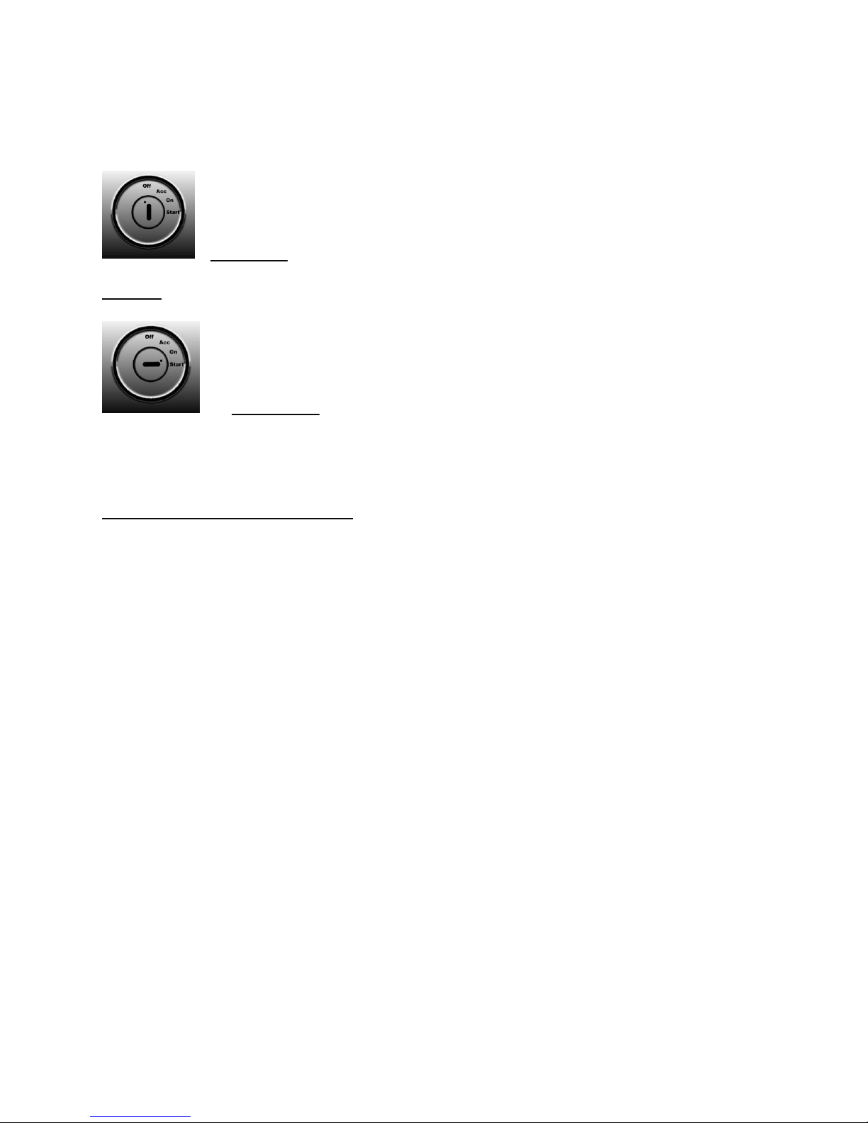
Button Function
You will notice icons in this section that resemble a keyed ignition. These are a representation of the
equivalent key position or function state Touch n Go is in.
Off position: Button will glow red in two different ways. A rapid flash, followed
by a one second pause, means that security is active and Touch n Go is disabled. Touch n Go will not
respond to touch input. This is because the security system (security optioned units only) has not
Page 4

detected the proper key fob, or the valet switch is in the off position. A slow fading red light, means
that Touch n Go is enabled and security is deactivated due to the presence of the proper key fob, or a
valet switch in the on position. Touch n Go will now respond to touch inputs. These different forms
of flashing red light are for visual indication of what particular sate of off Touch n Go is in.
Off state (off position) is reached two ways. One way is by cycling from Accessory position, (1st touch)
to On position, (2nd touch) to off (3rd touch) by briefly providing a touch input to the button. The other
way is to touch button for two seconds while engine is running to shut engine off, thus returning to off
state.
*Once engine off is triggered, accessory output stays on for ten minutes, or until door is opened*
Accessory position: Button will have a blue glow. Accessory output will be
activated. Anything hooked to Accessory output will be supplied with +12 volts.
1st Touch- Accessory output “active state” is reached by touching button briefly (with no brake input,
foot not on brake pedal) while button is slowly glowing red (showing Touch n go is enabled, but off).
Button will give visual indication of received input by switching to a blue glow, and only power
consumers connected to Accessory output will turn on, such as your vehicles radio for example.
Ignition position: Button will have a teal glow. Ignition output will be activated
in addition to accessory output. Anything hooked to these two outputs will be supplied with +12 volts.
2nd Touch- Ignition output “active state” is reached by touching button briefly (with no brake input,
foot not on brake pedal) while button is glowing blue (showing Touch n go is in Accessory “active
state”). Button will give visual indication of received input by switching to a teal glow, and all power
consumers connected to Ignition and Accessory outputs will turn on. This will include everything that
is normally activated by turning key to on position. For example these consumers might include engine
control computer, fuel pump etc., in addition to what is connected to Accessory output.
Page 5
Off position: Button will have red glow. All outputs are now off.
3rd Touch- Off state is now reached by touching button briefly after Ignition output is activated.
Start position: Button will have violet glow. Starter output will be activated.
Starter solenoid will be supplied with +12v for three seconds; or until engine run is determined. In
addition to Start output being activated, Ignition output will also be activated, or stay active depending
on the “active state” of Touch n Go.
Place foot on brake and touch anytime- Briefly touch button, there is no need to hold finger on button.
Touch n Go will automatically start the engine. Starter and Ignition outputs are now activated. Button
will have violet glow while engine is cranking. Once engine run is detected, the starter output will
automatically be turned off. Ignition output will stay on and Accessory output will be turned on
simultaneously. If engine needs more than three seconds provided for automatic starting, the user can
choose to hold finger on Touch n Go button for an extended period of time. This will allow the starter
to crank for as long as needed. *Please note, the user will then have to remove finger once engine
starts to prevent starter from staying engaged while running.*
Page 6
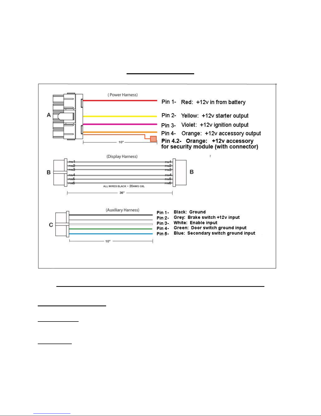
Wire instructions
PLEASE DISCONNECT BATTERY BEFORE INSTALLATION
POWER HARNESS
LARGE RED WIRE: This is the power wire. Connect as directly as possible to the +12v side of the
battery. It supplies power to Touch n Go.
YELLOW WIRE: This is the starter output wire. It provides +12 volts to the starter solenoid during
Page 7

cranking only. A neutral safety switch is required between the yellow output wire and the starter for
safety. This is a switch that will only allow power to flow to the starter solenoid if vehicle transmission
is in park or neutral positions. Alternatively, on a manual, this can be a switch that only allows power
to flow if the clutch is depressed fully.
VIOLET WIRE: This is the ignition output wire. It will supply +12 volts to anything that is connected
to it when the Touch n Go is in ignition on mode (2nd touch, ignition on mode. Teal glow), run mode
(Green glow), and crank mode (Violet glow during cranking). It is important that anything that needs
to stay live during cranking be connected to this wire, such as; electric fuel pump, coil, engine
computer etc. *installer may choose to use relay part # A50 to add a second ignition output that will
turn off during cranking, but will otherwise be on any other time ignition output is activated (during
ignition on mode, and run mode. This is for consumers that user will not want on during accessory mode,
does want on during ignition mode, but does not want on during engine starting (cranking). See wiring
diagram.)*
ORANGE WIRE: This is the accessory output wire. It will supply +12 volts to anything that is
connected to it when Touch n Go is in accessory on mode (1st touch, accessory on mode. Blue glow)
and run mode (Green glow). This output will turn off during cranking. Connections to this wire
typically include radio, power windows, entertainment devices etc. *This allows for use of these devices
without running items unnecessarily such as fuel pump, engine computer and heated oxygen sensors( for
example), that could be damaged when left on for periods of time while engine is not running.*
DISPLAY HARNESS
Alternatively called button harness, this harness is pre-terminated for connection to touch sensitive
button input. It will also be used to connect accessory harnesses to, such as optional L.E.D. harness if
secondary button input is used. If secondary button input is used, touch sensitive button should be
disconnected.
AUXILLARY HARNESS
Black wire: This wire connects to -12 volt chassis ground. A good clean (bare metal) ground
should be made for this wire, free of paint or any other obstruction.
Gray wire: This wire connects to the brake (light) switch. It requites a +12 volt input. Most brake
switches only have two terminals. One terminal has +12 volts supplied to it at all times. The other is
Page 8

connected to the brake light bulbs. If tested with a test light or multi-meter, it will only show +12 volts
when the brake pedal is depressed, sending +12 volts to the brake lights, turning them on. This is the
“open” side of the switch. The gray wire should be connected to this side. When the brakes are
depressed, the Touch n Go unit will get +12 volts via the brake switch. *Some brake switches have
more than two terminals, find the terminals that function as described above. Some brake light
switches only have power when ignition is on. If this is the case, re-wire the “hot” side of the brake light
switch to have +12v at all times.*
White wire: Enable wire. This wire receives a signal from the security system module (when security
is used) to allow access to Touch n Go when proper key fob is detected, and adversely to deny access
when proper key fob is not detected. Disregard blue wire tap. It goes to one of the terminals of the
valet switch (provided with all kits regardless of security option). The other terminal of the valet
switch goes to enable (white) wire of the Touch n Go unit.
Valet switch: Valet switch acts as an override for security. On security optioned kits; leave the switch
on. If the battery in a key fob goes dead, turn valet switch off and Touch n Go will respond to touch
input. On non- security optioned kits, the valet switch can act as a less convenient security option.
Turning the switch on, will arm the system and Touch n Go will not respond to touch inputs. Turning it
off, will enable Touch n Go to operate. It is advisable to mount switch in a hidden location away from
plain sight.
Green wire: This wire connects to the open side of a door pin switch that will provide a -12 volt
ground input. The Touch n go unit has a “retained accessory” output that will keep the accessory wire
activated for up to ten minutes after the engine has been turned off, or until door is opened (a
convenient feature found in many new cars). When he Touch n Go module receives the ground input
it will turn off accessory output wire. The Touch n Go module also uses this wire for other functions
and needs to be connected for proper operation.
Door pin switches usually have one terminal grounded and the other left open when the door is shut.
When the door is opened, the open terminal is connected to ground, turning on dome lights and
providing signals to other components when relevant. In rare cases, door pin switches have +12 volts
instead of ground. This will need to be changed if your car is so equipped!
Blue wire: This wire is a -12 volt ground input wire. This wire is an optional input used only if touch
sensitive button is not used. This wire allows for connection to any normally open monetary switch
Page 9

(such as an engine start switch from a new vehicle) . The same full functionality is retained if this
option is used. Follow instructions for touch button operation. One terminal of the switch should be
connected to ground, and the normally open side of the switch should be connected to the blue wire.
Touch sensitive button should be left unconnected if this wire option is used. An auxiliary L.E.D.
display is available through Phantom - Products that will give same visual light signals for simulated key
positions as touch button.
Toggle switch (valet switch): There is a toggle switch included with your Touch n Go.
When not using security, one leg of the switch should be connected to the white (enable) wire coming
from the Touch n Go unit, and the other leg of the switch should be connected to ground. When using
security, connect the white (enable) wire from the security unit to the opposite side of the switch as the
white (enable) wire from the Touch n Go box. In the event of a dead key fob battery, this switch can
be turned off to de-activate security and allow full use of Touch n Go. The toggle switch can also be
used as a valet switch or simple security measure. If no security is used, the toggle switch must be
turned off (disconnected from ground) in order for Touch n Go to work. Adversely, the toggle switch
can be left on to act as a simpler security measure.
Wiring for security module *where applicable*
POWER HARNESS
Red wire (with 15 amp fuse): This is the +12 volt power wire for the security module. It is pre -
terminated into the Touch n Go power harness.
Black wire: Ground wire. Connect this wire to a clean chassis ground. -12 volts.
Green wire: Lock wire. This wire provides a single negative -12 volt pulse to lock motor. Not
suggested for door solenoid (shaved door handles).
Blue wire: Unlock wire. This wire provides a single negative -12 volt pulse to lock motor. Not
suggested for door solenoid (shaved door handles).
ACCESSORY HARNESS
White wire: Enable wire. This wire connects to the opposite side of the valet toggle switch. Crimp
Page 10

supplied wire terminal to wire, and then connect to one side of the toggle switch.
Red Wire: Accessory wire. This wire connects to the accessory wire on the Touch n Go module via
wiretap. Simply plug into orange wire on Touch n Go harness.
ANTENNA HARNESS
Mount antenna in desired location. The range of the security system will depend on where the
antenna is mounted. The closer to the glass the antenna is placed, the longer the range. The
antenna is a red and black disc connected to a two wire black lead. Even if antenna is located under
center console (for example) it should still have sufficient range.
PLEASE DISCONNECT BATTERY BEFORE INSTALLATION
Warning flash: In the event of a blown fuse, the button will flash red and blue quickly.
The only other condition that will cause this flash is when an over current condition is reached. If this
is the case and no fuse is blown the channel with too much draw will be shut off temporarily.
A rapid red flash happens when there is another type of over-current fault and Touch n Go is in danger
of overheating. It will turn off the effected output channel. The output will re-activate once the
temperature / current draw is within safe limits for at least 30 seconds.
If these conditions occur repeatedly, we recommend the use of a high current bypass relay. In this
case the output channel effected will be used to activate a relay, which can handle the higher load
(20amps or higher continuous.)
Page 11

Page 12

Page 13

Page 14

Page 15

Page 16

Page 17

Further installation notes
Upon installing Touch n Go into some vehicles, certain obstacles could be in place that will complicate
installation. From the late 1980’s to current day, vehicles have become increasingly more complicated.
They implement everything from locking columns to security systems that require coded keys. The
internet provides pretty thorough information on wires, their colors, their function and where they
might be found. This information is usually available and free from third party manufacturer web sites,
such as alarm and remote start manufactures for example. Here are some suggestions for overcoming
these obstacles, and what those obstacles might be.
Newer vehicles:
More than 4 wires exist at the ignition switch: Often times all of the wires still have the same basic
functions as an older ignition switch, and can just be grouped together based on desired operation.
The vehicle manufacturer may have done this for ease of assembly.
Locking steering column: Locking steering columns are managed in two ways: Mechanically, usually
with a spring loaded pin that locks the wheel when the keyed ignition is in off, and electronically with a
motor. You could simply leave the key in the factory ignition, and turn it to the unlock position or
disarm the locking mechanisms. You may even choose to cut the head of the key off so it is less
conspicuous, leaving only the actual shaft part of the key.
Depending on your level of mechanical inclination, you can disarm the mechanical column lock by
removing the pin / locking mechanism. Or you can install a column with no key tumbler in it.
If the car uses an electric motor to lock, it is possible to disarm it also. Check the two wires going to
the motor that activate it. It will use a positive wire and a ground wire, it is possible to independently
hook the wires to ground and a keyed power source, so the column unlocks after the accessory or
ignition power has been turned on. You must observe and maintain the correct polarity that the
vehicles security system uses to activate the motor. It must also be disconnected from whatever
device may be controlling it.
If you are not comfortable doing this, check with a qualified body shop or alarm installation shop as they
need to access these components regularly and may be able to help.
Chip in key: If you have a chip in the key, it may be visible where the exposed metal part of the key is,
Page 18

or it may be contained inside of the plastic portion of the key. Once again, you can leave the key in the
factory ignition. You can also purchase a third party “Factory Security Bypass Module.” These are
available from manufactures of remote start and alarm systems, and can be found at qualified alarm
installation shops or online. They should contain detailed instructions about installation in the
particular vehicle covered and also the quickest route for disarming the factory alarm.
Warranty and Legal
Phantom Products LLC. (“Phantom”) promises to the original purchaser to repair or replace (at
Phantom’s election) with a comparable reconditioned model any Phantom unit (hereafter the “unit”),
excluding without limitation remote transmitters, the associated sensors and accessories, which proves
to be defective in workmanship or material under reasonable use during the first 12 months from the
date of purchase, provided the following conditions are met: the unit was purchased from an authorized
Phantom dealer, the unit was professionally installed and serviced; the unit will be professionally
reinstalled in the vehicle in which it was originally installed; and the unit is returned to Phantom,
shipping prepaid with a legible copy of the invoice or other dated proof of purchase bearing the
following information: consumer’s name, telephone number and address; the authorized dealers name,
telephone number and address; complete product description, including accessories; the year, make
and model of the vehicle and vehicle engine type. All components including without limitation the
controller, remote transmitters and the associated sensors and accessories, carry a one-year warranty
from the date of purchase of the same. ALL PRODUCTS RECEIVED BY PHANTOM FOR WARRANTY REPAIR
WITHOUT PROOF OF PURCHASE WILL BE DENIED. This warranty is non-transferable and is automatically
void if: the original purchaser has not completed the warranty card and mailed it within thirty (30) days
from the date of purchase to the address listed on the card; the unit’s date code or serial number is
defaced, missing or altered; the unit has been modified or used in a manner contrary to its intended
purpose; the unit has been damaged by accident, unreasonable use, neglect, improper service,
installation or other causes not arising out of defects in materials or construction. The warranty does not
cover damage to the unit caused by installation or removal of the unit. Phantom, in its sole discretion,
will determine what constitutes excessive damage and may refuse the return of any unit with excessive
damage.
PHANTOM PRODUCTS, IS NOT OFFERING A GUARANTEE OR INSURANCE AGAINST VANDALISM, DAMAGE
Page 19

OR THEFT OF THE AUTOMOBILE, ITS PARTS OR CONTENTS; AND HEREBY EXPRESSLY DISCLAIMS ANY
LIABILITY WHATSOEVER, INCLUDING WITHOUT LIMITATION, LIABILITY FOR THEFT, DAMAGE AND/OR
VANDALISM. THIS © 2010 Phantom Products, LLC. All rights reserved.
WARRANTY DOES NOT COVER LABOR COSTS FOR MAINTENANCE, REMOVAL OR REINSTALLATION OF
THE UNIT OR ANY CONSEQUENTIAL DAMAGES OF ANY KIND. IN THE EVENT OF A CLAIM OR A DISPUTE
INVOLVING PHANTOM OR ITS SUBSIDIARY, THE VENUE SHALL BE LAWRENCE COUNTY IN THE STATE OF
ILLINOIS. ILLINOIS STATE LAWS AND APPLICABLE FEDERAL LAWS SHALL APPLY AND GOVERN THE
DISPUTE. THE MAXIMUM RECOVERY UNDER ANY CLAIM AGAINST PHANTOM SHALL BE STRICTLY
LIMITED TO THE AUTHORIZED PHANTOM DEALER’S PURCHASE PRICE OF THE UNIT. PHANTOM SHALL
NOT BE RESPONSIBLE FOR ANY DAMAGES WHATSOEVER, INCLUDING BUT NOT LIMITED TO, ANY
CONSEQUENTIAL DAMAGES, INCIDENTAL DAMAGES, DAMAGE TO VEHICLE, DAMAGES FOR THE LOSS OF
TIME, LOSS OF EARNINGS, COMMERCIAL LOSS, LOSS OF ECONOMIC OPPORTUNITY AND THE LIKE. NOT
WITHSTANDING THE ABOVE, THE MANUFACTURER DOES OFFER A LIMITED WARRANTY TO REPLACE OR
REPAIR THE CONTROL MODULE SUBJECT TO THE CONDITIONS AS DESCRIBED HEREIN. THIS WARRANTY
IS VOID IF THE UNIT HAS NOT BEEN PURCHASED FROM PHANTOM, OR AN AUTHORIZED PHANTOM
DEALER, OR IF THE UNIT HAS BEEN DAMAGED BY ACCIDENT, UNREASONABLE USE, NEGLIGENCE, ACTS
OF GOD, NEGLECT, IMPROPER SERVICE, OR OTHER CAUSES NOT ARISING OUT OF DEFECT IN MATERIALS
OR CONSTRUCTION. Some states do not allow limitations on how long an implied warranty will last or
the exclusion or limitation of incidental or consequential damages. This warranty gives you specific legal
rights and you may also have other rights that vary from State to State. This warranty is only valid for
sale of product(s) within the United States of America. Product(s) sold outside of the United States of
America are sold “AS-IS” and shall have NO WARRANTY, express or implied.
 Loading...