

Page 1
PHANTOM
Miro® LAB / LC / R
High-Speed Cameras
MANUAL
When it’s too fast to see, and too important not to.
Miro® LAB, LC, R GETTING STARTED MANUAL ZDOC-64078-MA-0021 Rev 1
®
Page 2

w w w . v i s i o n r e s e a r c h . c o m
Phantom Miro LAB / LC / R Series Camera Manual
PN: ZDOC-64078-MA-0021 Rev 1
Last Updated: 15-DEC-2015
Page 3

when it’s too fast to see, and too important not to.
Phantom Miro
LAB / LC / R Series
MANUAL
®
100 Dey Road
Wayne, NJ 07470 USA
+1.973.696.4500
phantom@visionresearch.com
www.highspeedcameras.com
www.visionresearch.com
Page 4

w w w . v i s i o n r e s e a r c h . c o m
Written and produced by the Marketing Department at Vision Research.
The contents of this manual are subject to change without notification.
PN: ZDOC-64078-MA-0021Rev 1
Last Updated: 15-DEC-2015
Page 5

Contents
Introduction
1
Quick Start Guides
2
Phantom Software
3
Miro LC Touch Screen Interface
4
Download & Image Processing
5
Measurements
6
CineFlash & CineFlash Dock
7
Accessories
8
Support
9
1
13
21
35
53
57
67
71
77
Phantom Miro LAB / LC / R Series Camera Manual
Page 6

Performance
Levels and Key
Specifications
Max. Resolution
Sensor Mpx
Max. FPS at
Max. Resolution
Throughput
Sensor Size
Pixel Pitch
CAR
Min. Exposure
features
Straddle Time
Native ISO
(12232 SAT
Method)
Memory
Trigger Options
Ethernet
Video Out
Special
Features
LAB110
LC110
R111
1600 fps 3200 fps 1850 fps 730 fps 1380 fps 410 fps 800 fps
Gpx/s
25.6mm x 16.0mm
Dedicated BNC, via capture port, Image-Based Auto-Trigger, Phantom PCC software,
LAB310
LC310
LAB3a10
R311
1280 x 800 1280 x 1280 1920 x 1200 2560 x 1600
1Mpx 1.6Mpx 2.3Mpx 4Mpx
1.6
20 μm 10μm
2 μs 1 μs
500 ns 1.4 μs 500 ns 1.4 μs
16,000 T Mono
2,000 T Color
6,400 D Mono
2,000 D Color
Not all camera models support video output. And, the RCU is not supported on models
Partition memory into segments and make shorter recordings back-to-back without
missing any action (63 maximum), Burst mode, Shutter off mode for PIV exposure,
3.2 Gpx/s 1.6 Gpx/s 3.2 Gpx/s 1.6 Gpx/s 3.2 Gpx/s
12.8mm x
12.8mm
64 x 8 increments (Continuous Adjustable Resolution)
1
1
1
6GB, 12GB high-speed internal RAM
CineFlash non-volatile memory storage (120GB or 240GB w/Dock)
or On-Camera Controls
Standard Gb Ethernet for control and data
without video output (see Video System table on a page 5)
Continuous recording, Extreme Dynamic Range (EDR)
Power
LAB120
LC120
R121
19.2mm x 10.8mm 25.6mm x 16mm
12 - 28 VDC, 65 W
LAB320
LC320S
R321S
12,500 T Mono
1,600 T Color
5,000 D Mono
1,250 D Color
LAB140
R141
1
1
1
LAB340
R341
Key
Specification
Based on
LAB-Series LC-Series
Body Style
Battery Power
Internal
Mechanical
Shutter
1
Measured using the ISO 12232 SAT method 2 Option to remove for higher-shock applications
Phantom Miro LAB / LC / R Series Camera Manual
Standard Standard Standard
None
Sony BP-U30 or
BP-U60 rechargeable,
external charger
required
R-Series
Rxx1 -Series Rxx0 -Series
Sony BP-U30 or
BP-U60 rechargeable,
external charger
required
2
Sony BP-U30 only,
rechargeable, external
charger required
Optional, if equipped
shock rating limited to
40G maximum
Page 7
1
Introduction
Introduction
Body Style LAB-Series LC-Series R-Series
Miro 11x
Miro 31x
Miro 3a1x
Miro 12x
Miro 32x
Miro 32xS
Miro 14x
Miro 34x
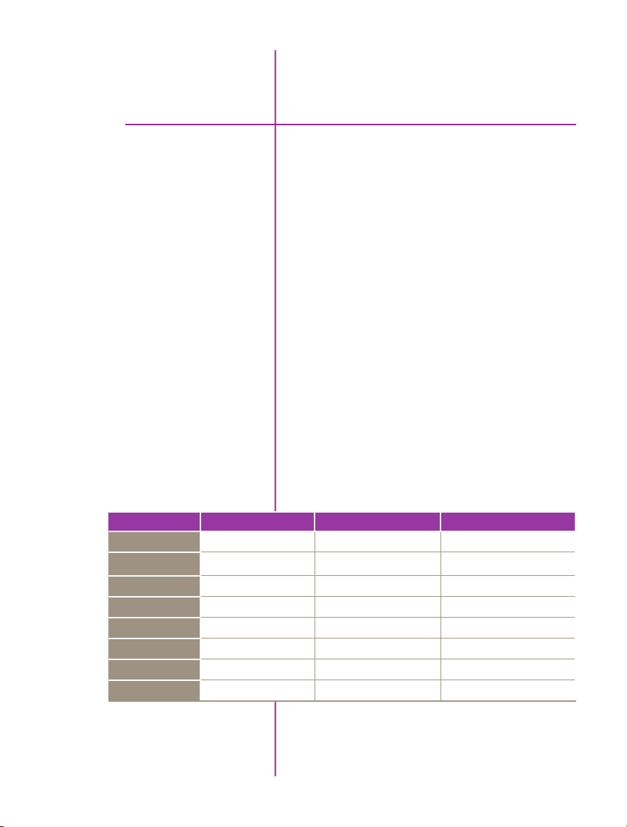
Phantom Miro cameras come in a variety of models and a
range of performance levels. There are three-body styles.
The LAB-Series is designed for laboratory / officeenvironment applications where computer control is
preferred – for example, a fixed installation where highspeed Cines are immediately saved on a computer for
viewing and analysis.
The LC-Series has an integrated flip out LCD touch screen
for on-camera control and viewing of recorded cines. It is
best employed where the camera will be used in a variety
of applications, often requiring portability.
The R-Series is also designed for applications where
computer control is used, and is packaged in a robust,
shock-tolerant, all-metal body for applications in outdoor
and harsh environments.
Not all performance levels are available in all body styles.
Below is a table showing what is available.
√ √ √
√ √ √
√
√ √ √
√
√ √
√ √
√ √
Chapter 1: Introduction
1
Page 8

Camera Capabilities
The LAB310, LAB110, LC310, LC110, R311, and R111
cameras are capable of capturing 1 Giga-pixels per
second (Gpx/s) of data from our proprietary CMOS sensor.
At full resolution (1280 x 800), the LAB310, LC310, and
R311 can capture at 3,200 frames-per-second (fps); the
LAB110, LC110 and R111 can capture at 1,600 fps.
The LAB3a10, LAB320, LAB340, LC320S, R341, and
R321S, feature 3.2 Gpx/s throughput. The maximum
frame rate of 1,850 fps at full resolution (1280 x 1280)
can be achieved by the LAB3a10. The LAB320, LC320S,
and R321S support a maximum frame rate of 1,380 fps
at full resolution (1920x1200). And the LAB340, and
R341 can record at a maximum frame rate of 800 fps full
resolution (2560x1600)
The LAB120, LC120, and R121S, achieve 1.6 Gpx/s
throughput, as do the LAB140, and R141. The LAB120,
LC120, and R121 maximum frame rates are 730 fps at
full resolution (1920 x 1200) while the maximum frame
rate of the LAB140, and R141 is 410 fps at full resolution
(2560x1600)
Image Storage
2
Phantom Miro LAB / LC / R Series Camera Manual
High throughput is important. At any given resolution,
a camera with the highest throughput will provide the
fastest possible frame rates.
The Phantom Miro LAB / LC / R Series cameras can be
equipped with 6GB, or 12GB of high-speed memory.
Cameras with 12GB of memory, recording at 1,000 fps
can record a single high-speed shot (called a Cine) for
almost 2.7 seconds.
The Phantom Miro LAB / LC / R Series cameras are also
compatible with Phantom CineFlash long recording devices available in 120GB and 240GB capacities.
The Phantom Miro LAB / LC / R Series cameras can
securely save to an attached Phantom CineFlash specially
designed for high throughput, which translates into save
and retrieval times far better than what you get with
commercial solutions designed for slow-speed cameras.
The ability to save data at rates up to 70MB per second
translates into less downtime due to long file save times
and higher camera productivity.
Page 9
Sensor Characteristics
The Phantom Miro LAB / LC / R Series use a proprietary
CMOS sensor designed by Vision Research and are
available in monochrome or color versions.
The sensor resolution / shape of the allows the user
to keep moving objects within the frame longer and is
compatible in the aspect ratio with modern display
technology. The physical sizes of the sensors are listed
in the table below.
Phantom Camera Model
Miro LAB340 / R340
Miro LAB140 / R140
Miro LAB320 / LC320S / R320S
Miro LAB120 / LC120 / R121
Miro LAB 3a10
Miro LAB310 / LC310 / R311
Miro LAB110 / LC110 / R111
Resolution.
(Width x Height
in pixels)
2560 x 1600 10 μm 25.60 x 16.00 30.19
2560 x 1600 10 μm 25.60 x 16.00 30.19
1900 x 1200 10 μm 19.20 x 12.00 22.64
1900 x 1200 10 μm 19.20 x 12.00 22.64
1280 x 1280 10 μm 12.80 x 12.80 18.10
1280 x 800 20 μm 25.60 x 16.00 30.19
1280 x 800 20 μm 25.60 x 16.00 30.19
Pixel Size
(µm)
Size
(Width x Height
in mm)
Size
(Diagonal
in mm)
The 10 micron (μm) pixels of the LAB340, R340, LAB140,
R140, LAB320, LC320S, R320S, LAB120, LC120, R121,
and LAB3a10 result in a light sensitivity of ISO 5,000D1
and 12,500T for monochrome cameras, and color
cameras 1,250 D1 and 1,600T1.
The 20 micron (μm) pixels result in high light sensitivity.
The LAB310, LC310, R311, LAB110, LC110 and R111
cameras have a sensitivity of ISO 6,400D1 and 16,000T
for monochrome cameras, and color cameras 2,000 D1
and 2,000T1.
All Phantom Miro Series cameras have global electronic
shutters, with minimum exposure times of 1μs for the
LAB340, R340, LAB140, R140, LAB320, LC320S, R320S,
LAB120, LC120, R121, and LAB3a10 cameras; 2μs for
the LAB310, LC310, R311, LAB110, LC110 and R111
models.
1
Measured using the ISO 12232 SAT method
Chapter 1: Introduction
3
Page 10
Command and Control
Phantom Miro cameras are easy to set up and control.
Use our Phantom Camera Control (PCC) software over
a Gb Ethernet connection, a hand-held Phantom RCU, or
the on-board LCD touch screen (on the LC-Series only)
to access and control the camera’s features. (An SDK
enabling custom software interfaces and LabView drivers
are also popular ways to set up and control Phantom
cameras.)
Detailed information about Phantom cameras,
features, and software can be found at:
www.visionresearch.com
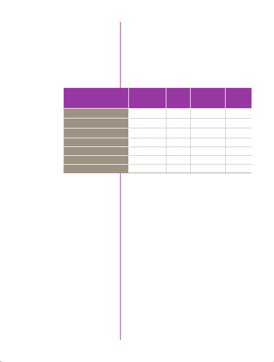
Video Out
Not all camera models support video output. And, the RCU
is not supported on models without video output.
The Video System table below shows what video system is
available on each model.
Body Style LAB-Series LC-Series R-Series
Miro 11x
Miro 31x
Miro 3a1x
Miro 12x
Miro 32x
Miro 32xS
Miro 14x
Miro 34x
Advanced Features
None NTSC / PAL NTSC / PAL
None NTSC / PAL NTSC / PAL
None – –
None NTSC / PAL NTSC / PAL
None – –
– HD-SDI HD-SDI
None – None
None – None
Image-Based Auto-Trigger (IBAT): Phantom Miro LAB
/ LC / R Series cameras can detect changes an image
which can be used to trigger the camera (or even a
number of cameras), making it easy to record
unpredictable events.
Multi-Cine: The internal memory of a Phantom Miro LAB
/ LC / R Series camera can be partitioned into as many as
63 segments for shorter recordings, back-to-back, without
missing any action.
4
Phantom Miro LAB / LC / R Series Camera Manual
Burst Mode: Precisely generate a programmable
number of frames for every (internal or external) frame
synchronization pulse.
Page 11

Internal Mechanical Shutter: Easily perform black
references remotely using the built-in mechanical capping
shutter for optimum image quality.
Continuous Recording: Automatically save cines from
internal camera memory to an external storage, without
user intervention.
Extreme Dynamic Range (EDR): Vision Research’s
unique Extreme Dynamic Range (EDR) feature is standard
on all Phantom Miro LAB / LC / R models. With EDR enabled, each pixel in a frame will receive one of two exposure times – a short exposure for potentially over-exposed
pixels and a longer exposure for pixels receiving normal
light levels. This provides detail in areas of the image that
would otherwise be overexposed. EDR is usually recommended for monochrome cameras only.
Lensing
Shutter Off: The Shutter Off mode was designed for
PIV applications, and maintains a maximum exposure
regardless of frame rate. This allows for a straddle time of
500 ns for the LAB, 310LAB120, LAB110, LC310, LC120,
LC110, R311, R121, R111 cameras, and 1.4 μs on the
LAB340, LAB320, LAB3a10, LAB140, LC320S, LC120,
R341, R321S, R141, R121 cameras.
Phantom Miro LAB / LC / R Series cameras are available
with 4 different interchangeable lens mounts, which must
be chosen at the time of purchase.
Choose between a Canon EOS, Nikon F-mount, 1"
C-mount, or 35mm PL-mount.
The EOS mount enables the use of compatible EF and
EF-S lenses, and focus and aperture can be adjusted via
our Phantom Remote Control Unit (RCU), Phantom Camera
Control software (PCC), or using an adjustment ring on
the lens mount. Remote control of focus and aperture is a
huge benefit when cameras are remotely located and/or
difficult to reach.
The Nikon F-mount support F & G style lenses.
A Nikon F mount adapter allows the use of F-mount lenses
on EOS mount.
Chapter 1: Introduction
5
Page 12
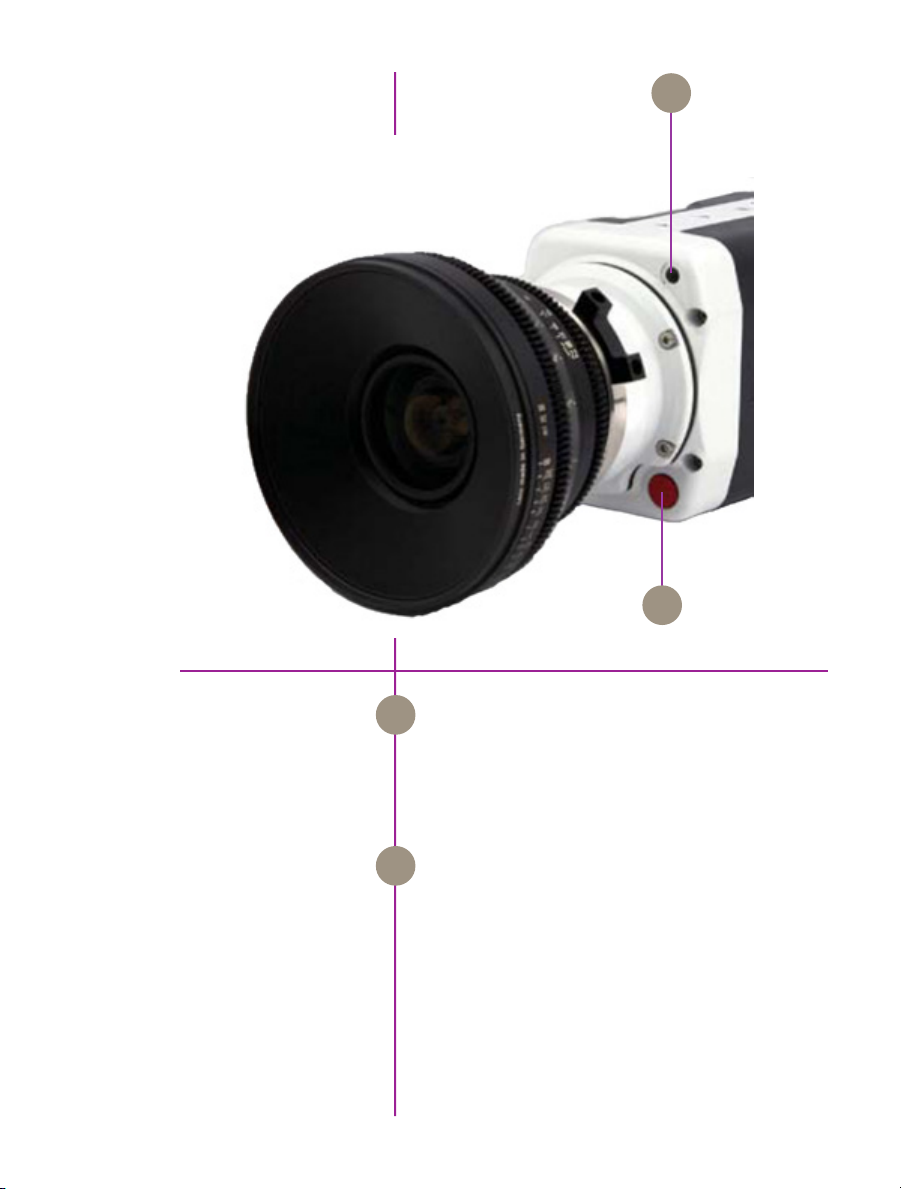
A
B
Autoset
Autoset
on-camera controls
6
Phantom Miro LAB / LC / R Series Camera Manual
Tap to scroll through video tool functions:
A
Zoom (1:1), Threshold and Live mode
Long press (3 seconds) will perform an internal CSR
(current session reference)
Press once to trigger the camera
B
Long press (5 seconds) will delete the last RAM Cine
file and re-arm the camera.
Page 13
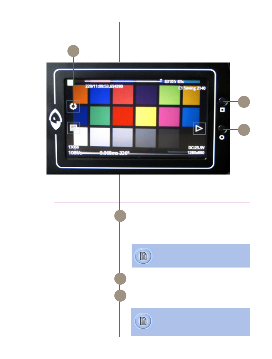
C
A
B
Image shown is of the LCD screen flipped around and folded back
Menu
lcd panel controls
OSD Display
Menu
Turns on / off ‘Menu’ icons. Exiting the menu is an
A
electronic reset of the touch screen. Reset takes about
5 seconds. Double-clicking the square button also
resets the screen.
Mount camera onto suitable support.
Attach and adjust appropriate lens.
Turns on/off all on-screen displays.
B
Displays the main ‘capture and setting’ control
C
interface.
See ‘Chapter 3: Miro LC Touch Screens’ for a
brief description of the various ‘Menu’ screens.
into the side of the camera
7
Chapter 1: Introduction
Page 14
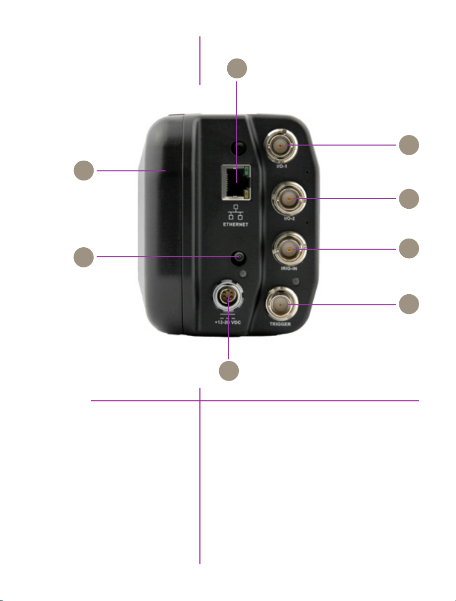
B
C
A
D
H
G
Camera models supported with this body style are the
Phantom Miro 11x, Miro 31x, Miro 3a1x, Miro 12x,
Miro 32x, Miro 32xS, Miro 14x, and Miro 34x.
LAB Series Body Style
E
F
rear connector panel
8
Phantom Miro LAB / LC / R Series Camera Manual
Page 15

CineFlash Compartment Door
Phantom CineFlash access door.
A
1Gb Ethernet
I/O-1
I/O 2
IRIG-In
RJ45 CAT5 (for control and data transfer)
B
F-Sync / Event / Strobe / Memgate (Aux1) selectable:
C
- F-Sync / +5V maximum threshold, input is
also compatible with TTL levels and must be
properly terminated, (50-ohms).
- Event / active-low isolated input marks events
during recording; signal must be active when
the strobe is high.
- Strobe / isolated collector output with 1k
pull-up, active during frame exposure.
- MemGate / active-low isolated input,
temporarily stops image acquisition during
recording.
Ready / Strobe / selectable:
D
- Ready / isolated collector output with 1k
pull-up, indicates camera is ready for trigger.
- Strobe / see description (C) above.
Unmodulated IRIG-B timecode format input. Input
E
withstands signals of up to +/- 15v. The input threshold
is 1.5V, compatible with TTL levels.
Trigger
+12-28 VDC
Battery Reset Switch
Isolated input; active low. Can be activated by a switch
F
to ground. Pulse must be 3μs long minimum.
+12-28 Volts DC standard Miro power.
G
Forces battery power off. When activated any Cine
H
stored in camera RAM will be purged.
9
Chapter 1: Introduction
Page 16

B
C
D
E
A
F
H
G
Camera models supported with this body style are the
Phantom Miro 11x, Miro 31x, Miro 12x, and Miro 32xS,
Miro 14x, and Miro 34x.
LAB Series Body Style
10
Phantom Miro LAB / LC / R Series Camera Manual
Page 17

CineFlash Compartment Door
Phantom CineFlash access door.
A
Battery Status Button
1Gb Ethernet
Capture
Power
Off / Auto / On Switch
F-Sync
Provides status of battery charge.
B
RJ45 CAT5 (for control and data transfer)
C
Provides I/O signaling via attached capture cable
D
(signals) or Miro Break-Out Box (signals).
+12-28 Volts DC standard Miro power.
E
Determines camera powering options:
F
- Off / camera off (no power applied to a
camera).
- Auto / requires DC input to power up camera
(battery, if connected and charged, maintains
power if Cine is stored in RAM and DC power
loss only).
- On / camera immediately runs with DC or
battery input power is applied.
F-Sync / +5V maximum threshold, input is also
G
compatible with TTL levels and must be properly
terminated, (50-ohms).
Trigger
Trigger / Isolated input; active low. Can be activate by a
H
switch to ground. Pulse must be 3μs long minimum.
11
Chapter 1: Introduction
Page 18

12
Phantom Miro LAB / LC / R Series Camera Manual
Page 19

2
Quick Start Guides
Prepare Your Computer
Install PCC Software
Connect the Camera to
the Computer
via pcc software
Camera controlling computers:
1. Must have either the Microsoft Windows XP Pro,
VISTA Business Edition, Windows 7 or Windows
8.1 operating system installed.
2. Firewalls must be turned off.
(Contact your IT Group if necessary)
3. Using the ‘Windows Control Panel’ set the IP
address of your computer’s network card to
100.100.100.1 with a 255.255.0.0 subnet mask.
Install the latest version of Phantom Camera Control (PCC)
software from the accompanying CD or USB key.
Connect the 12-28 VDC power supply to the camera’s
Power Input connector.
Attach the supplied Ethernet cable between the Phantom
camera and the computer.
Connect the supplied Capture cable to the Phantom
camera.
If an external trigger is being used to trigger the camera,
connect it to Trigger connector on the rear panel of the
camera.
Attach Phantom CineFlash
Select Camera for Use
Mount a Phantom CineFlash, if available.
Detailed information about attaching a Phantom
CineFlash can be found in Chapter 7: Phantom
CineFlash & CineFlash Dock of this manual.
In the ‘Manager’ tab double-click on the Phantom camera
to be used from the ‘Cameras’ group folder.
13
Chapter 2: Quick Start Guides
Page 20
Define Recording Parameters
Click the ‘Live’ tab.
Click ‘Cine Settings’ and define following parameters by
either the selecting the required value from the pull-down
selection list, or type a value into the respective data entry
field.
1. Set ‘Resolution’ to the required Width x Height.
2. Choose the required ‘Sample Rate’ and ‘Exposure
Time’.
3. Ensure the EDR, (Extreme Dynamic Range)
exposure time is set to zero (0).
4. Post Trigger to zero (0) by:
a. Moving the ‘T’ (Trigger Position) slider to the
right, or
b. Enter zero (0) into the ‘Last’ data entry field.
Click on the CSR button to perform a Current Session
Reference.
‘Arm’ Camera
Trigger
Edit Cine
14
Phantom Miro LAB / LC / R Series Camera Manual
Click the ‘Capture’ button to start recording to the camera’s internal memory (circular buffer).
At the end of the action, click the action ‘Trigger’ button
on the bottom of the ‘Live’ panel, or
Provide a switch closure or an external trigger signal
(TTL pulse) via the Trigger connector.
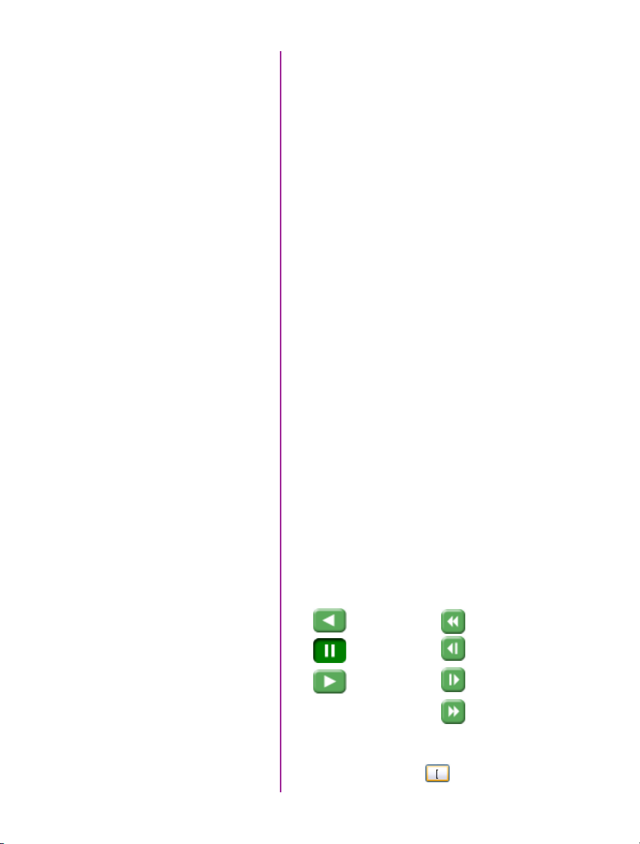
Click the ‘Play’ tab.
Using the following Video Control Buttons to locate the first
image of the cine to be saved.
Rewind
Pause
Play
Locate the first image of the cine to be saved.
Click the ‘Mark-In button.
Fast Rewind
Rewind 1 Frame
Advance 1 Frame
Fast Forward
Page 21
Locate the last image of the cine to be saved.
Click the ‘Mark-Out’ button.
Select ‘Play, Speed, & Options” and enable (check) ‘Limit
to Range’.
Under the Video Control Buttons, click the ‘Jump to Start’
button.
Review Edited Cine
Save to Computer
Save to Attached
Phantom CineFlash
Review the edited cine using the Video Control Buttons.
Click the ‘Save Cine...’ button on the bottom of the ‘Play’
panel.
In the ‘Save Cine’ window:
1. Navigate to the folder where you want to save the
cine file.
2. Enter a file name for the cine file in the ‘File name:’
data entry field.
3. From the Save as type pull-down selection list,
select the ‘Cine Raw, *.cine’ file format.
4. Click the Save button to begin downloading the
cine file from the camera to the computer’s hard
drive.
Click the down-arrow of the ‘Save Cine... button.
Select ‘Save RAM Cine to Flash’ (in popup window).
Click the Save button to save the cine file onto the Phantom CineFlash.
Confirm cine save before deleting from
internal memory
Confirm Computer Save
Click the ‘Open File’ button.
In the ‘Open Cine’ window:
Navigate to the folder containing the saved cine file.
Highlight the cine file to be opened.
Click the Open button.
15
Chapter 2: Quick Start Guides
Page 22

Confirm CineFlash Save
Using the Video Control Buttons, review the saved cine file.
Click the ‘Manager’ tab.
Double-click on the ‘Cine F#’ file under the camera used
to record the cine.
Using the Video Control Buttons, review the saved cine file.
16
Phantom Miro LAB / LC / R Series Camera Manual
Page 23

Mount camera onto suitable support.
Attach and adjust appropriate lens.
Power Up Camera
Setup Video Monitor
Attach Phantom CineFlash
Set Recording Parameters
Connect a suitable power supply (12-28VDC) to the Power
Input connector, then set the power switch to the ‘ON’
position, or insert battery.
Connect a suitable HD-SDI video monitor (not supplied)
to the ‘HD-SDI’ connector on the connector panel of the
camera.
Mount a Phantom CineFlash, if available. For detailed
instruction see Chapter 7: Phantom CineFlash & CineFlash
Dock IV.
Click the ‘Menu’ button (square) to display touch screen
menu.
Tap the ‘Menu’ icon as to bring up the main capture and
setting control interface.
• Set ‘Resolution’ to the required width x height
• Choose the required ‘Speed’ (frame rate) and
‘Exposure Time’ (shutter)
• Set the ‘Post Trigger’ (trigger position) at the
beginning, or the end, or some position within
the internal memory.
Scroll up and down for desired setting. Tap once to select
parameter to change.
Perform Black Reference
Perform White Balance
(Color Cameras Only)
Press (3 seconds) the ‘Autoset’ button (front of the
camera) to perform an internal CSR (Current Session
Reference).
Black Reference should be performed after all
recording parameters have been set.
Tap on ‘AWB’ (Automatic White Balance) icon (upper right).
Place a white or neutral non-saturated object in the center
square and tap once.
via miro lc touchscreen
17
Chapter 2: Quick Start Guides
Page 24
‘Arm’ Camera
Trigger
Edit Cine
Press the ‘Trigger’ button (front of camera) for 5 seconds
to switch from ‘Pre-trigger’ or ‘Cine Stored’ to ‘Waiting for
Trigger’ (‘Loop’ mode).
Tap the ‘T’ (Trigger) icon (right-side) or Press the ‘Trigger’
button (front of camera).
Tap the play icon in the ‘Cine Stored’ screen.
Tap ‘Forward’ or ‘Reverse’ icons to play RAM cine
(multiple times to speed up playback).
Tap ‘Pause’ icon to stop playback.
Locate the first image to be saved and select ‘Mark-In’
icon.
Locate the last image to be saved and tap the ‘the
Mark-Out’ icon.
Review the edited Cine.
Apply a long press over the Mark-In and/
or Mark-Out icons to reset Cine file start/end
points respectively.
Save to CineFlash
Verify Save to CineFlash
(optional)
‘Re-Arm’ Camera
18
Phantom Miro LAB / LC / R Series Camera Manual
‘Save’ marked frames to Phantom CineFlash.
Tap the ‘file management’ icon on the LCD menu,
and then tap on the ‘CF’ (CineFlash) icon to bring up
the CF menu. This will show the entire list of files on the
CineFlash drive. Ensure the last shot is there by checking
the time and file size.
Files stored within the CineFlash cannot be played
back on the LCD menu or over video. They can,
however, be viewed in Phantom PCC software.
From the LCD menu, tap on the File Management icon.
The RAM Cine and status will be visible. Tap on the RAM
Cine and then tap the X to delete. Tap the Record icon to
start the camera in capture.
If there is an asterisk* next to the RAM file that
means it has not been saved to the CineFlash.
Alternatively, a long press (5 seconds) on the front camera
trigger button will also delete the last RAM Cine and put
the camera back in Capture mode.
Page 25

‘Connect Camera to
Remote Control Unit
Connect an HD (BNC) cable between the ‘Video-In’
connector on the rear of the Remote Control Unit (RCU),
and the HD-SDI connector on the rear panel of the
camera.
Connect the Remote cable (9-pin female) to the ‘Remote’
connector on the rear of the RCU.
Connect the Remote cable (9-pin male) to the ‘Remote’
connector on the camera’s rear panel.
Power Up Camera
Power Up RCU
Install Phantom CineMag IV
Set Recording Parameters
Connect a suitable power supply (20-28VDC) to the Power
Input connector, then set the power switch to the ‘ON’
position.
Hold in the RCU ‘Menu’ button (2 seconds).
Insert a Phantom CineFlash, if available. For detailed
instruction see Chapter 7: Phantom CineFlash & CineFlash
Dock.
Gently depress the ‘Setup’ button, then the Acq,
(Acquisition), button.
Set the‘Aspect Ratio’: Press the down-arrow (right of
‘Aspect Ratio’ field) and select an ‘Aspect Ratio’ from the
pull-down selection list.
Define the Resolution, Frame Rate, Exposure, and Post
Trigger settings using the Numerical Keypad to specify the
desired setting.
1. To overwrite the present value:
2. Tap the entry field once, (turns entry field yellow),
then
3. Tap the key pad to enter the desired value.
4. Tap the Enter key to set the value.
To append the value:
1. Tap the entry field twice, (turns entry field white),
then
2. Tap the key pad to append the value.
via remote control unit
3. Tap the Enter key to set the value.
19
Chapter 2: Quick Start Guides
Page 26
Press the Return, , icon (upper-left) to return to the
Setup Screen.
Perform CSR
Perform White Balance
(Color Cameras Only)
‘Arm’ Camera
Trigger
Edit Cine
Press the ‘Capture’ button.
Tap the CSR, (Current Session Reference), button
When prompted tap the Begin button.
Tap the ‘White Balance’ button.
Place a white or neutral non-saturated object in front of
the camera.
When prompted tap the Begin button.
Press the Rec, (Record), button.
Apply a trigger to the camera by depressing the hardware
Trigger’ button (on RCU), or apply ‘Trigger-In’ (TTL pulse)
signal to the Trigger connector on the back of the camera.
Click the Play button.
Locate the first / last image to be saved by:
Performing a Quick Search:
Rotate the Jog/Scroll dial until desired point in cine is
achieved, or
Press and hold down on ‘Image Location Identifier’
arrow, , located just below the Cine Editor Bar and
slide finger right to quickly advance cine, slide left to
quickly rewind (present image number is displayed
above).
Save to CineMag
20
Phantom Miro LAB / LC / R Series Camera Manual
Using Video Control buttons:
Play
Reverse
Pause
Click the Mark-In and Mark-Out buttons to set
the first / last images, respectively, of the cine to be saved.
Tap the ‘Save’ button to save the edited RAM cine file to
the Phantom CineMag.
Page 27

3
Phantom Software
The latest version of Phantom PCC software
can be found and downloaded from the support
section of the Vision Research website:
www.visionresearch.com
Pre-Installation
PCC (Phantom Camera Control)
Application Overview
Toolbar
Phantom control software is certified to operate with the
following Microsoft Windows operating systems: Windows
XP Pro, Windows VISTA Business Edition, Windows 7 and 8.
The computer and camera must be associated with the
same sub-network to communicate with one another.
Vision Research has preset IP address (100.100.x.x) with
a subnet mask (255.255.0.0) to the camera. Typically, the
IP address 100.100.100.1 / 255.255.0.0 is defined to the
control computer. When multiple computers are used to
control the same camera, each computer requires a unique
IP address, for example, 100.100.100.1 (255.255.0.0),
100.100.100.2 (255.255.0.0), and so on.
The software is built around a multi-layered work area that
includes the following work areas:
Provides quick access to the most frequently used
functions. Position the mouse over a button and wait for a
second to display a text box describing what it is.
Note the ‘Help’ buttons which provide valuable
reference information about the software, including
extensive documentation.
Chapter 3: Phantom Software
21
Page 28
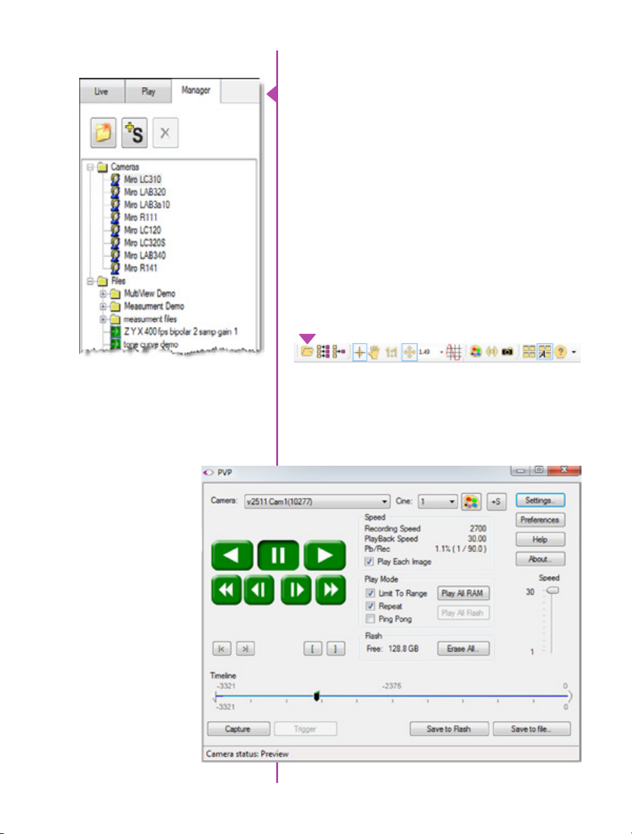
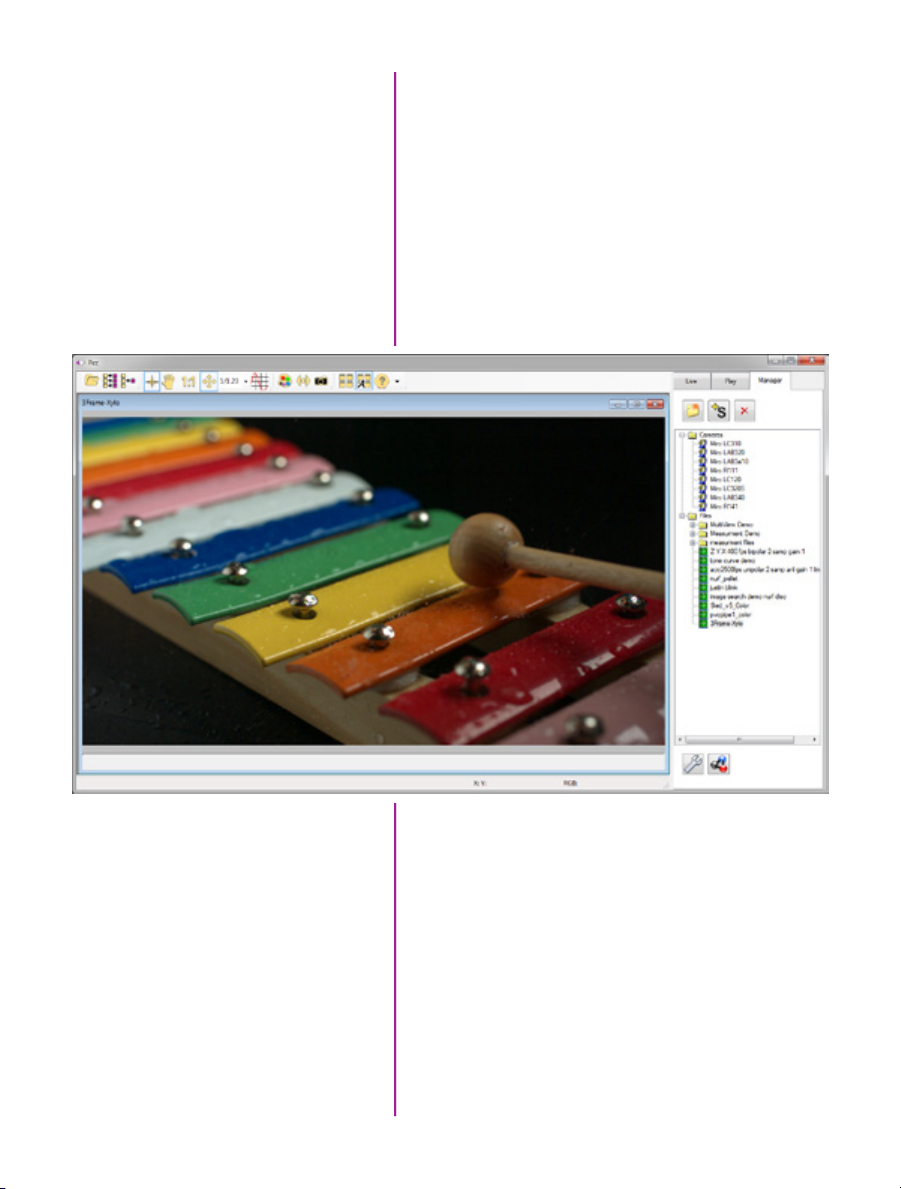
Control Tabs
The main window of PCC is divided into three tabs: Live,
Play and Manager.
When first started, the ‘Manager’ tab is selected. It is in
this tab connected cameras are displayed, selected for
use, and renamed. It is also used to manage saved Cine
files.
To rename, highlight then click the name of a camera.
This can be useful when working with multiple cameras.
All camera control and setting of shooting parameters
(frame rate, shutter, etc.) are performed in the ‘Live’ tab.
The ‘Play’ tab is used to review, edit, and save Cine files,
(either from the camera or from files on the local hard
drive).
PVP (Phantom Video Player)
Application Overview
22
Phantom Miro LAB / LC / R Series Camera Manual
PVP can be launched directly from the desktop, or
by clicking the ‘Video Out’ toolbar button in PCC. PVP
controls only the camera’s HD-SDI outputs as connected
to a compatible SDI monitor.
Page 29
PVP, provides the ability to view, capture, review, edit, and/
or save a Cine recorded into the camera’s RAM to a hard
drive, or installed Phantom CineMag IV. PVP is extremely
effective when used with the high-resolution cameras
since most computers are not powerful enough to view
the live or captured raw files smoothly.
The camera’s video mode and display settings are also
pcc software
set through PVP. Video systems will vary based on the
country you are in, what kind of video monitor used, and
the required display resolution. All available video setting
for the connected camera can be found in the ‘Settings’
menu of PVP.
Camera Control via PCC
PCC provides the ability to select various units for specific
camera parameters by clicking the ‘Preference’ button at
the bottom Manager tab.
Units can be set to commonly used values (‘Presets’)
or they can be customized using the pull-down
selection lists. First-time users should use one of
the three ‘Presets’.
23
Chapter 3: Phantom Software
Page 30
The ‘Exp’ unit is probably the most important unit to be
set. It specifies what unit to use when setting the exposure
time. You probably will want this set to micro-seconds. The
other unit to set is PTF (Post Trigger Frames) covered later
in this section. Every Phantom Ultrahigh-speed cameras
support EDR (Extreme Dynamic Range) exposure.
Selecting a Camera
Double-click the camera(s) to be controlled listed in the
‘Manager’ tab, or select the camera(s) from the ‘Camera’
pull-down list in the ‘Live’ tab.
Image Processing
24
Phantom Miro LAB / LC / R Series Camera Manual
Once a camera is selected a ‘Preview’ panel will display
to the left of the control tabs showing the current image
being captured by the camera. This image may differ
slightly to that of the image being output over the
camera’s two HD-SDI ports due to display differences
in the video monitor and computer screens.
Page 31
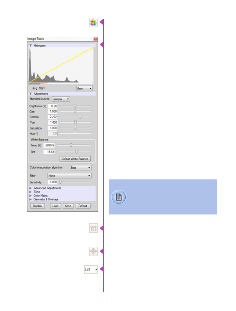
You can adjust the display options by clicking on the
‘Image Tools’ toolbar button.
The ‘Image Tools’ window is used to view a ‘Histogram’
and change settings that affect the computer display and
the video output from the camera.
Some of the variables include; brightness, gain, gamma,
saturation, hue, white balance adjustments (Temp (K) and
Tint), individual red, green and blue pedestal, gain and
gamma values, tone control, and more.
When Log mode is selected, most of these variables are
locked and cannot be adjusted.
At the bottom of the window is a ‘Default’ button that
restores all parameters except white balance, tone, and
color matrix to their default values.
The ‘Default White Balance’ button restores white balance
to the default (which under the most typical lighting will
produce a green image).
The Tone ‘Reset’ button restores the image tone to the
default values, and the Color Matrix ‘Restore’ button return
the color matrix values to their default values.
Changes made only affect the meta data of the
Cine file, not the raw data. If you are recording
the camera’s video output it is important that
these be set to values that produce the image
you wish to record.
The ‘Zoom Actual Size’ toolbar button resizes the images
being displayed in the Preview/Playback panel to their
actual size.
The ‘Zoom Fit’ toolbar button resizes the images to fit
panel.
Images can also be zoomed to a specific magnification
ratio by selecting a number from the pull-down list to right
of the Zoom Fit button.
Chapter 3: Phantom Software
25
Page 32

Automatic White Balance
Once a camera is selected a ‘Preview’ panel will display
to the left of the control tabs showing the current image
being captured by the camera. This image may differ
slightly to that of the image being output over the
camera’s two HD-SDI ports due to display differences
in the video monitor and computer screens.
Capture Settings
26
Phantom Miro LAB / LC / R Series Camera Manual
Just below the ‘Camera’ selector, in the ‘Live’ tab, are
a series of expandable headers, which contain groups of
related camera settings.
This manual will cover the most commonly
used settings, see the ‘Pcc Help’ file for details
of other settings.
Page 33

Camera Settings
& Cine Settings
Set Time: Synchronizes the time stamps embedded in the
recorded image data to the computer’s clock or supplied
IRIG-B clock.
Camera Settings are used
to set and recall the overall
camera system parameters.
Cine Settings are used to set
the capture parameters.
Bit Depth: All Miro LAB / LC / R, cameras operate in 12bit mode only.
Partitions: Select the number of desired partitions (evenly
divided memory segments) from the ‘Partitions’ pull-down
menu. For basic camera setups, this should be set to one.
Lens Control: Will be available for Canon EF lenses only,
for control of aperture and focus.
Backup & Restore: Allows for user settings to be saved
and recalled from the camera’s memory.
Resolution: Set the number of pixels used to capture an
image. For example, if 1280 x 800 (width x height) is set,
the full sensor space is available. Smaller resolutions allow
higher recording speeds. Cropped resolutions are set
using the ‘Crop and Resample’ menu in Image Tools.
Sample Rate: Set the acquisition frame rate in framesper-second (FPS).
Exposure Time (shutter): Set the exposure time in
microseconds, percentage, or degrees (this depends on
how the PCC preferences are set).
EDR (Extreme Dynamic Range): Set a unique
exposure time (defined in microseconds or a percentage
of the defined ‘Exposure Time’) to pixels that may become
saturated, (over exposed).
Exposure index: This is a reference display of the EI value
in relation to the Image settings.
CSR (Current Session Reference): Closes the camera’s
internal shutter and resets the black point of every pixel
for optimal image quality.
Image Range and Trigger Position: The slider
represents the memory buffer, with the ‘Duration’
indicated in seconds and the total number of frames
available.
Chapter 3: Phantom Software
27
Page 34

The trigger position is indicated in the ‘Last’ pull-down
menu or as the ‘T’ slider along the timeline. The trigger
position is the point at which the camera stops continually
recording when a trigger signal is detected.
Key Advanced Settings
The first of these key features is the option to enable
the ‘Start/End of recording actions’ to be performed
automatically at the beginning or end of a shot. The
most common ones are:
• ‘Auto save to CineMag/Built-in Flash’ this feature
saves a user-specified portion of a clip to the
Phantom CineMag immediately after recording.
• ‘Auto play Video Out’ begins playback after
recording. The range marked under ‘Auto play
Video Out’ affects both playback and saving to the
Phantom CineMag.
• ‘Restart Recording,’ when enabled, automatically
restarts the recording process after the ‘Auto’
actions has been performed.
When ‘Restart Recording’ is enabled PCC
does not provide any user confirmation
before the clip is erased from RAM and
starts recording again. This feature should
be used with care!
‘External Sync’ instructs the camera to utilize one of the
following three frame sync clock sources:
• Internal - instructs the camera to utilize its’ internal
crystal oscillator to drive the camera’s frame rate.
• External - should be selected when an externally
supplied frame sync clock pulse is supplied to drive
the frame rate. This can be used to synchronize two
cameras together via F-Sync.
• IRIG - should be selected when an IRIG-B signal is
supplied to drive the camera’s frame rate.
• LockToVideo - Frame rate is driven by the camera’s
current video rate. FPS will jump to the closest
multiple of the current video rate (23.98, 24, 25,
29.97 or 30).
28
Phantom Miro LAB / LC / R Series Camera Manual
Page 35

Flash Memory
Specifies the camera’s operation mode in relation to
CineMag recording: Loop (record to RAM first) or R/S
(bypass RAM and record directly to CineMag).
It also displays the amount of ‘Free’ space and size
(in Gigabytes) of the Phantom CineMag.
Recording a Cine
Triggering the Camera
In ‘Loop’ mode to begin recording to the camera’s RAM
click the red ‘Capture’ button.
The red ‘Capture’ button changes to ‘Abort Recording’
and the green ‘Trigger’ button is enabled when the
camera is recording. The Abort Recording button instructs
the camera to stop recording, leaving the camera’s
RAM empty.
Selecting the ‘Trigger’ button instructs the camera to
immediately stop recording when the ‘Trigger Position’ is
set to zero. If a value greater than zero is set, the camera
will continue to record ‘post-trigger’ frames until the user
specified value is met.
Using the camera’s ‘Trigger’ button, or an
external trigger signal provides a more accurate
trigger to the camera.
If a clip exists in the camera’s memory, you will
be asked if you are sure you wish to delete it
before continuing. If yes, click ‘Delete cine(s)
and start new recording’.
Chapter 3: Phantom Software
29
Page 36

Reviewing a Cine
Once the camera has completed recording a Cine in
the camera’s RAM or CineMag it can be reviewed by
selecting it from the ‘Cine’ pull-down selection list in the
PCC ‘Play’ tab.
A previously saved Cine stored on the computer’s
hard drive can be opened using the ‘Open File’
toolbar button (also places the file under the
‘Cines’ group folder in the Manager tab).
The viewing option can be changed via the ‘Play Speed
& Options’ and the Cines’ metadata can be viewed in the
‘Frame Info’ and ‘Cine Info’ sections.
Use the ‘Video Control’ buttons to review the cine.
Rewind
A
A
DBE
C
F G
Performing a Quick Search
Through a Cine
Pause
B
Play
C
Fast Rewind
D
Rewind 1-Frame
E
Advance 1-Frame
F
Fast Forward
G
Quickly search through cine files to find the points of
interest:
‘Scroll’ (scrub) through the clip using the ‘Image Location’
slider or click anywhere on the timeline to jump to points
in the cine quickly.
‘Jump’ to the trigger frame by clicking on the ‘T’ button,
or jump to specific frames by entering the frame number
into the jump ‘#’ data entry field, then hit the enter key.
30
Phantom Miro LAB / LC / R Series Camera Manual
Page 37

‘Image Search’. The goal is to search or find an image
change in the recording, based on the difference between
image content. Right-Click on the ‘Play’ button to begin
the image search. Besides image content changes, Image
Search can also look for images that are tagged as ‘Event’
images.
Editing a Cine
Saving a Cine
Using the following ‘Video Control’ buttons locate the
first image of the cine to be saved and click the ‘MarkIn’ button.
Locate the last image of the cine to be saved and click the
‘Mark-Out’ button.
Click ‘Play, Speed, & Option’ and enable (check) ‘Limit to
Range’.
Under the ‘Video Control’ buttons click the ‘Jump to
Start’ button, then review the edited cine.
Click the ‘Save Cine...’ button to save the edited cine to
the computer’s hard drive.
If you wish to save the clip to an attached Phantom
CineMag, click the down-arrow to the right of the ‘Save
Cine...’ button and select ‘Save RAM Cine to Flash’.
For further instructions on working with CineFlash, please
see Chapter 7: Phantom CineFlash & CineFlash Dock.
Chapter 3: Phantom Software
31
Page 38

Using PVP
(Phantom Video Player)
PVP (Phantom Video Player) is a streamlined application
used to control the video playback of the camera, and can
be used to quickly capture, review, edit and save to or
from the CineMag.
PVP can be opened directly from the desktop or by
clicking the ‘Video Out’ toolbar button in the PCC software.
PVP Settings
Video output parameters are set by opening the ‘Pvp
Settings’ windows. This includes control for the video
system, 4K video and on-screen display parameters
including production area rectangles.
pvp software
Image Tools
Click on the palette from the main PVP window to activate
the ‘Image Tools’ menu. It is basically the same as the
equivalent menu in PCC. It can be used to adjust image
processing parameters including; brightness, gain,
gamma, toe, saturation, white balance and more.
32
Phantom Miro LAB / LC / R Series Camera Manual
Any image tools adjustments will also apply to the PCC
live image and the metadata in saved Cine Raw files.
Page 39
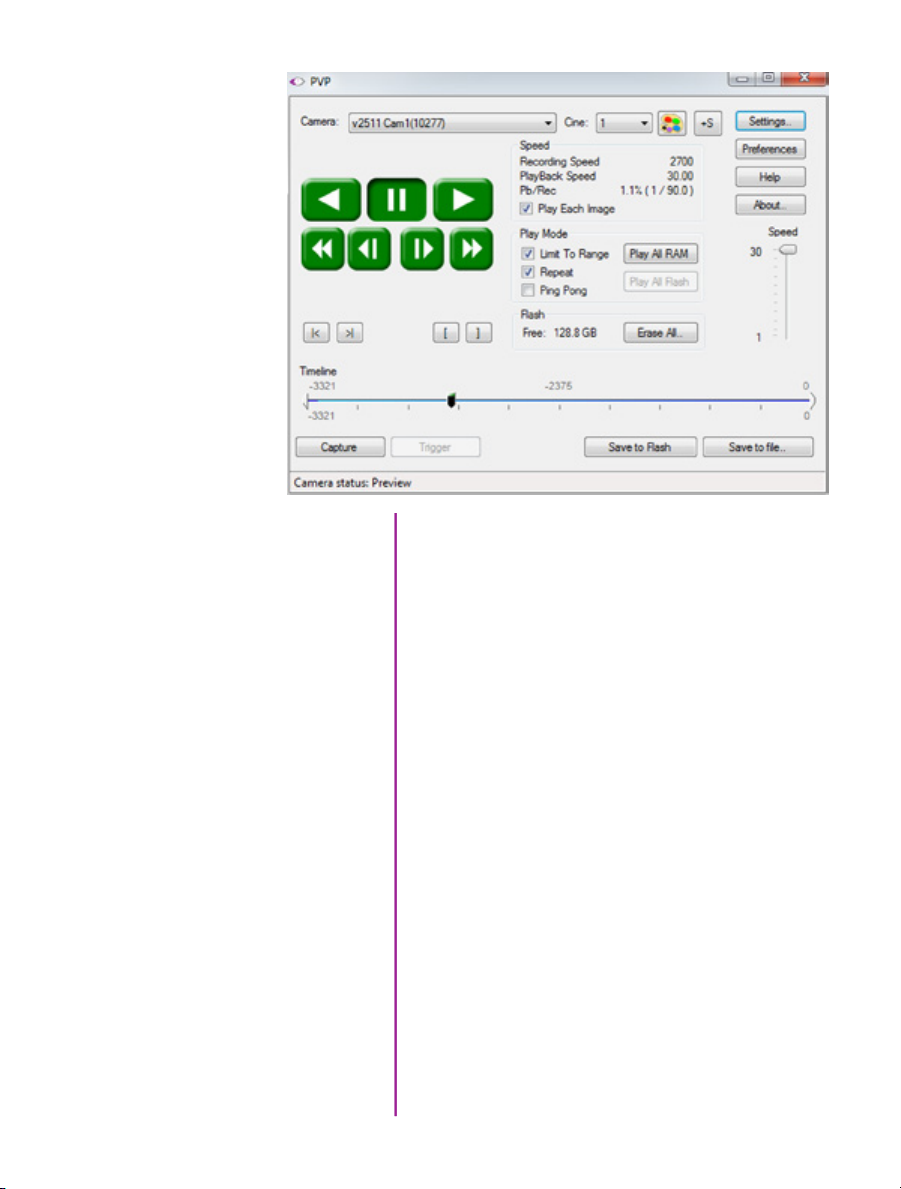
The Main PVP Window
Basic capture and playback are performed from the main
‘PVP’ window. The ‘Capture’ button starts recording to
RAM when the camera is in ‘Loop’ mode. Press ‘Trigger’
to stop recording.
Switch to the desired clip to view by selecting it in the
‘Cine:’ pull-down menu. Clips from the Phantom CineMag
are preceded by the letter ‘F’. To return to the live output,
select ‘Live.’
Scroll through a Cine by dragging the play head back and
forth on the timeline. Use the playback controls to play
forward and in reverse. Use the speed slider to change the
playback speed.
Use the ‘[‘ and ‘]’ buttons to mark in and out points. After
trimming a clip, press the ‘Save to Flash’ button to save it
to the Phantom CineMag, or ‘Save to File…’ to download
it to the computer.
It is also possible to erase the entire contents of a
CineMag by clicking the ‘Erase All…’ button.
33
Chapter 3: Phantom Software
Page 40

A B C D E F Q H
R
P
O
N
M
Camera State
A
Cine # (for multi-Cine setups)
B
Time Stamp
C
Internal Memory
D
capture & setting
Number of Frames Available
E
Record Time
F
Trigger
G
Menu Button
H
OSD Button
I
J Resolution
34
Phantom Miro LAB / LC / R Series Camera Manual
L G K J I
K Voltage / Battery Life
L Exposure Time
M Speed
N Serial Number / Name
O Cine Management
P Menu
Q CineFlash Status
R IBAT Enabled
Page 41

Miro LC Touch
4
Introduction
Camera State
Screens
The LCD Touchscreen can be used both as a viewfinder
and for touch screen controls.
The display will flip vertically when positioned upside
down (such as mounted against the side of a camera,
facing outward).
The symbol and color will change based upon the state
A
of the camera.
Live: camera is not recording to internal memory.
Displays a ‘Live’ image on the LCD and attached
video monitor.
Capture: camera is recording to internal memory
(RAM), and awaiting a trigger signal. Displays
a ‘Live’ image on the LCD and attached video
monitor.
Triggered: camera has been triggered, and is
filling internal memory (‘Post-Trigger’ frames).
Displays a ‘Live’ image on the LCD and attached
video monitor.
Cine Stored: recording has ended, and a Cine
is stored in internal memory. Displays a ‘Live’
image on the LCD and attached video monitor.
Playback: camera is in PLAYBACK mode.
RAM Cines can be selected for playback.
Cine
Time Stamp
Internal Memory
Indicates the internal memory (RAM) partition the Cine
B
is being recorded into.
Indicates the day of the
C
year/hour:minute:second:microsecond.
This ‘time line’ represents all frames available in the
D
camera’s internal memory (RAM buffer / circular buffer)
The ‘T’ symbol above the time line represents the
user-defined trigger point.
Chapter 4: Miro LC Touch Screens
35
Page 42

Number of Frames Available
Indicates the exact number of recordable frames
E
available in the camera’s internal memory.
Record Time
Trigger
Menu Button
OSD Button
Resolution
Volatge / Battery Life
Exposure Time
Indicates the total length of recording time
F
(in minutes and/or seconds).
Triggers the camera. Trigger is also available from
G
the red button on the front of the camera body,
or via capture port.
Turns on/off ‘Menu’ icons. Exiting the menu is an
H
electronic reset of the touch screen. Reset takes about
5 seconds. Double-clicking the square button also
resets the screen.
Tapping the center of the screen will
also bring up menu icons.
Turns on/off all on-screen displays.
I
Indicates the user-defined resolution (width x height),
J
in pixels.
Indicates the power status (counts down).
K
Indicates the user-defined Exposure Time
L
(in milliseconds or microseconds).
Speed
Serial Number / Name
Cine Management
Menu
CineFlash Status
IBAT Enabled
36
Phantom Miro LAB / LC / R Series Camera Manual
Indicates the user-defined frame rate.
M
Indicates the camera serial number or user-defined
camera name.
N
Tap to view and select Cine files stored in RAM, save
O
and/or delete to re-arm the camera.
Tap to view the main ‘Capture and Setting’ control
P
interface.
Displays the status, number of gigabytes used,
P
and size (in gigabytes) of the Phantom CineFlash.
Displays when IBAT (Image-Based Auto-Tigger)
P
is enabled.
Page 43

A B C D
H
G
main menu
F
Factory & User Settings
Capture & Settings
Menu Categories
E
Tap to display ‘Factory & User Settings’ menu used to
A
load the factory settings, access three factory-saved
presets, or store up to 6 of your own presets.
Scroll up and down for desired setting. Tap once to
B
select parameter to change.
Used to jump to menu categories in the camera’s main
C
menu list.
Chapter 4: Miro LC Touch Screens
37
Page 44

AWB
AWB (Automatic White Balance) automatically adjusts
D
the camera’s white balance.
Camera Info
Scroll Up
Scroll Down
Return
Place a non-saturated white or neutral object in the
E
center square and tap once.
Camera Info displays model, serial #, memory size,
firmware level, and current temperature readings.
Scroll up the ‘Capture & Setting’ menu.
F
Scroll down the ‘Capture & Setting’ menu.
G
Move up one level within the menu structure.
H
38
Phantom Miro LAB / LC / R Series Camera Manual
Page 45

menu description
Menu above is always available
Expanded menu (above) is displayed when
‘Advanced Settings’ is set to ‘On’
39
Chapter 4: Miro LC Touch Screens
Page 46

Setting Access
From the ‘Main’ screen tap the ‘Menu’ icon as indicated to
bring up the main ‘capture and setting control interface’.
Scroll up and down for desired setting, then tap once to
select parameter to change.
Speed
Exp. Time
Resolution
Post Trigger
Defines the ‘Speed’ (Frame Rate / Sample Rate) that the
camera will capture at. The available speeds will change
according to the ‘Resolution’ selected. Smaller resolutions
allow higher speeds.
The Resolution parameter should be defined
before setting the Speed.
Defines the amount of time the sensor is exposed to light
(in μs of exposure time and degrees of shutter angle).
A smaller exposure time (shutter angle) reduces the
chance of motion blur.
Resolution is the number of pixels used to capture an
image. For example, Miro M120, if 1920 x 1200
(width x height) is set, the full sensor space is available.
Smaller resolutions allow higher recording speeds.
The image aspect ratio will be displayed with
the defined ‘Resolution’ setting.
Defines the number of frames past the trigger point to be
stored in the camera’s internal memory (RAM / circular
buffer).
Auto Exposure
40
Phantom Miro LAB / LC / R Series Camera Manual
Adjusts the overall exposure of the image based on the
light level measured within a user defined area of interest.
The default is a 50% average exposure. As the lighting
changes, the camera automatically adjusts the shutter
speed to maintain a constant light level in the defined
area.
This feature should not be enabled while performing a CSR, (Current Session Reference).
Once enabled EDR (Extreme Dynamic Range)
will be disabled.
Page 47

Exposure Index
EI (Exposure Index) is a reference value for the ISO level of
the current shooting settings. A camera’s default EI value
is measured at the default gamma of 2.222. Increasing
the EI adds gain to the video image, the more gain that is
added the more digital noise will be visible in the resulting
Cine. Vision Research recommends maintaining the EI as
close to default as possible for best image quality.
Video Format
Color Bars
Production Area
White Balance
Defines the video signal format the camera will transmit to
a monitor. Formats include; NTSC, PAL, HD-SDI (1080psf,
1080i, 720p).
These are SMPTE Color bars, generated by the camera
and output over the video signal. They are used for setting
up a video monitor.
The camera will show the PA (Production Area) specified
placing a red rectangle over the image. The production
area is an overlay and is not recorded in the RAW data.
The camera’s white balance can be set with the AWB
on the upper right or manually by adjusting the color
temperature and color compensation.
Color Comp.
Color temperature adjusts the red and blue components of
white balance.
Color Compensation (CC+0) adjusts the magenta and
green components of the white balance.
41
Chapter 4: Miro LC Touch Screens
Page 48

Master Gamma
Gamma is the nonlinear relationship between signal
level and brightness output of pixels, (a small signal level
change at low voltage produces a larger variation in
brightness than the same change in level at high voltage).
A linear gamma would have the value of 1.0. The camera’s default gamma setting is 2.2, which is a standard
Rec709 compensation for most video monitors.
IBAT Enable
IBAT Area
IBAT Position
IBAT Speed
IBAT Sensitivity
RAM Partitions
At End of Recording
Language
Advanced Settings
With IBAT (Image-Based Auto-Trigger) Enable set to ‘On’
the camera triggers itself when the image changes occur
in a selectable region of the frame.
Defines the size of the area (width x height) in pixels to
check for an auto-trigger event.
Defines the position of the ‘IBAT Area’ from the top left
of the image at 0,0.
Defines the number of frames (interval) between updates
the auto-trigger region is checked.
Defines the amount a pixel value must change for
auto-trigger purposes.
Defines the number of partitions, (15 segments maximum), the camera’s internal memory buffer (RAM) will be
evenly divided into.
End of recording (automatic actions) can be set to:
Play and Save, Play and Restart, Save and Restart, Play,
Save and Restart.
Changes the menu display to the desired language.
With ‘Advanced Settings’ set to ‘Off’, the menu ends here,
and all advanced parameters are set to the camera’s
defaults.
Auto Exp. Comp.
42
Phantom Miro LAB / LC / R Series Camera Manual
With ‘Advanced Settings’ set to ‘On’, the menu expands
and the camera’s full functionality can be accessed.
Allows for plus / minus two f-stops from the default value
of 50% of average exposure.
Page 49

Shutter
This activates shutter-off mode for PIV applications.
EDR
Frame Burst
Burst Period
Auto Black Ref.
Save Region Start
EDR (Extreme Dynamic Range™) sets a unique
exposure time (defined in microseconds or a percentage
of the defined ‘Exposure Time’) to pixels that may become
saturated, (over exposed).
This feature should not be enabled while
performing a CSR, (Current Session Reference).
Once enabled ‘Auto Exposure’ will be disabled.
Sets the number of frames in a burst, (‘off’ disables Burst
Mode).
Sets the interval between frames in a burst (defined in
microseconds).
When set to ‘On’ a black reference operation will be
performed when the camera is placed into the capture
or ‘waiting for trigger’ mode with the results being saved
with the Cine.
Sets the first frame for automatic functions like auto-save
to CineFlash and Auto-Play to video. If not selected the
first frame will always be the beginning of the full
recording.
Save Region End
Frame Sync
Sets the last frame for automatic functions like auto-save
to CineFlash and Auto-Play to video. If not selected the
last frame will always be the end of the full recording.
This field instructs the camera to utilize one of the
following three frame sync clock sources:
• Internal - instructs the camera to utilize its’
internal crystal oscillator to drive the camera’s
‘Speed’ (sample / frame rate).
• External - should be selected when an externally
supplied frame sync clock pulse is supplied to drive
the camera’s sample rate.
• IRIG - should be selected when an IRIG-B signal is
supplied to drive the camera’s sample rate.
43
Chapter 4: Miro LC Touch Screens
Page 50

Trigger Polarity
Defines whether the ‘Rising Edge’ (leading edge) or
‘Falling Edge” (trailing edge) of a TTL supplied input trigger
signal is used to trigger the camera.
Trigger Filter
Frame Delay
Aux Signal
Ready Deasserts
Saturation
Master Black
Specifies the length of time (in microseconds) the trigger
signal state (high / low) must be held to be a valid trigger
signal.
If ‘Trigger Polarity’ is set to ‘Rising Edge’ the
signal must be held low for a minimum of
10-times the ‘Trigger Filter’ time prior to going
high to be a valid trigger signal.
Sets a delay time (defined in microseconds) between the
‘Frame Sync’ clock pulse and the frame capture to provide
a phase shift in the timing.
Sets the signal type to be activated on the ‘Auxiliary’ pin of
the capture connector.
Defines when the ‘Ready’ signal is turned off.
Adjust the color ‘Saturation’ of the images being displayed. Increasing the value results in the images being
displayed with more brilliant color, while decreasing the
value results in the images being displayed with less
dazzling color.
The ‘Master Black’ (Pedestal) parameter is used to change
the voltage level corresponding to black or to the maximum limit of black peaks.
Pedestal
Gamma
44
Phantom Miro LAB / LC / R Series Camera Manual
Gain
‘Gain’ will raise or lower the gain in each independent
color channel when adjusted.
‘Pedestal will raise or lower the black level of each independent color channel when selected.
‘Gamma’ will apply an independent gamma curve to each
color channel.
Gain, Pedestal, and Gamma settings are
applied on top of the overall gamma and color
corrections.
Page 51

Matrix
Color Matrix is an advanced color matching tool, which
previously was reserved for video engineers to match the
HD-SDI output of cameras in a broadcast environment.
In Phantom Miro M- and LC-series cameras, a user ‘Matrix’ can be specified to fine-tune the color of both
the Cine image and HD-SDI output.
By adjusting the user ‘Matrix’ the image can be finely
tuned, so that individual colors can be adjusted in terms of
tint and saturation. A common use for this is to match the
color with another camera on the same shoot accurately.
Tone
PA Offset
Tone allows manual control over the tone curve of
the image. Tone curves change the shadow / highlight
relationship between the original values (on X axis) and
resulting values (on Y axis).
Tone curves can be useful to boost mid tones within
the image without affecting highlights or shadows, for
example. They can also be used to push the darks lower,
which may result in richer images when details in the
shadows are not required. There is a relationship with
overall image gamma, which has a predefined curve,
which is the equivalent of Rec709.
The Production Area Offset is used to move a userdefined ‘Production Area’ displayed on the LCD or
attached monitor. By default, the ‘Production Area’ is
displayed in the center of the image display area.
45
Chapter 4: Miro LC Touch Screens
Page 52

Menu Access
Select Setting
Click the ‘Square’ button once to bring up touch screen
menu. Tapping the center of the screen will also bring up
‘main menu’ icons.
Tap the menu icon to bring up the main ‘capture and
setting’ control interface.
Scroll up and down for desired setting, then tap once to
select parameter to change.
Set Parameter
On the right, + and - symbols will appear when
applicable, and a keyboard symbol can also be selected
for data entry.
The keyboard/data entry menu allows you to enter any
available value, then tap the ‘return’ key to accept.
setting parameters
46
Phantom Miro LAB / LC / R Series Camera Manual
Page 53

Factory & User Settings
Click the ‘Factory & User Settings’ icon.
Load the factory settings, access three factory-saved
presets, or store up to 6 of your own presets.
When saving a user-setup, enter a name and tap the
‘return’ button to save it. Any of the three factory saved
presets can be modified or overwritten.
When loading any of the user settings or factory defaults,
you must tap to confirm or cancel.
Chapter 4: Miro LC Touch Screens
47
Page 54

M
L
A B C D E F G
K
Camera State
A
Time Stamp
B
Internal Memory
C
file management
48
Phantom Miro LAB / LC / R Series Camera Manual
Number of Frames Available
D
Record Time
E
CineFlash Status
F
Menu Button
G
J I H
OSD Button
H
I Play Cine
J Cine List
K CineFlash Management
L Erase Cine
M Return
Page 55

GEDCBA H
CineFlash Status
Play Cine
Cine List
CineFlash Mangement
Erase Cine
See ‘Capture & Setting’ earlier in this chapter for
descriptions.
See ‘Main Menu’ earlier in this chapter for description.
M
Displays the status of the Phantom CineFlash, space
F
used and the number of frames being saved.
Opens the ‘Play’ Cine screen.
I
Used to select a Cine from the list to play or erase
J
(asterisk indicates Cine was not yet saved).
Opens the CineFlash Management screen (displays list
K
of Cine files stored on CineFlash drive).
Erases selected Cine from the camera RAM (displays
L
when a Cine is selected).
Delete individual takes, or tap ‘XCF’ to format
(secure erase) the drive.
Chapter 4: Miro LC Touch Screens
49
Page 56

A B C D E F G H I J K
play
T
MNOPQRS L
Camera State
A
Cine
B
Mark In Point
C
Image Location
D
Time Stamp
E
Internal Memory
F
Mark Out Point
G
Number of Available Frames
H
I Record Time
J CineFlash Status
K Menu Button
50
Phantom Miro LAB / LC / R Series Camera Manual
OSD Button
L
M Save to CineFlash
N Mark Out
O Forward
P Forward 1-Frame
Q Stop / Pause
R Reverse
S Mark In
T Return
Page 57

Cine
KIHFEA L
See ‘Capture & Setting’ earlier in this chapter for
descriptions.
See ‘Main Menu’ earlier in this chapter for description.
T
Indicates the internal memory (RAM) partition Cine
B
being reviewed.
Mark In Point
Image Location
Mark Out Point
CineFlash Status
Save to CineFlash
Mark Out
Forward
Forward 1-Frame
Stop / Pause
Reverese
Mark In
Indicates the first image of the entire Cine to be saved.
C
Indicates the displayed frame’s location within the
D
stored Cine file.
Indicates the last image of the entire Cine to be saved.
G
Displays the status of the CineFlash and the frame
J
number being saved (counts up).
Saves Cine file to CineFlash.
M
Sets the end point of the Cine file to save.
N
Plays the Cine file. Tap multiple times to speed up
O
playback.
Advances the Cine file one image.
P
Pauses playback. When paused button changes
Q
to ‘Reverse 1-Frame’ button.
Plays the Cine file in reverse. Tap multiple times to
R
speed up playback.
Sets the starting point of the Cine file to save.
S
Apply a long press over the ‘Mark In’ and
‘Mark Out’ buttons to reset .
Chapter 4: Miro LC Touch Screens
51
Page 58

52
Phantom Miro LAB / LC / R Series Camera Manual
Page 59

Download & Image
5
Introduction
PCC Software Solutions
Converting Cine Files
Processing
The images recorded on the camera’s RAM or
Phantom CineMag are stored in a Vision Research
proprietary RAW (uncompressed) file structure called
a ‘Cine’ file.
These Cine files can be converted to industry-standard
formats (ProRes, H264, DPX, DNG, TIFF, JPEG, and
more) with PCC software provided by Vision Research.
Phantom PCC and PVP software are only compatible
with Windows operating systems; however, there are
third party solutions available for working with Phantom
cameras in Mac OSX.
Windows-based PCC software provides the ability to
convert cine files into a number of other formats.
Single cine files can be converted by selecting the
desired format from the ‘Save as Type’ selection list in
the ‘Save Cine’ dialogue window.
The file formats above the separator line in the
‘Save as Type’ selection list are ‘movie-like’ formats
(meaning the entire clip will be saved as a single file)
while the formats below the line are image formats
(meaning each frame of cine will be saved as a
sequence of images).
Apply a long press over the ‘Mark In’ and
‘Mark Out’ buttons to reset .
To convert a cine to a ‘movie-like’ format select the
desired format from the list, navigate to the destination
folder, assign a file name to the clip and save.
Some valuable parameters can be found in the ‘advanced settings’ window, such as the particular codec
(coder / decoder). In the case of ProRes, the default is
4:2:2 HQ; however, other options are available.
Chapter 5: Download & Image Processing
53
Page 60

Other formats, like .avi and .mp4 allow the compression
ratio to be entered. The lowest compression is the default.
To convert a cine clip into a sequence of images (frames)
you must add one of the following annotations to the
end of the file name: ‘!n’ or ‘+n (where n is the number
between 1 to 8). This will assign the sequential frame
numbers to the file name for each frame being created.
Example: image_!5.tif
The ‘!’ annotator instructs the software to append the
cine’s image number (relative to the trigger point) to the
file name. If the first frame in the clip is - 100, then the
first converted frame will have the name: image_-00100.
tif.
The ‘+’ annotator will add frame numbers starting from 1.
Example: image_+5.tif
This will cause the first converted frame to have the name:
image_00001.tif
Ensure all image adjustments have been applied prior to initiating the conversion process.
All metadata (gain, gamma, saturation, etc.)
will be embedded into the converted images.
Batch Convert
54
Phantom Miro LAB / LC / R Series Camera Manual
The ‘Batch Convert Files’ toolbar button can be used to
convert a single, or multiple saved cine files into any one
of the supported file formats.
Use the shift and/or control keys, to select the cine files
you wish to convert in the ‘Open Cine’ dialogue window,
then click the ‘Open’ button.
Navigate to the destination folder, in the ‘Multifile Convert
Destination’ dialogue window, and select the file format.
Page 61

The ‘File Name’ will depend upon the type of file format
you are converting to.
If you are converting the Cine file into a ‘movie-like’
formats leave the file name as ‘All selected files’. The
software automatically assigns the original file name
to the converted file and appends the appropriate file
extension.
However, if you are converting the file into a sequence of
images, you need to enter the Annotation only detailed in
the ‘Convert a Cine’ topic earlier in this chapter.
Example: +4
The software automatically creates a separate folder for
each of the files being converted, assigns the original file
name, and appends the appropriate image number and
file extension to each image.
Once the ‘Convert’ button is clicked a progress window
appears. Each converted cine will be placed in its own
folder named after the original cine file.
55
Chapter 5: Download & Image Processing
Page 62

For details on how to use the various PCC measurement tools can be found in the Phantom (PCC) Camera Control
56
Phantom Miro LAB / LC / R Series Camera Manual
Application Help File > Step-by-Step Procedures > Play Panel Procedures > Measurements.
Page 63

6
Measurements
Introduction
High-speed photography is as much of an engineering tool
as an oscilloscope, spectrum analyzer, or logic analyzer.
The photographic technique enables us to visualize and
analyze motion, especially motion that is too fast for the
human eye or conventional cameras to perceive.
For decades, Phantom Cine (high-speed digital video)
files have been used to measure moving objects by
the defense, scientific and research, and industrial
communities to extract and quantify motion from a file.
As high speed digital cameras continue to make
advancement in recording speeds, sensitivity and
resolutions so must the motion analysis software used to
extract the data they record. Data that allows the defense
community to examine the speed, angle and angular
speed a shock wave from an explosive device.
Information automotive engineers require to evaluate
the safety and effectiveness of an airbag design by
determining the time, speed, and angle it takes the airbag
to deploy fully. Studies by the scientific and research
community analyzing human locomotion by measuring
the angle, a knee joint bend and the compression the
knee joint endures while running, or the speed of a
lightning bolt. Not to mention manufacturers needing to
measure the angular speed (Revolutions Per Minute) a
new hard drive motor can spin without causing damage
to the disk, or being able to measure the effect the angle
of impact a golf club will have on the rotational speed of a
golf ball.
The ability to analyze all of this data quickly and
accurately inherently decreases product development
time, and more importantly reduces research and
development expenditures. Of course extracting this
information from a digital high speed video is only as
good as the tools used to accomplish it.
Chapter 6: Measurements
57
Page 64

PCC Multi-Layer Graphical User Interface automatically tracks golf club head to calculate swing speed, path, and acceleration.
Using 2-D motion analysis tools, such as Vision Research,
PCC (Phantom Camera Control) software calculates this
valuable data. With today’s software, the end-user can
perform timing, position, distance, velocity, angle and
angular speed measurements, and track multiple points
or objects to compute and graph their XY-coordinates,
speed, or acceleration. PCC, for example, provides several
edge detection algorithms and image processing tools to
improve the measurement process. The measurement
technology provides a motion analysis system that
harmonizes measured data with images. In this chapter,
we will review the various PCC measurement capabilities.
Units of Measurement
58
Phantom Miro LAB / LC / R Series Camera Manual
Units of Measurement specify the computing and
reporting unit for distance, speed, acceleration, angle,
and angular speed measurements.
Page 65

Establishing a measurement scale is required to set a
specified number of pixels in the image equal to a scale
unit size, such as millimeters, meter, inches, feet, or pixels.
To define a measurement scale, the analyst needs to
select two points in the image with a known scale, then
specify that scale size. Once created, all measurements
are computed and displayed using the scale unit. If no
measurement scale exists, the default scale will be 1 pixel
= 1 pixel.
Timing
Coordinate
Distance, Angle, Speed
To perform timing measurements accurately, a time stamp
(date and time) is embedded into every frame captured.
The PCC software function, for example, calculates the
time difference between two event frames (start / end of
an event) or from the captured image being displayed to
the trigger (t0) frame automatically.
Coordinate measurements are calculated from an Origin
point pixel, by default the top-left corner of the image;
however, the Origin can be changed when performing
measurements. Each coordinate consists of two numbers
(x1, y1) indicating the position of a pixel in the image on
the two-dimensional plane from the Origin point.
Using ‘Distance and Angle and Speed’ instant
measurement tools makes analyzing launch speed,
angle, and angular speed or the revolutions of a rotating
object extremely simplistic.
They allow engineers’ developing large caliber weaponry
to analyze the effect the design of the shell has on the
projectile trajectory based on launch speed and angle
to determine the optimal performance, or manufacturers
of scientific equipment like anemometers to determine
the best size and type motor to enhance their product by
performing angular speed (rotational measurements) on
the motors used to generate an electric current as they
rotate.
59
Chapter 6: Measurements
Page 66

PCC measures the distance from the Origin point to a
chosen point, and the angle made by the Origin and Ox
axis of the selected point using the Distance and Angle
and Speed: Origin + 1 Point instant measurement tool.
Given the coordinates of two points on the image plane,
the distance (d) between the points is calculated using the
following formula: d=√((x2-x1)2) + (y2-y1)2).
If the Origin and the chosen point are on the same image,
PCC will calculate distance and angle only; however, if the
Origin and the selected point are on different frames, the
software also calculates speed and angular speed.
Speed (s) is calculated using the formula: s=d/dt, where
d = measured distance, and dt = [time of the point frame]
– [time of the origin frame] if point and origin are on
different frames.
Angular speed is calculated using the formula: as=a/dt,
where a = measured angle, and dt = [time of the point
frame] – [time of the origin frame] if point and origin are
on different frames.
60
Phantom Miro LAB / LC / R Series Camera Manual
The ‘Angle and Angular Speed: 3 Points’ instant
measurement tool from PCC calculates the angle made
by three points (two lines with a common reference point)
while the Angle and Angular Speed: 4 Points calculates
the angle formed by four points [Pt.1 Ref.1 and Ref.2
Pt.2]; two lines without a common reference point.
Page 67

If all the points are in the same image when performing
three or four-point measurements, the software only
calculates the angle. In order to compute angular speed
the first point and the reference point must be on the
same image while the second point (three-points
measurements) or reference point 2 and point 2
(four-point measurements) must be on different images.
Angular speed is calculated using the formula: as=a/dt,
where a = measured angle, dt = [time of the last point
frame] – [time of the first point frame] if first and last
points are on different frames.
PCC calculates speed (mph) and angular speed (rpm) of the fan motor using Distance,
and Angle, and Speed: Origin + 1 Point measurement tool.
These measurement tools are exceptional when analyzing
a rotating object.
The ability to measure an object, like a projectile rotating
in mid-air, to determine its angular speed can be applied
in other sciences, for example, the way 2 x 4 board could
tumble in hurricane-force winds can be applied by
61
Chapter 6: Measurements
Page 68

Collect Point (Tracking)
manufacturers who develop unbreakable glass windows,
or engineers developing stabilizers for aircraft.
PCC also provides a Collect Point (tracking) tool to
compute the position, speed, acceleration, and / or
generate motion graphs of a point (or object) or multiple
points (up to 99), with respect to the image plane, over
time. The analyst can use one of two methods to track
2D motion (Automatic or Manual).
Example of three points being tracked. The graph plots and displays, by default, the x-axis coordinate
62
Phantom Miro LAB / LC / R Series Camera Manual
of all points / targets from the Origin point.
With Automatic Tracking, the analyst needs to define a
rectangle (width and height in pixels) around a template
image region (the point being tracked). The analyst
defines a second rectangle that the tracking algorithm
should search in (how large of an area to search) for the
previously tracked point. A value equal to the track point
indicates that the tracking algorithm should search in a
region as large as the initial region size.
Page 69

Data Acquisition
Larger values will result in greater search areas,
which will take a longer time to search. Typically, this
parameter is set two to three times the size of the initial
image template (defined in pixels). When initiated, the
software will automatically find and track the template
region as it progresses through each frame.
Manual Tracking requires the analyst to select every point
being tracked for each frame. With either method all
tracked points are logged to a measurement file that can
be used to generate a coordinate, speed, or acceleration
spreadsheet easing report generation.
To investigate the effect environmental conditions may
have on the recorded data, a National Instrument™
USB- or M- Series Data Acquisition (DAQ) module can
also be used to acquire data from a wide range of
sensors, and synchronize it with slow-motion video images
recorded on a Phantom camera, using Phantom Camera
Control (PCC) software.
Chapter 6: Measurements
63
Page 70

SDK (System Developer Kit)
Phantom camera control, and Cine playback, analysis
and measurements can be customized to meet the
specific test protocols using the Phantom System
Developer Kit (SDK) for LabVIEW (Laboratory Virtual Instrument Engineering Workbench) or MATLAB
(matrix laboratory) drivers.
The LabVIEW SDK contains visual instrument (VI) files
needed to call Phantom SDK functions from LabVIEW,
various utilities, and demo applications. This SDK uses
the LabVIEW interface to shared libraries to call functions
from Phantom libraries.
64
Phantom Miro LAB / LC / R Series Camera Manual
The MATLAB SDK contains header files needed to call
Phantom SDK functions from MATLAB, function wrappers,
a simple object-oriented layer and demo scripts. This
SDK uses the MATLAB interface to shared libraries to
call functions from Phantom libraries.
SDKs allow, for example, automotive manufacturers
to create command line scripts to control a Phantom
camera directly from a computer or run in a Graphical
User Interface specifically designed to perform or analyze
airbag tests with having to use PCC. Anyone who wishes
to have more control over their Phantom camera or the
Cine files record would benefit using one of these
Phantom System Developer Kits.
Page 71

Conclusion
Digital high speed video has been and continues to be a
useful test and measurement tool.
Along with PCC software, the need to use calculators
or slide rules to perform complicated mathematical
calculations to compute distance, speed, angle, angular
speed, or acceleration measurements of single or multiple
points from 2D images has been eliminated.
The ability to perform these calculations with just a few
clicks of a mouse button allow engineers, science and
researchers, and developers will significantly reduce
research and development time thereby increasing
productivity.
These tools provide them with the ability to conduct
even more precise and accurate analyses of ballistics,
explosions, weapon’s development, trajectory,
biomechanics, sport performance, flow analysis, crash,
combustion, and stress studies, just to mention a few.
65
Chapter 6: Measurements
Page 72

66
Phantom Miro LAB / LC / R Series Camera Manual
Page 73

CineFlash &
7
Introduction
CineFlash Dock
The Phantom CineFlash is a powerful component of the
Phantom Miro LAB / LC / R product lines, enabling Cine
raw footage to be quickly transferred from the camera’s
RAM to safe, non-volatile storage. These lightweight,
solid-state storage devices are hot-swappable and
designed to keep you shooting on the go.
There are several benefits to Phantom CineFlash drives:
• Security. Immediately save your high-speed images
from the camera’s dynamic RAM to CineFlash
non-volatile memory so you have a secure copy of
your shot.
• Productivity. Eliminates the need to download the file
after each shot, meaning less down-time in between
takes.
• Quality. Files saved to the CineFlash are always
saved in the Cine raw format, which maximizes
image quality and workflow options.
• Portability. Whether using a Phantom RCU, the LCD
interface or an auto-save setup, when saving to the
CineFlash, there’s no need to connect the camera to
a PC during capture.
Once the CineFlash drive is full, download Cine raw files
over the camera’s Ethernet connection or via the Phantom
CineFlash Dock’s E-Sata or USB 3.0 connection. Using
the CineFlash Dock and appropriate drivers, you can
mount the CineFlash on a PC or Mac computer and easily
manage your Cines files.
Every Miro LAB / LC / R Series camera purchase comes
standard with a Phantom CineFlash drive and CineFlash
Dock. Phantom CineFlash drives are available in 120GB,
(Gigabytes) or 240GB sizes.
Chapter 7: Phantom CineFlash & CineFlash Dock
67
Page 74

Phantom CineFlash Installation
Open the Phantom CineFlash compartment door. Carefully
align the insertion key guards, and slide the CineFlash
into the camera until it is properly seated, then close the
CineFlash compartment door.
Phantom CineFlash Removal
Re-open the CineFlash compartment door.
Prior to removing the Phantom CineFlash verify that it is
safe to remove it by ensuring the ‘CineFlash Recording
Indicator’ (located inside the CineFlash compartment on
the lower right-hand side) is inactive.
If the indicator is active (red), do not remove the CineFlash
because a Cine is being recorded to the CineFlash.
68
Phantom Miro LAB / LC / R Series Camera Manual
Page 75

Phantom CineFlashDock
Installation
Footage from Phantom Miro LAB / LC / R camera models
is stored on CineFlash drives as 10-bit log raw cine files.
The CineFlash drive is formatted using the Linux Ext2 file
system, and can be accessed from the camera body over
Ethernet, or remotely using a Phantom CineFlash Dock via
USB3 or eSATA.
The CineFlash Dock is compatible with both PC and Mac
computers once the appropriate EXT2 driver is installed.
This allows 3rd party solutions that can read Cine raw files
to see the file directly from the CineFlash. This also means
that you can “drag and drop” the file from the CineFlash to
local storage on a computer.
Phantom CineFlash Docks shipped after October 1, 2015
include the recommended Paragon ExtFS driver on a USB
flash drive, which can be installed on a single Windows OS
or Macintosh OSX computer, and installation instructions.
During the installation process, you will be asked to provide a ‘Product Key’ and ‘Serial Number’ (located on the
bottom of the Phantom CineFlash Dock – also beginning
October 2015) to validate the single-user license.
Please note that the Product Key and Serial Number
are bound to the computer on which the ExtFS driver is
installed, not the Phantom CineFlash Docking Station.
CineFlash Dock users without the USB drive or product
key can download and purchase the latest Paragon ExtFS
drivers at https://www.paragon-software.com/
Once installed, the CineFlash will automatically be
mounted when inserted into the dock. The CineFlash
is less tolerant of being removed from the dock (disconnected from the computer) than a typical USB drive.
Therefore, you should ALWAYS unmount the CineFlash
before removing it from the dock or disconnecting the
dock from the computer if it has a CineFlash in it. This
ensures that all data is written and flushed to the disk
before removing the drive.
Users can access, play, edit and save the cine files
using Phantom PCC or the Phantom CineViewer software
(Windows only). To view and play the cines on a Mac, the
GlueTools Phantom Cine plugin is recommended and is
available from GlueTools.com
Chapter 7: Phantom CineFlash & CineFlash Dock
69
Page 76
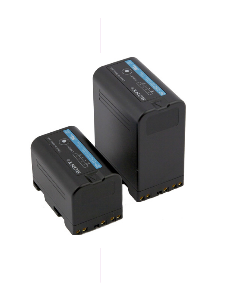
70
Phantom Miro LAB / LC / R Series Camera Manual
Sony BP-U60 Lithium-ion
Rechargeable Battery
Sony BP-U30 Lithium-ion
Rechargeable Battery
Page 77

8
Accessories
Batteries & Battery Charger
The Sony BP-U30 and BP-U60 are lithium-ion batteries
designed for professional video shooting in both the field
and the studio. These BP-U Series compact lithium-ion
batteries boast high power in a compact body.
The batteries are equipped with the professional ‘INFO’
function that intelligently communicates battery status
data to the camera.
The remaining capacity of the battery is displayed on the
LCD monitor and viewfinder when the camera is powered on. This intelligent battery-management function
allows operators to monitor the battery status easily and
accurately.
The BP-U30 and BP-U60 also have LED displays to
indicate the remaining capacity of the battery at the push
of a button on the battery itself.
The BC-U1 Battery Charger can be used to charge one
BP-U60 or BP-U30 battery at a time. And provides a
12 VDC, 2.0A power output.
BC-U1 Battery Charger must
be used to recharge the
batteries.
Batteries do not recharge
through the camera.
BC-U1 Battery Charger
71
Chapter 8: Accessories
Page 78

Specifications BP-U30 Lithium-ion Battery
BP-U60 Lithium-ion Battery
Dimensions (W x H x D)
Mass
Maximum / Nominal Voltage
Miro Run Time
Approximate Charge Time
(Using the BC-U1)
Operating Temperature
Remaining Capacity Display
Power Requirements
Power Consumption
Operating Temperature
Dimenisons (W x H x D)
Weight
DC Output
Number of Mountable Batteries
Chargable Battery
1 11/16 x 3 1/4 x 2 3/4 in
(41.5 x 82.5 x 69.7 mm)
8 oz (220 g) 15 oz (350 g)
16.4 VDC / 14.4 VDC 16.4 VDC / 14.4 VDC
45 minutes 90 minutes
130 minutes 170 minutes
-4 to +113 °F (-20 to +45 °C) -4 to +113 °F (-20 to +45 °C)
Four LED (20, 40, 60, and 80%) Four LED (20, 40, 60, and 80%)
1 11/16 x 3 1/4 x 2 3/4 in
(41.5 x 82.5 x 69.7 mm)
BP-U30 Lithium-ion Battery
100 VAC to 240 VAC, 50/60 Hz
38 Watts
+32 to +113 °F (0 to +45 °C)
5 1/8 x 1 13/16 x 3 7/8 in (128 x 45 x 98 mm)
12 oz (330 g)
12V, 2.0A
1
BP-U90 / BP-U60 / BP-U30
Supplied Accesories
Approximate Charge Time
72
Phantom Miro LAB / LC / R Series Camera Manual
(1) Operating Instructions
(1) DC Output Cable
(1) Warrenty Booklet
170 min (BP-U60, 57 Wh) / 130 min (Bp-U30, 28 Wh)
Page 79

Vision Research recommends the following procedure for safe battery installation and removal.
Only Sony BP-U30 and BP-U60 batteries are guaranteed. Larger, heavier batteries should not
be used. Failure to follow this procedure could result in physical damage to the camera, which
must be repaired at a Vision Research service center.
Battery Installation
Carefully insert the battery just above the terminals.
Notice the key guides on the sides of the battery and
camera. Insert battery either bottom-first or perfectly
straight, then press down gently to lock in place.
Never insert the battery at a top-first angle.
Battery should lower smoothly, then snap in place. Guides
will ensure the battery lowers over the terminals perfectly
straight.
Chapter 8: Accessories
73
Page 80

Battery Removal
Slide the battery lock, on the top of the camera, forward,
and lift the battery up and back to remove.
RCU-2 (Remote Control Unit)
The Phantom Remote Control Unit (RCU) is a small,
lightweight, hand-held controller, which allows you to
adjust most settings on your camera as well as view and
save recorded cines to the CineMag. The RCU is available
in both wired and wireless versions. Both versions will
connect with an included 5 meter cable direct to the back
of the camera. It includes a Bluetooth dongle that allows
for operation from up to 100 meters. Alternatively, the
wireless model includes a Bluetooth dongle that allows for
operation from up to 100 meters.
The 5" active TFT display is easy to use – even outdoors.
The display can act as an HD-SDI video monitor, a
full-featured touch-screen controller, or both. An SDI cable
connection is required to view the HD-SDI output from the
camera on the RCU screen. Video is not transmitted via
Bluetooth.
Remote Control Unit
74
Phantom Miro LAB / LC / R Series Camera Manual
Page 81

Miro Mini Break Out Box /
Capture Cable
A B C D E F
The Miro ‘Capture’ port is compatible with a multi-bnc
capture cable and Phantom Miro Mini Break out Box
(commonly known as the Miro MiniBOB). Both accessories
provide the same functions. However, the Miro MiniBOB
is designed for better cable management enhancing the
Miro camera’s capability.
Miro Mini Break Out Box
Definitions of the available
MiniBoB auxiliary signals:
F-Sync (input / output): Connect an
external source, including the F-Sync
from a second Phantom camera, to
drive the camera’s frame rate. Use in
combination with Sync: External.
Event (input): When the Event
signal is active, frames are tagged
with an Event marker (as metadata).
These events can be searched or
referenced during playback.
Strobe (output): Signal goes low
for the duration of each frame’s
exposure.
MemGate (input): When MemGate
signal is active, the camera stops
recording into its internal memory
(frames are discarded).
Ready (output): When Ready signal
is high, it indicates that the camera is
in capture mode. Using PCC, signal
can be set to go low at trigger or at
the end of recording.
Video Out / Analog video (NTSC / PAL)
A
TC In / TimeCode In (IRIG-B)
B
TC Out / TimeCode Out (IRIG-B)
C
Aux 1 / F-Sync, Event, Strobe, MemGate
D
Aux 2 / Ready, Strobe
E
Trigger
F
IRIG-In (White)
A
Trigger (Red)
B
Video Out (Green)
C
F-Sync / Auxilary (Black)
D
IRIG-Out (Blue)
E
Capture Cable
75
Chapter 8: Accessories
Page 82

mechanical drawings
76
Phantom Miro LAB / LC / R Series Camera Manual
Miro R Front View
(Body Type I)
Miro R Rear View
(Body Type I)
Page 83

9
Support
Miro LC Front View
(Body Type I)
Miro LC Rear View
(Body Type I)
Chapter 9: Support
77
Page 84

Miro R Left View without Battery
(Body Type I)
Miro R Left View with Battery
(Body Type I)
78
Phantom Miro LAB / LC / R Series Camera Manual
Miro R Left View with CineFlash
(Body Type I)
Page 85

Miro LC Left View
(Body Type I)
Miro R Right View
(Body Type I)
Chapter 9: Support
79
Page 86

Miro LC Right View
(Body Type II)
80
Phantom Miro LAB / LC / R Series Camera Manual
Page 87

Miro R Top View
(Body Type I)
Miro R Bottom View
(Body Type I)
Chapter 9: Support
81
Page 88

Miro LC Top View
(Body Type II)
82
Phantom Miro LAB / LC / R Series Camera Manual
Miro LC Bottom View
(Body Type II)
Page 89
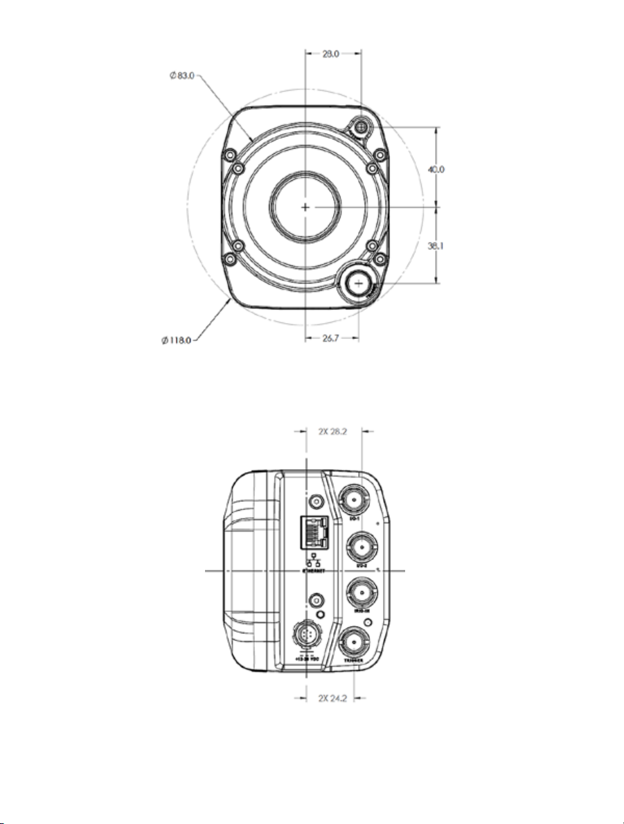
Miro LAB Front View
(Body Type III)
Miro LAB Rear View
(Body Type III)
83
Chapter 9: Support
Page 90

84
Phantom Miro LAB / LC / R Series Camera Manual
Miro LAB Right View
(Body Type III)
Miro LAB Left View
(Body Type III)
Page 91

Miro LAB Top View
(Body Type I)
Miro LAB Bottom View
(Body Type I)
Chapter 9: Support
85
Page 92

A
B
C
indicators
D
E
Miro LAB / LC / R Series
A
B
C
E
86
Phantom Miro LAB / LC / R Series Camera Manual
D
Miro LC / R Series
Page 93

The functionalities of the LED indicators are
the same for both camera body types.
Ethernet Link
Ethernet Activity
Power
Capture
CineFlash Record
Ethernet Link - active (Green) when the camera
A
connected to Ethernet network.
Ethernet Activity - active (Yellow) when data
B
transmission occurs between camera and control
computer.
Power - active (Red) when power is supplied to the
C
camera (DC or battery).
Capture - active (Red) when the camera is recording
D
to RAM); flashing when the camera is recording
post-trigger frames to RAM); inactive when the
camera in ‘Live’ mode.
CineFlash Record - active (Red) when saving image
E
data to CineFlash. Do not remove the CineFlash if
active.
87
Chapter 9: Support
Page 94

Use these schematics to build custom cables at your own risk. Mis-wired cables
can cause serious damage to the camera, which is not covered under warranty.
Vision Research recommends only using cables supplied by Vision Research.
These pin-out diagrams refer to the connector on the camera body. Part numbers
indicated are for the cable’s connector.
Phantom Miro LC / R
Capture Connectors
Capturet port
12-pin Fischer (male) part # S-1031-Z012-130
PIN NOMENCLATURE / FUNCTION
1 GND / Power Ground
2 GND / Power Ground
3 GND / Power Ground
4 TRIGGER-IN / Isolated Input. Active low. Can be activated
by a switch to ground. The trigger pulse needs to be at
least 3 microseconds long. Capture cable = Red
5 AUX / Strobe, Event, MemGate selectable.
Capture cable = Black
Strobe / isolated collector output with 1k pull-up, active
during frame exposure.
Event / active-low isolated input marks events during
recording; signal must be active when the strobe is high.
MemGate / active-low isolated input, temporarily stops
image acquisition during recording.
6 READY / isolated collector output with 1k pull-up, indicates
camera is ready for trigger. Capture cable = Black
7 IRIG-IN / Unmodulated IRIG-B timecode format input. Input
withstands signals of up to +/- 15v. The input threshold is
1.5V, compatible with TTL levels. Capture cable = White
connector pinouts
8 VIDEO GND / Reference Pin 9
9 VIDEO-1 OUT / Standard level, 75-ohm output; not isolated.
Output should only drive a properly terminated (75-ohm)
input. For anything but the shortest runs, quality 75-ohm
coax (e.g. RG59/U) must be used. Capture cable = Green
10 POWER / Nominal power supply voltage is +24VDC
(acceptable range is +12-28VDC.
11 POWER/ Reference Pin 10
88
Phantom Miro LAB / LC / R Series Camera Manual
Page 95

Miro LAB / LC / R
+12 - 28 VDC Connector
Power port
6-pin Fischer (male) part # SS 103 Z 056 130
PIN NOMENCLATURE / FUNCTION
1 PGND / Power Ground
2 +VINBF / The +VDC In (Battery Freed) connector
provides +24VDC (Direct Current) positive power to the
Phantom camera.
3 RxD1 / RS-232 Receive Data 1
4 TxD1 / RS-232 Transmit Data 1
5 UNUSED
Miro LAB / LC / R
RJ45 Ethernet
Miro LAB / LC / R
RJ45 Ethernet
GigE Ethernet port
RJ-45 CAT-5
PIN NOMENCLATURE / FUNCTION
1 ETHRXP / 10/100/1000BASE-T Ethernet Receive
(positive)
2 ETHRXN / 10/100/1000BASE-T Ethernet Receive
(negative)
3 ETHTXP / 10/100/1000BASE-T Ethernet Transmit
(positive)
4 ETHTXN / 10/100/1000BASE-T Ethernet Transmit
(negative)
5 MDI2P / 10/100/1000BASE-T Media Dependent Inter-
face 2 (positive)
GigE Ethernet port
8-pin Fischer (female) part # SS 103 A058-130
PIN NOMENCLATURE / FUNCTION
1 ETHRXP / 10/100/1000BASE-T Ethernet Receive
(positive)
2 ETHRXN / 10/100/1000BASE-T Ethernet Receive
(negative)
3 ETHTXP / 10/100/1000BASE-T Ethernet Transmit
(positive)
4 ETHTXN / 10/100/1000BASE-T Ethernet Transmit
(negative)
5 MDI2P / 10/100/1000BASE-T Media Dependent
Interface 2 (positive)
89
Chapter 9: Support
Page 96

Miro LAB / LC / R
BNC
I/O Signal ports
BNC
Signal NOMENCLATURE / FUNCTION
I/O-1 F-Sync, Event, Strobe, Memgate selectable:
F-SYNC/ +5V maximum threshold, input is also
compatible with TTL levels and must be properly
terminated, (50-ohms).
EVENT / active-low isolated input marks events during
recording; signal must be active when the strobe is
high.
STROBE / isolated collector output with 1k pull-up,
active during frame exposure.
MEMGATE / active-low isolated input, temporarily
stops image acquisition during recording.
I/O-2 Ready, Strobe / selectable:
READY / isolated collector output with 1k pull-up,
indicates camera is ready for trigger.
STROBE / see description (C) above.
IRIG-In IRIG-B (unmodulated) timecode format input. Input
withstands signals of up to +/- 15v. The input threshold
is 1.5V, compatible with TTL levels.
Miro LC / R
90
Phantom Miro LAB / LC / R Series Camera Manual
BNC
I/O Signal ports
BNC
Signal NOMENCLATURE / FUNCTION
F-Sync F-SYNC / +5V maximum threshold, input is also com-
patible with TTL levels and must be properly terminated,
(50-ohms).
Page 97

What is the difference
between ‘Native’ and
‘Cropped’ resolutions?
To simplify things, specific resolutions are available from
the camera menu. The choices are a variety of common
resolutions and aspect ratios.
The resolution controls in PCC software are somewhat
flexible in choosing how the images are captured and
output. First, the native resolution must be selected from
the ‘Cine Settings / Resolution’ pull-down. However, an
output resolution can be set using the ‘Geometry &
Overlays’ section of the ‘Image Tools’ menu.
There are a variety of pre-set output resolutions available,
or any value can be typed in and offset with the X & Y
sensor solutions
The PCC ‘Image Tools / Crop &
Resample’ menu is also a powerful way to manipulate saved Cine
file prior to exporting the files to a
different format.
coordinates listed. Cropped or scaled resolutions set on
the camera body will automatically set the ‘Crop &
Resample’ parameters appropriately.
Cine Raw files saved from PCC software will maintain the
full native resolution, with the crop / resample settings
flagged in metadata.
Exporting those files in a format other than Cine Raw
(like .mov or .dpx) will apply the settings, and the resulting
files will be at the intended cropped and/or resampled
output resolution.
Cine Raw files that have been flagged with crop /
resample metadata can still be exported at the full
captured resolution by turning off the Crop & Resample
options in PCC’s Image Tools menu.
Chapter 9: Support
91
Page 98

Resolutions / Speed Charts
1Mpx Miro Camera
LAB110 / LC110 /R111 LAB310 / LC310 /R311 LAB3a10
Resolution FPS Sec* FPS Sec* FPS Sec*
1280 x 1280
1280 x 1024
1024 x 1024
1280 x 800
1280 x 720
896 x 720
640 x 480
512 x 512
384 x 288
256 x 256
128 x 128
128 x 64
- - - - 1850 2.7
- - - - 2310 2.7
- - - - 2780 2.7
1630 4.7 3260 2.3 2950 2.7
1810 4.7 3630 2.3 3280 2.6
2520 4.7 5040 2.4 4390 2.9
5090 5.1 10100 2.5 8450 3.2
5790 5.2 11500 2.6 9290 3.4
12900 5.6 25900 2.7 19400 3.9
19800 6.1 39700 3.0 27200 4.7
60400 8.0 120700 4.0 66600 7.7
113200 8.6 226300 4.3 114700 8.9
2Mpx Miro Camera
LAB120 / LC120 /
R121
Resolution FPS Sec* FPS Sec* FPS Sec*
1920 x 1200
1920 x 1080
1152 x 1152
1024 x 1024
1280 x 800
1280 x 720
896 x 720
640 x 480
512 x 512
384 x 288
256 x 256
128 x 128
128 x 64
128 x 8
730 4.7 1380 2.5 1380 2.5 1380 2.5
800 4.8 1540 2.5 1530 2.6 1540 2.5
1220 4.9 2250 2.6 2240 2.6 2250 2.6
1530 4.9 2780 2.7 2770 2.9 2780 2.7
1600 4.8 2960 2.6 2940 2.7 2960 2.6
1780 4.8 3280 2.6 3200 2.7 3280 2.6
2450 5.0 4400 2.8 4300 2.9 4400 2.8
4910 5.3 8490 3.0 8300 3.3 8490 3.0
5540 5.5 9330 3.2 9200 3.4 9330 3.2
12200 5.9 19600 3.6 19000 3.9 19600 3.6
18300 6.6 27600 4.4 26400 4.8 27600 4.4
52400 9.3 69000 7.0 62000 8.1 69000 7.0
95300 10.2 121900 8.0 102000 9.7 121900 8.0
250000 31.0 325000 25.0 240000 45.0 325000 25.0
92
Phantom Miro LAB / LC / R Series Camera Manual
R320S / LC320S
(Monochrome)
R320S / LC320S
(Color)
LAB320
Page 99

4Mpx Miro Camera
LAB140 / R140 LAB340 / R340
Resolution FPS Sec* FPS Sec*
2560 x 1600
1600 x 1600
1920 x 1200
1920 x 1080
1280 x 1280
1024 x 1024
1280 x 800
1280 x 720
640 x 480
512 x 512
256 x 256
128 x 128
128 x 64
128 x 8
* Record time into maximum memory of 12GB
410 4.7 800 2.5
650 4.7 1200 2.5
730 4.7 1380 2.5
800 4.8 1530 2.6
1000 6.3 1850 2.7
1530 5.2 2780 2.7
1530 4.9 2960 2.6
1600 4.8 3280 2.6
1780 4.8 8490 3.0
5540 5.5 9330 3.2
18300 6.6 27600 4.4
52400 9.3 69000 7.0
95300 10.2 121900 8.0
250000 31.0 325000 25.0
93
Chapter 9: Support
Page 100

Miro LAB differ from
other Miro models?
faqs
How does the
The Miro LAB is designed for office-like environments
such as you’d see in many laboratories, classrooms,
etc. So, the LAB uses industry-standard connectors for
Ethernet and I/O instead of the more ruggedized custom
connectors found on the M-, R-, and LC-Series. Also, in
an office-like environment, there is good assurance of
reliable AC power, so we have eliminated the battery
backup feature on the LAB-Series. Finally, since the
camera is always used in a computer-tethered workflow,
there is no need for a video monitor or remote control
access. Otherwise, it inherits all the features and proven
design of the Miro Family of cameras.
There is no capture cable /
Break-out-Box for the
LAB-Series. How do I access
the signals for controlling
or monitoring the camera?
Does the LAB-Series support the
CineFlash storage system?
What is the difference between
the LAB310 and the LAB3a10?
There are four BNC connectors on the camera that provide
programmable signaling:
• I/O-1: This is the same as Aux1 on some of our other
cameras, and you can choose for it to be FSYNC,
Event, Strobe or Memgate in PCC
• I/O-2: This is the same as Aux2 on some of our other
cameras, and you can choose for it to be Ready or
Strobe
• There is a dedicated IRIG-IN BNC.
• And a dedicated Trigger In BNC.
There is no IRIG-OUT signal on the LAB-Series so
it cannot be used as an IRIG source. Also, there
is no analog or digital video output.
Yes! However, unlike the other Miro Family members, a
CineFlash, and CineFlash Dock do not come bundled with
the camera. A kit containing these items is available as
are individual items as needed.
We have feedback from customers about the need for
a 1 mega pixel camera with smaller pixels than the 20
micron pixels on the LAB310. Smaller pixels have
advantages in some applications. So, we invented an
“alternate” (thus the “a”) 1 Mpx camera. The advantage
in many imaging applications. Now, you can choose
whichever 1 Mpx camera best meets your needs. Your
sales representative can give you more details about the
advantages and disadvantages of large versus
small pixels.
94
Phantom Miro LAB / LC / R Series Camera Manual
 Loading...