

Page 1
PHANTOM
Miro® C110
MANUAL
When it’s too fast to see, and too important not to.
C11 0 MANUAL ZDOC-64078-MA-0003 Rev 3
®
Page 2

w w w . p h a n t o m h i g h s p e e d . c o m
PN: ZDOC-64078-MA-0003 Rev 3
Last Updated: 27.FEB.2017
Page 3

when it’s too fast to see, and too important not to.
Miro
C110 Camera
MANUAL
®
100 Dey Road
Wayne, NJ 07470 USA
+1.973.696.4500
www.phantomhighspeed.com
Page 4

w w w . p h a n t o m h i g h s p e e d . c o m
Written and produced by the Marketing Department at Vision Research.
The contents of this manual may be subject to change without notification.
PN: ZDOC-64078-MA-0003 Rev 3
Last Updated: 27.FEB.2017
Page 5

Contents
Introduction
1
Connectors
2
Quick Start Guide
3
Control via Phantom Software
4
Download & Image Processing
5
Measurements
6
Support
7
1
5
7
11
21
25
27
Page 6

• Maximum 915 fps at full resolution of 1280 x 1024; 1295 fps at 1280 x 720;
52,445 fps at reduced resolution of 128 x 8; Minimum 100 fps at all resolutions
• 8GB high-speed internal RAM
• 1.2Gpx/second throughput
• 1.3 Megapixel; 2/3 inch CMOS sensor (9.18mm diagonal)
• 12-bit pixel depth
• 5.6 μm pixel size
• ISO 640T; 640D color; ISO 2500D, 5000T monochrome; (adjustable)
• Continuous Adjustable Resolution in 128 x 8 pixel increments
• 5 μs min. exposure standard
• Standard Ethernet and BNC connectors
• Operating temperature: 0
o
C to 50oC
• SDI available through BNC connector on back of camera
• Trigger Options: Dedicated BNC, or via Phantom PCC software
• Power: Camera: 16 - 28 VDC, 12W; 100 - 240 VAC 65W power supply included
• Gb Ethernet for control and data
• Multi-Cine: Partition internal memory into segments and make shorter recordings
back-to-back without missing any action (63 maximum)
specifications
• Lens mount: C-mount, reversible to accept CS lenses
Phantom Miro C110 Camera Manual
Page 7
1
Introduction
Miro C110
Camera Capabilities
The Phantom® Miro® C110 is a member of the Miro
C-Series family of small, flexible cameras designed
for a large variety of applications and analyses. It is
capable of capturing 1.2 Gigapixels per second (Gpx/s)
of data from the CMOS sensor. At full 1.3 Mpx resolution
(1280 x 1024), the Miro C110 can capture 915 framesper-second (fps); 1,295 fps at 720p HD; and at a reduced
resolution 128 x 8 the camera can capture 52,445 fps.
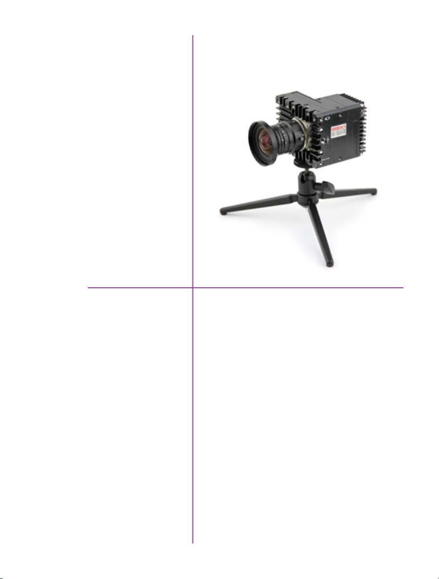
The Miro C110 has a C-mount and a sensor with small,
densely packed pixels to capture detail. Its small size of
72mm x 93mm x 82.5mm and light weight of 0.54 kg
make it easy to mount in tight places and on microscopes.
It uses standard Ethernet and BNC cables.
1
Chapter 1: Introduction
Page 8

Image Storage
The Miro C110 is available with 8GB of internal highspeed memory.
Sensor Characteristics
Advanced Features
The Miro C110 uses a CMOS sensor available in color or
monochrome.
The 5.6 micron (μm) pixels provide a sensitivity, measured
using the ISO 12232 SAT method, of ISO 5,000T; 2,500D
for monochrome cameras, and 640T; 640D for color
cameras (adjustable).
Each pixel has a bit-depth of 12-bits yielding 4,095 gray
levels with high dynamic range.
Sensor resolution is 1280 x 1024 pixels “wide-screen”
format. The rectangular shape of the 1.3 Mpx sensor
allows the user to keep moving objects in the frame
longer and is compatible in aspect ratio with modern
display technology. The physical size of the sensor is
7.168 mm x 5.7344 mm (9.18mm diagonal).
The camera has a global electronic shutter, with
minimum exposure time of 5μs.
Multi-Cine: The internal memory of the Miro C110 can
be partitioned into as many as 63 segments for shorter
recordings, back-to-back, without missing any action.
Image-Based Auto-Trigger (IBAT): The Miro C110 can
detect changes in an image which can be used to trigger
the camera (or even a number of cameras), making it easy
to record unpredictable events.
2
Phantom Miro C110 Camera Manual
Continuous Recording: Automatically save cines from
internal camera memory to external storage, without user
intervention.
Memory Gate: An input signal which, when activated,
prevents the storage of the sensor produced image-data,
by disabling write-access to memory.
Event Marking: Primarily used to tag events of significance
during recording, to make it easier to jump from one event
to the next during playback, along with easing the process
of performing timing measurements of a recorded Cine.
Page 9

Lensing
The Miro C110 has a C-lens mount that can be reversed
to accept CS lenses.
Command & Control
The camera is controlled with Phantom PCC software or a
handheld Phantom Remote Control Unit (RCU).
Detailed information about Phantom cameras,
features, and software can be found at:
www.phantomhighspeed.com
Chapter 1: Introduction
3
Page 10
A
B
C
D
FE
camera connectors
4
Phantom Miro C110 Camera Manual
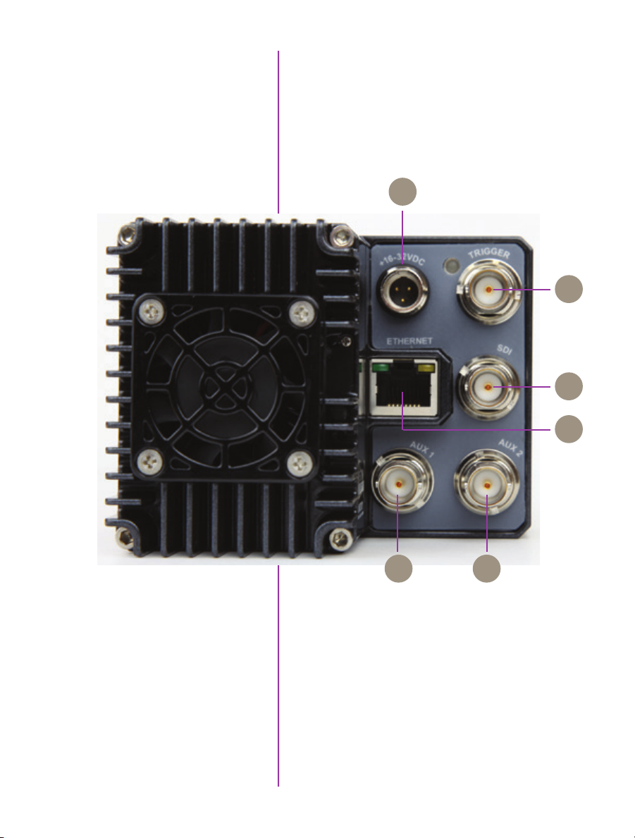
Miro C110 Rear View
Page 11

2
Connectors
+16-28VDC
Trigger
SDI
Ethernet
AUX 1
Mini XLR connector connects to +16-28VDC Power
A
Supply.
Input: when a TTL pulse (rising / falling edge) is
B
detected, camera triggers.
BNC connector for HD video.
C
RJ45 connector connects GigE to a control unit
D
computer / laptop for camera control communication.
Input / Output (switchable via PCC):
E
• Default setting:
- F-Sync (input / output): Connect an external
source, including the F-Sync from a second
Phantom camera, to drive the camera’s frame rate.
Use in combination with Sync; External in
the External Sync menu.
• Available through drop-down box in PCC:
- Strobe (input): Signal goes low for the duration of
each frame’s exposure
- Event (input): When the Event signal is active,
frames are tagged with an Event marker (as
metadata). These events can be searched or
referenced during playback.
- Memgate (input): When Memgate signal is
active the camera stops recording into its internal
memory (frames are discarded).
AUX 2
Input / Output (switchable via PCC):
F
• Default setting:
- Strobe (Output): Signal goes low for the duration of
each frame’s exposure.
• Available through drop-down box in PCC:
- READY (output): When signal is high it indicates
that the camera is in capture mode. Using PCC,
signal can be set to go low at trigger or at the end
of recording.
5
Chapter 2: Connectors
Page 12

6
Phantom Miro C110 Camera Manual
Page 13

3
Quick Start Guide
Prepare Your Computer
Install PCC Software
Cable the Camera
Select Camera for Use
Camera controlling computers:
1. Must have either the Microsoft Windows 7, 8.1, or 10
operating system installed.
2. Firewalls must be turned off.
(Contact your IT Group if necessary)
3. Using the ‘Windows Control Panel’ set the IP address
of your computer’s network card to 100.100.100.1
with a 255.255.0.0 subnet mask.
Install the latest version of Phantom Camera Control (PCC)
software from the accompanying CD or USB key.
Connect the 16-28VDC power supply to the camera’s
power connector.
Attach the supplied Ethernet cable (or any Ethernet cable)
between the Phantom camera and the computer.
If an external trigger is being used to trigger the camera,
connect it to the Trigger BNC on the back of the camera.
In the Manager Control Panel double mouse-click on the
Phantom camera to be used from the ‘Cameras’ group
folder.
Define Recording
Parameters
Click the ‘Live’ tab.
Click ‘Cine Settings’ and define the following parameters
by either the selecting the required value from the pulldown selection list, or typing the value into the respective
data entry field.
1. Set ‘Resolution’ to the required Width x Height.
2. Choose the required ‘Sample Rate’ and ‘Exposure
Time’.
7
Chapter 3: Quick Start Guide
Page 14
3. Post Trigger to zero (0) by:
a. Moving the ‘T’ (Trigger Position) slider to the
right, or
b. Enter zero (0) into the ‘Last’ data entry field.
Perform CSR
Perform White Balance
(Color Cameras Only)
‘Arm’ Camera
Trigger
Edit Cine
Cover the camera lens first, then select the CSR,
(Current Session Reference), button.
Place a white or neutral non-saturated object in front
of the camera and right-click on the white or neutral
non-saturated area in the displayed image, then
Select ‘White Balance’ from the popup display window.
Click the ‘Capture’ button to start recording to the
camera’s internal memory (circular buffer).
At the end of the action, click the action ‘Trigger’ button
at the bottom of the ‘Live’ panel, or
Provide a switch closure or an external trigger signal
(TTL pulse) via the Trigger connector.
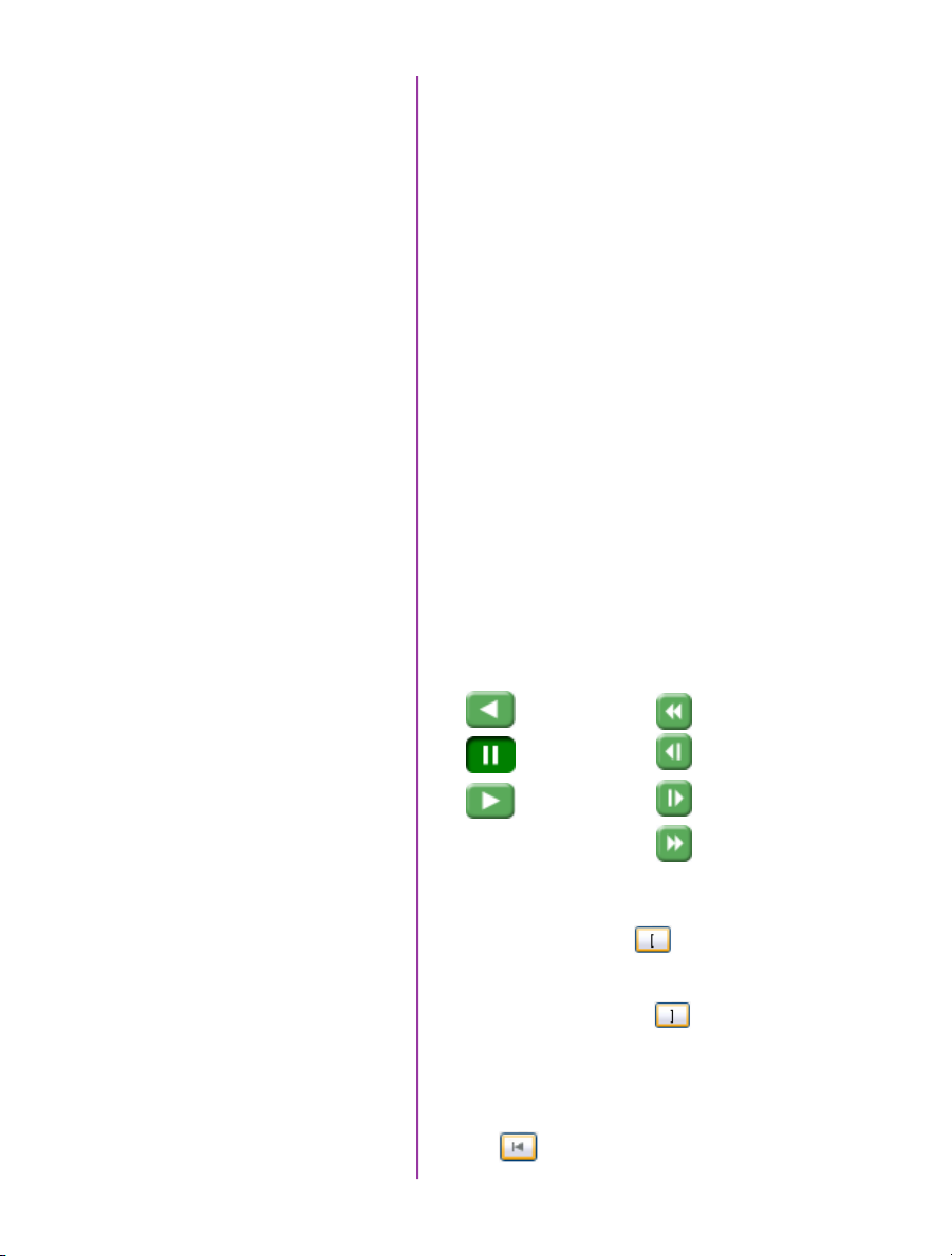
Click the ‘Play’ tab.
Using the following Video Control Buttons to locate the
first image of the cine to be saved.
Rewind
Pause
Play
Fast Rewind
Rewind 1 Frame
Advance 1 Frame
8
Phantom Miro C110 Camera Manual
Fast Forward
Locate the first image of the cine to be saved.
Click the ‘Mark-In button.
Locate the last image of the cine to be saved.
Click the ‘Mark-Out’ button.
Select ‘Play, Speed, & Options’ and enable (check) ‘Limit
to Range’.
Under the Video Control Buttons click the ‘Jump to Start’
button.
Page 15

Review Edited Cine
Review the edited cine using the Video Control Buttons.
Click the ‘Save Cine...’ button at the bottom of the ‘Play’
panel.
Save to Computer
Confirm Computer Save
In the ‘Save Cine’ window:
1. Navigate to the folder where you want to save the
cine file.
2. Enter a file name for the cine file in the ‘File name:’
data entry field.
3. From the Save as type pull-down selection list select
the ‘Cine Raw, *.cine’ file format.
4. Click the Save button to begin downloading the cine
file from the camera to the computer’s hard drive.
Click the down-arrow of the ‘Save Cine... button.
Confirm cine save before deleting from internal
memory
Click the ‘Open File’ button.
In the ‘Open Cine’ window:
1. Navigate to the folder containing the saved cine file.
2. Highlight the cine file to be opened.
3. Click the Open button.
Using the Video Control Buttons review the saved cine file.
Chapter 3: Quick Start Guide
9
Page 16

10
Phantom Miro C110 Camera Manual
Page 17

4
Phantom Software
The latest version of Phantom PCC software
can be found and downloaded from the support
section of the Vision Research website:
www.phantomhighspeed.com
Pre-Installation
pcc software
PCC (Phantom Camera Control)
Application Overview
Toolbar
Phantom control software is certified to operate with
the following Microsoft Windows operating systems:
Windows 7, 8.1 and 10.
The computer and camera must be associated with the
same sub-network to communicate with one another.
Vision Research has preset IP address (100.100.x.x)
with a subnet mask (255.255.0.0) to the camera.
Typically the IP address 100.100.100.1 / 255.255.0.0 is
defined to the control computer. When multiple computers
are used to control the same camera, each computer
requires a unique IP address, for example, 100.100.100.1
(255.255.0.0), 100.100.100.2 (255.255.0.0), and so on.
The software is built around a multi-layered work area that
includes the following work areas:
Provides quick access to the most frequently used
functions. Position the mouse over a button and wait for a
second to display a text box describing what it is.
Note the ‘Help’ buttons which provides valuable reference
information on the software, including extensive documentation.
Chapter 4: Control via Phantom Software
11
Page 18

Control Tabs
The main window of PCC is divided into three tabs: Live,
Play and Manager.
When first started, the ‘Manager’ tab is selected. It is in
this tab connected cameras are displayed, selected for
use, and renamed. It is also used to manage saved Cine
files.
To rename, highlight then click the name of a camera.
This can be useful when working with multiple cameras.
All camera control and setting of shooting parameters
(frame rate, shutter, etc.) is performed in the ‘Live’ tab.
The ‘Play’ tab is used to review, edit, and save Cine files,
(either from the camera or from files on the local hard
drive).
PVP (Phantom Video Player)
Application Overview
12
Phantom Miro C110 Camera Manual
PVP can be launched directly from the desktop, or by
clicking the ‘Video Out’ toolbar button in PCC. PVP
controls only the camera’s HD-SDI outputs as connected
to a compatible SDI monitor.
PVP provides the ability to view, capture, review, edit,
and/or save a Cine recorded into the camera’s RAM to a
hard drive.
Page 19

Camera Control via PCC
PCC provides the ability to select various units for specific
camera parameters by clicking the ‘Preference’ button at
the bottom of the Manager tab.
Units can be set to commonly used values (‘Presets’) or
they can be customized using the pull-down selection
lists. First time users should use one of the three ‘Presets’.
The ‘Exp’ unit is probably the most important unit to be
set. It specifies what unit to use when setting the exposure
time. You probably will want this set to micro-seconds. The
other unit to set is PTF (Post Trigger Frames) covered later
in this section.
Double-click the camera(s) to be controlled listed in the
‘Manager’ tab, or select the camera(s) from the ‘Camera’
pull-down list in the ‘Live’ tab.
13
Chapter 4: Control via Phantom Software
Page 20

Image Processing
Once a camera is selected a ‘Preview’ panel will display
to the left of the control tabs showing the current image
being captured by the camera. This image may
differ slightly to that of the image being output over
the camera’s SDI port due to display differences in the
video monitor and computer screens.
You can adjust the display options by clicking on the
‘Image Tools’ toolbar button.
The ‘Image Tools’ window is used to view a ‘Histogram’
and change settings that affect the computer display and
the video output of the camera.
Some of the variables include; brightness, gain, gamma,
saturation, hue, white balance adjustments (Temp (K) and
Tint), individual red, green and blue pedestal, gain and
gamma values, tone control, and more.
When Log mode is selected, most of these variables are
locked and can not be adjusted.
At the bottom of the window is a ‘Default’ button that
restores all parameters except white balance, tone, and
color matrix to their default values.
14
Phantom Miro C110 Camera Manual
The ‘Default White Balance’ button restores white balance
to the default (which under the most typical lighting will
produce a green image).
The Tone ‘Reset’ button restores the image tone to the
default values, and the Color Matrix ‘Restore’ button return
the color matrix values to their default values.
Changes made only affect the metadata of the
Cine file, not the raw data. If you are recording
the camera’s video output it is important that
these be set to values that produce the image
you wish to record.
The ‘Zoom Actual Size’ toolbar button resizes the images
being displayed in the Preview/Playback panel to their
actual size.
Page 21

The ‘Zoom Fit’ toolbar button resizes the images to fit
panel.
Images can also be zoomed to a specific magnification
ratio by selecting a number from the pull-down list to the
right of the Zoom Fit button.
Automatic White Balance
Performing a White Balance should be the first step in
color adjustment (color cameras only).
Right mouse click on area that resembles white in the
image in the ‘Preview’ or Playback’ panel, then click on
the ‘White Balance’ pop-up window. It is not necessary to
fill the frame with white – a small target can be used.
Capture Settings
Just below the ‘Camera’ selector in the ‘Live’ tab are a
series of expandable headers, which contain groups of
related camera settings.
This manual will cover the most commonly used
settings, see the ‘Pcc Help’ file for details of
other settings.
15
Chapter 4: Control via Phantom Software
Page 22

Camera Settings
& Cine Settings
Camera Settings are used to set
and recall the overall camera
system parameters. Cine
Settings are used to set the
capture parameters.
Set Time: Synchronizes the time stamps embedded in the
recorded image data to the computer’s clock.
Bit Depth: The Miro C110 operates in 12-bit mode only.
Partitions: Select the number of desired partitions (evenly
divided memory segments) from the ‘Partitions’ pull-down
menu. For basic camera setups, this should be set to one.
Lens Control: Not supported by the Miro C-Series
cameras.
Backup & Restore: Allows for user settings to be saved
and recalled from the camera’s memory.
Resolution: Set the the number of pixels used to capture
an image. For example, if 1280 x 1024 (width x height) is
set, the full sensor space is available. Smaller resolutions
allow higher recording speeds. Cropped resolutions are
set using the ‘Crop and Resample’ menu in Image Tools.
Sample Rate: Set the acquisition frame rate in framesper-second (FPS).
Exposure Time (shutter): Set the exposure time in microseconds, percentage, or degrees (this depends on how the
PCC preferences are set).
16
Phantom Miro C110 Camera Manual
EDR (Extreme Dynamic Range): Not supported.
Exposure index: This is a reference display of the EI value
in relation to the Image settings.
CSR (Current Session Reference): With the lens covered
performing a CSR resets the black point of every pixel for
optimal image quality.
Image Range and Trigger Position: The slider represents
the memory buffer, with the ‘Duration’ indicated in
seconds and the total number of frames available.
Page 23

The trigger position is indicated in the ‘Last’ pull-down
menu or as the ‘T’ slider along the timeline. The trigger
position is the point at which the camera stops continually
recording when a trigger signal is detected.
Key Advanced Settings
The first of these key features is the option to enable
the ‘Start/End of recording actions’ to be performed
automatically at the beginning or end of a shot. The most
common ones are:
• ‘Auto play Video Out’ begins playback after record-
ing. The range marked under ‘Auto play Video Out’
affects both playback and saving to the internal
CineFlash.
• ‘Restart Recording,’ when enabled, automatically
restarts the recording process after the ‘Auto’
actions have been performed.
When ‘Restart Recording’ is enabled PCC does
not provide any user confirmation before the clip
is erased from RAM and starts recording again.
This feature should be used with care!
‘External Sync’ instructs the camera to utilize one of the
following three frame sync clock sources:
• Internal - instructs the camera to utilize its’ internal
crystal oscillator to drive the camera’s frame rate.
• External - should be selected when an externally
supplied frame sync clock pulse is supplied to drive
the frame rate. This can be used to synchronize two
cameras together via F-Sync.
• LockToVideo - Frame rate is driven by the camera’s
current video rate. FPS will jump to the closest
multiple of the current video rate (23.98, 24, 25,
29.97 or 30).
Recording a Cine
In ‘Loop’ mode to begin recording to the camera’s RAM
click the red ‘Capture’ button.
17
Chapter 4: Control via Phantom Software
Page 24

The red ‘Capture’ button changes to ‘Abort Recording’ and
the green ‘Trigger’ button is enabled when the camera is
recording. The Abort Recording button instructs the
camera to stop recording, leaving the camera’s RAM
empty.
Triggering the Camera
Reviewing a Cine
Selecting the ‘Trigger’ button instructs the camera to
immediately stop recording when the ‘Trigger Position’ is
set to zero. If a value greater than zero is set, the camera
will continue to record ‘post-trigger’ frames until the user
specified value is met.
Using an external trigger signal provides a more accurate
trigger to the camera.
If a clip exists in the camera’s memory, you will
be asked if you are sure you wish to delete it
before continuing. If yes, click ‘Delete cine(s) and
start new recording’.
Once the camera has completed recording a Cine in the
camera’s RAM it can be reviewed by selecting it from the
‘Cine’ pull-down selection list in the PCC ‘Play’ tab.
A previously saved Cine stored on the computer’s
hard drive can be opened using the ‘Open File’
toolbar button (also places the file under the
‘Cines’ group folder in the Manager tab).
The viewing option can be changed via the ‘Play Speed
& Options’ and the Cines’ metadata can be viewed in the
‘Frame Info’ and ‘Cine Info’ sections.
18
Phantom Miro C110 Camera Manual
Page 25

A B C
D E F G
Use the ‘Video Control’ buttons to review the cine.
A. Rewind
B. Pause
C. Play
D. Fast Rewind
E. Rewind 1-Frame
F. Advance 1-Frame
G. Fast Forward
Performing a Quick Search
Through a Cine
Editing a Cine
Quickly search through cine files to find the points of
interest:
‘Scroll’ (scrub) through the clip using the ‘Image Location’
slider or click anywhere on the timeline to jump to points
in the cine quickly.
‘Jump’ to the trigger frame by clicking on the ‘T’ button,
or jump to specific frames by entering the frame number
into the jump ‘#’ data entry field, then hit the enter key.
‘Image Search’. The goal is to search or find an image
change in the recording, based on the difference between
image content. Right-Click on the ‘Play’ button to begin
the image search. Besides image content changes, Image
Search can also look for images that are tagged as ‘Event’
images.
Using the following ‘Video Control’ buttons locate the first
image of the cine to be saved and click the ‘Mark-In’
button.
Locate the last image of the cine to be saved and click the
‘Mark-Out’ button.
Click ‘Play, Speed, & Option’ and enable (check) ‘Limit to
Range’.
Saving a Cine
Under the ‘Video Control’ buttons click the ‘Jump to Start’
button, then review the edited cine.
Click the ‘Save Cine...’ button to save the edited cine to
the computer’s hard drive.
19
Chapter 4: Control via Phantom Software
Page 26

20
Phantom Miro C110 Camera Manual
Page 27

Download &
5
Introduction
PCC Software Solutions
Converting Cine Files
Image Processing
The images recorded on the camera’s RAM are stored in
a Vision Research proprietary RAW (uncompressed) file
structure called a ‘Cine’ file.
These Cine files can be converted to industry standard
formats (ProRes, H264, DPX, DNG, TIFF, JPEG, and more)
with PCC software provided by Vision Research. Phantom
PCC and PVP software are only compatible with Windows
operating systems, however there are third party solutions
available for working with Phantom cameras in Mac OSX.
Windows-based PCC software provides the ability to
convert cine files into a number of other formats.
Single cine files can be converted by selecting the desired
format from the ‘Save as Type’ selection list in the ‘Save
Cine’ dialogue window.
The file formats above the separator line in the ‘Save as
Type’ selection list are ‘movie-like’ formats (meaning the
entire clip will be saved as a single file) while the formats
below the line are image formats (meaning each frame of
cine will be saved as a sequence of images).
Re-saving a clip in the ‘Cine RAW’ format can
be useful for creating sub-clips with no loss in
image quality or metadata.
To convert a cine to a ‘movie-like’ format select the
desired format from the list, navigate to the destination
folder, assign a file name to the clip and save.
Some valuable parameters can be found in the ‘advanced
settings’ window, such as the particular codec.
Other formats, like .avi and .mp4 allow the compression
ratio to be entered. The lowest compression is the default.
Chapter 5: Download & Image Processing
21
Page 28

To convert a cine clip into a sequence of images (frames)
you must add one of the following annotations to the
end of the file name: ‘!n’ or ‘+n (where n is the number
between 1 to 8). This will assign the sequential frame
numbers to the file name for each frame being created.
Example: image_!5.tif
The ‘!’ annotator instructs the software to append the
cine’s image number (relative to the trigger point) to
the file name. If the first frame in the clip is - 100,
then the first converted frame will have the name:
image_-00100.tif.
The ‘+’ annotator will add frame numbers starting at 1.
Example: image_+5.tif
This will cause the first converted frame to have the name:
image_00001.tif
Ensure all image adjustments have been applied
prior to initiating the conversion process. All
metadata (gain, gamma, saturation, etc.) will
be embedded into the converted images.
22
Phantom Miro C110 Camera Manual
Batch Convert
The ‘Batch Convert Files’ toolbar button can be used to
convert a single, or multiple saved cine files into any one
of the supported file formats.
Use the shift and/or control keys, to select the cine files
you wish to convert in the ‘Open Cine’ dialogue window,
then click the ‘Open’ button.
Navigate to the destination folder, in the ‘Multifile Convert
Destination’ dialogue window, and select the file format.
The ‘File Name’ will depend on the type of file format you
are converting to.
If you are converting the cine file into a ‘movie-like’
formats leave the file name as ‘All selected file.’ The
software automatically assigns the original file name
to the converted file and appends the appropriate file
extension.
Page 29

However, if you are converting the file into a sequence of
images, you need to enter the annotation only detailed in
the ‘Convert a Cine’ topic earlier in this chapter.
Example: +4
The software automatically creates a separate folder for
each of the files being converted, assigns the original file
name, and appends the appropriate image number and
file extension to each image.
Once the ‘Convert’ button is clicked a progress window
appears. Each converted cine will be placed in its own
folder named after the original cine file.
23
Chapter 5: Download & Image Processing
Page 30

Example of three points being tracked. The graph plots and displays, by default, the x-axis coordinate
of all points / targets from the Origin point.
24
Phantom Miro C110 Camera Manual
Page 31

6
Measurements
Introduction
Data Acquisition
With the PCC (Phantom Camera Control) 2-D motion
analysis tools, the end-user can perform timing,
position, distance, velocity, angle and angular speed
measurements, and track multiple points or objects to
compute and graph their XY-coordinates, speed, or
acceleration. PCC, for example, provides several edge
detection algorithms and image processing tools to
improve the measurement process. The measurement
technology provides a motion analysis system that
harmonizes measured data with images.
Details on how to use the various PCC
measurement tools can be found in the PCC
Help File > Step-by-Step Procedures >
Play Panel Procedures > Measurements.
To investigate the effect environmental conditions may
have on the recorded data, a National Instruments™
USB- or M- Series Data Acquisition (DAQ) module
can also be used to acquire data from a wide range of
sensors, and synchronize it with slow-motion video images
recorded on a Phantom camera, using Phantom Camera
Control (PCC) software.
Chapter 6: Measurements
25
Page 32

mechanical drawings
26
Phantom Miro C110 Camera Manual
Top View
Bottom View
Page 33

7
Support
Front View
Rear View
27
Chapter 7: Support
Page 34

Right View
Left View
28
Phantom Miro C110 Camera Manual
Page 35

Use these schematics to build custom cables at your own risk. Mis-wired cables
can cause serious damage to the camera, which is not covered under warranty.
Vision Research recommends only using cables supplied by Vision Research.
These pin-out diagrams refer to the connector on the camera body. Part numbers
indicated are for the cable’s connector.
Power Connector
Power port
3-pin Mini XLR Connector part # REAN RT3FC-B
PIN NOMENCLATURE / FUNCTION
1 GND / Power Ground
2 VDC / Provides DC (Direct Current) positive power to the
Phantom camera. Valid voltage ranges are +12-28VDC
3 CHGND / Chassis Ground
Ethernet Connector
Gigabit Ethernet port
RJ-45
PIN NOMENCLATURE / FUNCTION
1 MDI2+ / Gigabit Ethernet
2 MDI2- / Gigabit Ethernet
3 MDI3+ / Gigabit Ethernet
4 MDI3- / Gigabit Ethernet
connector pinouts
5 MDI1+ / Gigabit Ethernet
6 MDI1- / Gigabit Ethernet
7 MDI0+ / Gigabit Ethernet
8 MDI0- / Gigabit Ethernet
29
Chapter 7: Support
Page 36

BNC Connectors
Multiple signal ports
BNC
Description
Trigger Input: when a TTL pulse (rising / falling edge) is
detected, camera triggers.
SDI Output: for HD video.
Aux 1 Input / Output: switchable via PCC:
• Default setting:
- F-Sync (input / output): Connect an
external source, including the F-Sync from
a second Phantom camera, to drive the
camera’s frame rate. Use in combination
with Sync; External in the External Sync
menu.
• Available through drop-down box in PCC:
- Strobe (input): Signal goes low for the
duration of each frame’s exposure.
- Event (input): When the Event signal is
active, frames are tagged with an Event
marker (as metadata). These events can
be searched or referenced during
playback.
- Memgate (input): When Memgate signal
is active the camera stops recording into
its internal memory (frames are discarded).
Aux 2 Input / Output: switchable via PCC:
• Default setting:
- Strobe (Output): Signal goes low for the
duration of each frame’s exposure.
• Available through drop-down box in PCC:
- READY (output): When signal is high it
indicates that the camera is in capture
mode. Using PCC, signal can be set to go
low at trigger or at the end of recording.
30
Phantom Miro C110 Camera Manual
Page 37

A
B
Miro C110 Rear View
Trigger LED
A
led indicators
Ethernet LEDs
B
COLOR CAMERA STATE
White Camera is booting up
Green Camera is in Preview mode
Red Camera is in Capture mode
Red Flashing Camera is in Trigger mode, and saving images
COLOR ETHERNET STATE
Green Ethernet Link
Amber Ethernet Activity
31
Chapter 7: Support
Page 38

What are the recording
limits of a Miro C110?
faqs
1
Determined by ‘Resolution’
(Height) setting
Resolution (W x H)
1280 x 1024
1280 x 720
1024 x 768
768 x 576
768 x 480
512 x 512
512 x 384
512 x 320
384 x 288
256 x 256
128 x 128
128 x 64
128 x 16
128 x 8
Max FPS
915
1295
1215
1615
1935
1815
2405
2870
3180
3565
6870
12805
36365
52445
1
Can I use any Ethernet cable
with the Miro C110?
Can I use my F-mount lens with
the Miro C-Series cameras?
The C110 looks like the C210.
Is it Hi-G? Can it be used with a
Miro Junction Box?
If the camera doesn’t have a
shutter, how can I perform a
Current Session Reference?
What are the available
signals for the C110?
What is the worst case power
draw of the cameras?
32
Phantom Miro C110 Camera Manual
Yes. We include an Ethernet cable and a BNC cable with
the camera, just to get you started. But any Ethernet or
BNC cable will work.
Yes, with a converter. The Miro C’s come with a C lens
mount that can be reversed to become a CS lens mount.
To use an F-mount lens, you can purchase a converter
(part number VRI-FMNT-CMNT).
The Miro C110 has many of the design features as the
C210, and it is made to be rather tough. However, it is not
specified as a Hi-G camera, and cannot survive the same
shocks and vibrations that the C210 can survive. The
C110 is not designed to work with a Miro Junction Box,
and has different connectors.
The Miro C’s do not have a shutter, but you can still
perform a Current Session Reference (CSR). Just make
sure you cover the lens before clicking the CSR button.
Trigger (dedicated BNC); SDI (dedicated BNC); F-Sync
(Aux 1 default); Strobe (Aux 2 default)
The cameras draw only 12W during operation.
Page 39

There are fixed black
spots on the image,
particularly at
small apertures.
This is most likely caused by dust particles stuck on the
sensor or OLPF (optical low pass filter) surface. The best
way to check is to remove the lens and look at the glass
surface with a bright light source. Vision Research
recommends not to use canned air or cotton swabs to
clean the sensor surface. It is safer to use a manual
bulb-style air blower and/or sensor cleaning brush for
removing loose dust particles.
Additional tips for cleaning sensors can be found in the
maintenance section of this manual.
The live images look
scrambled and the frame
rate can’t be set.
Restoring the factory
defaults
Back Focus Adjustment
If the image is non-responsive and scrambled, the camera
may be set to an external sync without a sync source
connected. In the PCC > Live > Advanced Settings menu,
check the External Sync setting to ensure that ‘Internal’
is selected.
If the camera is stuck in an unusual state it may be useful
to restore the camera’s factory defaults. This returns the
capture parameters, image processing, video modes, and
image calibration back to the original settings.
To do this, you will need to perform an ‘iLoad’. For
details on performing an ‘iload’ follow the ‘Step-by-Step
Procedures / Live Panel Procedures / Advanced Settings /
Performing an iLoad (on a Ph16 Camera)’ topic within the
supplied PCC Help file.
Due to differences in various lenses and other mechanical
tolerances it may be necessary to adjust the lens mount
on the camera to obtain proper focus. In most cases,
changing a lens or replacing a mount will not require
adjusting the back focus, though it should be verified.
When the focus distance marks on a lens do not match
the measured distance between the sensor & subject,
it indicates the need to adjust the back focus.
By adjusting the back focus, you are changing the
distance of between the flange and the sensor plane.
basic troubleshooting
Shims are included to assist in both slight and coarse
back focus adjustments.
33
Chapter 7: Support
Page 40

Sensor & OLPF Cleaning
Technical Tips
• Sensor cleaning should only be attempted by
experienced imaging professionals.
• Use a small, but powerful flashlight to look at the
sensor and filter, it’s easier to spot the dust.
• The OLPF assembly is removable and located in front
of the sensor. Once the lens mount is uninstalled the
OLPF can be easily removed (2 screws) for cleaning
(if applicable).
• Sensor cleaning must be done in a clean and con-
trolled environment.
• Always have a forced-air bulb style blower and a
clean sensor cloth handy for more serious dirt.
• Sensor cleaning solution (like Eclipse) should only be
used if absolutely necessary, and applied with a soft
wipe intended for sensor cleaning.
• Cotton swabs aren’t a good idea, unless they are
wrapped in a sensor wipe material. They leave
behind more than they remove.
maintenance
• Never use your finger to get a speck of dust off, it’s
going to make things much worse.
34
Phantom Miro C110 Camera Manual
• Never blow on the sensor or OLPF.
• Never put sharp objects near the surface of the OLPF
or sensor.
• Always keep the Phantom body cap on the camera
when there is no lens attached.
Page 41

Global Headquarters
support
Vision Research, Inc. - Wayne, New Jersey
100 Dey Road
Wayne, New Jersey 07470 USA
T: +1.973.696.4500
F: +1.973.696.0560
For answers to most questions, please visit us at:
www.phantomhighspeed.com
For general product, account, order / RMA status inquires
and other non-technical questions please e-mail us at:
customer.support@visionresearch.com
For technical product support, product operation or
applications support please e-mail us at:
technical.support@visionresearch.com
Live Customer and
Technical Support
Serving the Americas:
M-F 8:00 AM to 5:00 PM EST (GMT-4:00)
Vision Research, Inc. - Wayne, New Jersey
T: +1.973.696.4500
F: +1.973.696.0560
Customer Support, extension 4002
Technical Support, extension 4003
Serving Europe, the Middle East and Africa:
M-F 9:00 AM to 6:00 PM GMT +3:00
Vision Research, Inc. - Bucharest, Romania
T: +40 21 210 8587
F: +40 21 210 8587
Serving Asia Pacific:
M-F 8:00 AM to 5:00 PM GMT +8:00
Vision Research, Inc. - Shanghai, China
T: 86-21- 58685111, ext:141
35
Chapter 7: Support
Page 42

36
Phantom Miro C110 Camera Manual
Page 43

Page 44

Vision Research - Corporate Headquarters
100 Dey Road
Wayne, New Jersey 07470
USA
Ph: +1.973.696.4500
Toll Free: 800.737.6588
Fax: +1.973.696.0560
Vision Research Ltd. - UK
Suite F8, Bedford i-lab
Priory Business Park
Stannard Way, Bedford
MK44 3RZ, United Kingdom
Ph: +44 1234 834 850
Fax: +44 1234 834 851
w w w . p h a n t o m h i g h s p e e d . c o m
PN: ZDOC-64078-MA-0003 Rev 3
Last Updated: 27.FEB.2017
 Loading...