

Page 1
PWM HUB
PACKAGE CONTENTS
INSTALLATION GUIDE
4-pin to 4-pin
(to motherboard CPU_Fan)
FAN HUB
QTY: 1
Description:
4-PIN TO 4-PIN CABLE
QTY: 1
Description:
2-PIN TO SATA CABLE
QTY: 1
Description:
3-pin
(TO PWM HUB: FAN2, FAN3, FAN4, FAN5, FAN6)
FAN SPLITTER ADAPTER
QTY: 2
Description:
VELCRO MOUNT
QTY: 1
Description:
SCREWS
QTY: 2
Description:
Chassis mounting screws
SATA 12V Power input
(power supply)
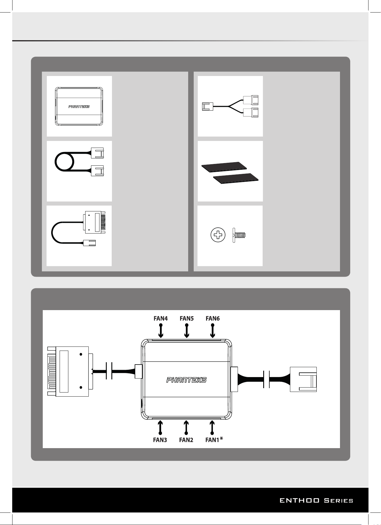
SPECIFICATIONS
SATA 12V POWER INPUT
(Power supply)
CM6 #5
4-pin
(Motherboard CPU_Fan)
see important note
Page 2
INSTALLATION
The PWM hub functions optimally when modulated by a PWM signal from the motherboard, which will allow
the greatest control range. However, not all 4-pin motherboard connectors implement the PWM signal modulation.
Connecting the 4-pin to CPU_FAN
For full PWM functionality, Phanteks’ PWM hub requires users to connect the 4-pin connector to the “CPU_Fan”
connector of the motherboard, because all motherboard manufacturers implements a PWM signal modulation
on this connector. Connect the SATA 12V power to power the PWM hub. Not all motherboards have their CPU_
Fan connector set on PWM signal modulation by default. Please consult your motherboard documentation for
this matter.
Connecting the 4-pin to other 4-pin header (besides the CPU_Fan)
Other 4-pin connectors can be found on modern motherboards besides the “CPU_Fan” connector (e.g. “CPU_
Fan2”, “CHA_Fan”, “OPT_Fan”), however not all motherboard manufacturers implement a true PWM signal modulation onto these connectors. These type of 4-pin connectors modulate the RPM by voltage, which has a smaller
control range compared to modulation by true PWM signal.
The 12V SATA power cable can not be used to power the PWM hub if connecting to these types of 4-pin connectors, due to the interference with the RPM regulation by voltage (resulting in the fans running on full RPM). The
PWM hub will draw its power from the 4-pin connector, which is limited to a total device consuming 30W in total.
Important Note:
1 motherboard connector can only read 1 RPM signal. Therefore, the motherboard will only read the RPM signal from 1
device connected to Fan 1. The RPM form all other devices will be regulated according to FAN 1. Y-splitter should not be
connected to FAN 1.
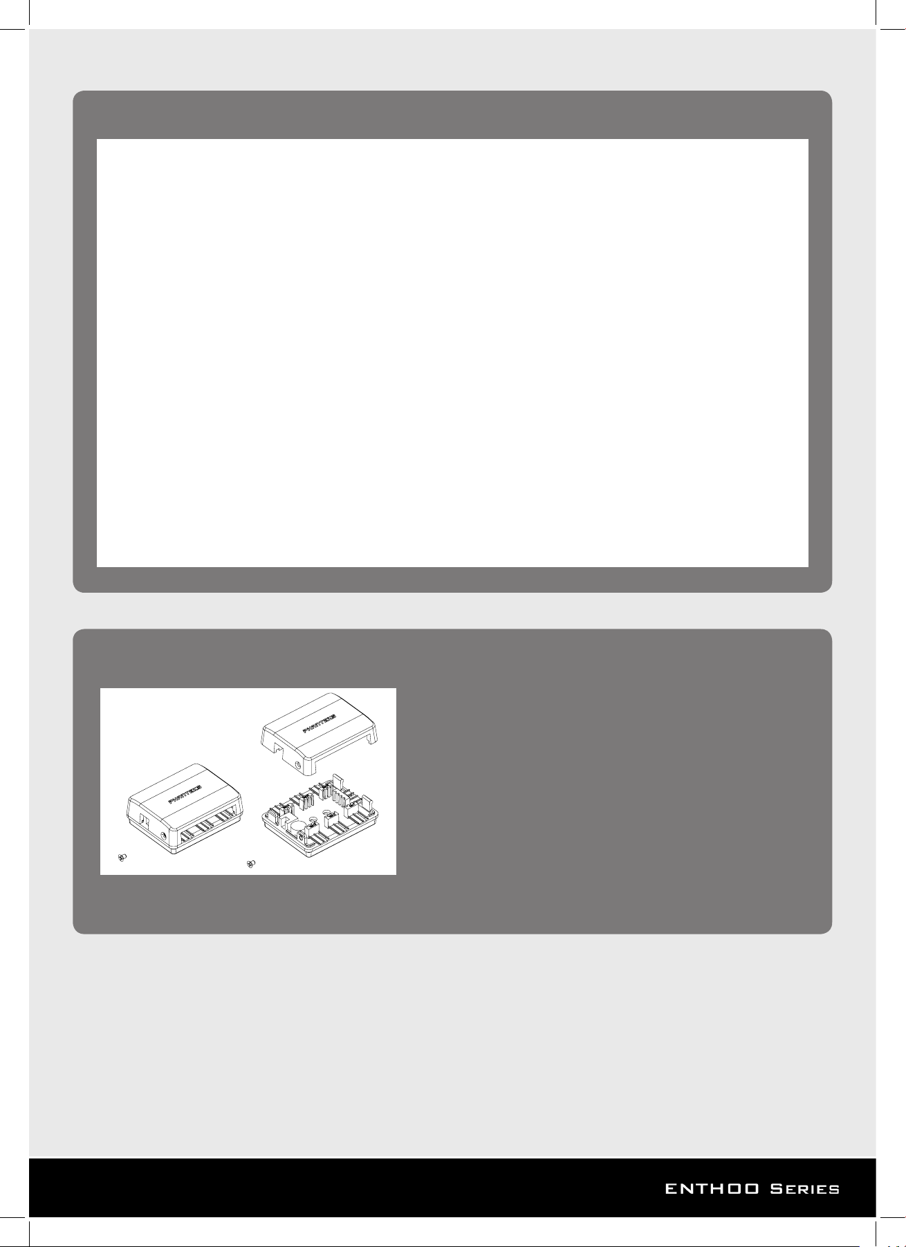
INSTALLATION
1. Installing in Phanteks’ case:
Step 1. Unscrew the side screw to open top cover.
Step 2. Place the pwm board (without top cover) onto the mounting area of the Phanteks chassis.
Step 3. Screw in the 2 included screws
Step 4. close the top cover and screw in the side screw.
2. Installing in universal case:
*Make sure the pwm hub will t in the mounting area (18mm clearance)
Step 1: Stick 1 of the velcro sheet on the PWM hub bottom.
Step 2: Stick the other velcro sheet on the desired installation area in the chassis.
Step 3: Place the PWM hub onto the velcro sheet.
SERVICE AND SUPPORT
If you have any questions or concerns, please visit Phanteks’ website for technical support. We consider customer support, satisfaction and feedback an
essential element of our overall marketing eort. Please feel free to contact our support team. Thank you!
Contact Us at:
www.phanteks.com
www.phanteksusa.com
www.phanteks.cn
For Warranty Information, please visit Phanteks’ website.
 Loading...