

Page 1
ECLIPSE P350X / P360X
INSTALLATION GUIDE V1.0
INTRODUCTION INCLUDED ACCESSORIES
Thank you for choosing Phanteks. Please take a moment
to carefully go through the manual. Phanteks will not take
responsibility for any damages incurred due to incorrect
installation or usage of this product.
Eclipse P350X Eclipse P360X
PRODUCT OVERVIEW
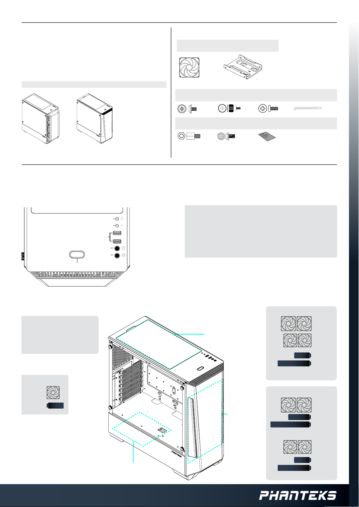
ECLIPSE P350X / P360X FRONT I/O
2. Headphone
3. Microphone
4. USB 3.0
5. D-RGB Color
6. D-RGB Mode
1. Power Button
English
1. Power Button
2. Headphone
3. Microphone
4. USB 3.0
5. D-RGB Color
6. D-RGB Mode
120 mm Case Fan
(Pre-Installed)
22x Motherboard
+ SSD Screw
1x MotherboardStando
Francais
1. Bouton d’alimentation
2. Casque
3. Microphone
4. USB 3.0
5. D-RGB Couleur
6. D-RGB Mode
2.5” SSD Bracket
(Pre-Installed)
2x Thumb Screw
4x PSU Screw
Deutch
1. Ein-/Austaste
2. Kopfhörer
3. Mikrofon
4. USB 3.0
5. D-RGB Farbe
6. D-RGB Modus
12x Fan Screw
1x This Manual
6x Zip Tie
Espanol
1. Botón de encendido
2. Auricular
3. Micrófono
4. USB 3.0
5. D-RGB Color
6. D-RGB mode
ECLIPSE P350X / P360X FANS & RADIATORS CLEARANCES
CLEARANCE
CPU Cooler Height 160mm
PSU Clearance 250mm
GPU Clearance 400mm
E-ATX Motherboard 280mm
REAR
120
FAN
120
120
RAD
PSU FILTER
TOP FILTER
FRONT FILTER
TOP
140
FAN
120
FAN
120
240
*max motherboard component height is 38mm
FRONT
140
280
Max 142x315mm
120
240
Max 122x315mm
120
RAD
140
FAN
140
RAD
120
FAN
120
RAD
Page 2
ECLIPSE P350X / P360X
INSTALLATION GUIDE V1.0
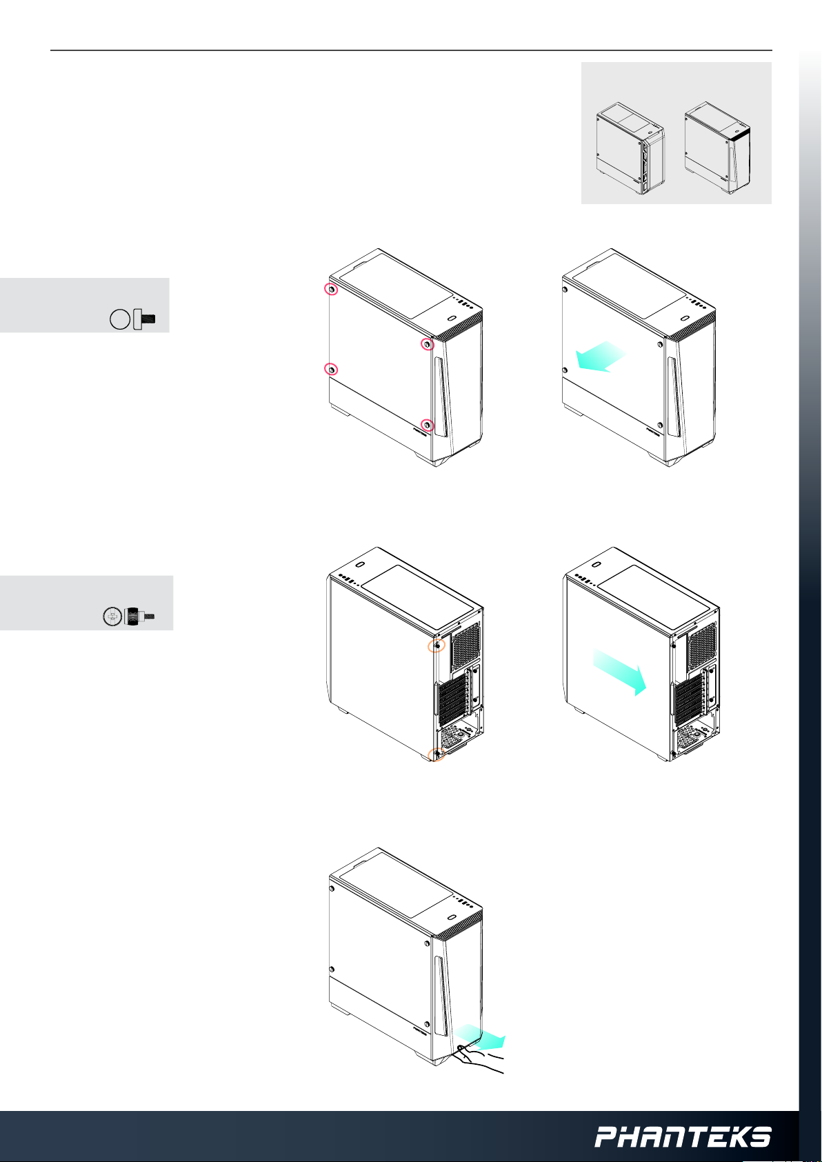
PANEL REMOVAL
There are three panels which can be removed from the P350X and P360X Chassis; the left side
tempered glass panel, the right side panel and the front panel. Follow these steps below.
LEFT SIDE PANEL
REMOVE THUMB SCREWS
1. 1.
REMOVE:
4x
REMOVE TEMPERED GLASS PANEL
2.
Instructions for:
Eclipse P350X / Eclipse P360X
2.
RIGHT SIDE PANEL
LOOSEN THUMB SCREWS
1.
LOOSEN:
2x
SLIDE SIDE PANEL OFF
2.
FRONT PANEL
REMOVE FRONT PANEL BY PULLING ON
1. 1.
THE PANEL FROM BELOW
1.
2.
Page 3

ECLIPSE P350X / P360X
HARDWARE INSTALLATION
MOTHERBOARD
INSTALL THE MOTHERBOARD USING THE MOTHERBOARD SCREWS.
1.
9x
POWER SUPPLY
INSTALL THE POWER SUPPLY WITH 4 PSU SCREWS.
1.
4x
INSTALLATION GUIDE V1.0
2.5” SSD
INSTALL THE SSD WITH 4 SSD SCREWS AND PLACE IT ON THE 4 RUBBER GROMMETS.
1.
4x
3
2
1
3.5” HDD
INSTALL THE HDD IN THE BRACKET AND PLACE IT IN THE CHASSIS.
2.
1
2
The HDD Tray can
also hold a 2.5” SSD.
Page 4

ECLIPSE P350X / P360X
CABLE CONNECTION
INSTALLATION GUIDE V1.0
CONNECT TO DIGITAL-RGB PRODUCTS
TO DIGITAL-RGB PRODUCTS
TO DIGITAL-RGB MOTHERBOARD
Connect to compatible motherboard for
software control. See the below section:
Digital-RGB Control.
OPTIONAL UPGRADES
VERTICAL UPGRADE (PH-VGPUKT_02)
The P350X and P360X supports the Phanteks Vertical GPU bracket.
It can be easily installed in the PCI slot area. Follow the instructions that are included with the Vertical GPU bracket.
CONNECT TO MOTHERBOARD
Power SW
HD
AUDIO
USB 3.0
CONNECT TO POWER SUPPLY
SATA
DIGITAL-RGB CONTROL
With the Integrated Digital-RGB controller, you can choose from a variety of modes and color options.
COLORS
COMPATIBLE WITH:
D-RGB Color
D-RGB Mode
MODES
SOLID
BREATHING
RADAR
SPARKLE
RAINBOW
PRESS AND HOLD THE MODE BUTTON TO TURN OFF FRONT LEDS
2 SEC
PRESS AND HOLD THE MODE BUTTON AGAIN TO TURN OFF ALL LEDS
SOFTWARE CONTROL: Turning o all LED’s will allow
for software control with a compatible motherboard.
The Mode & Color buttons do not function when
using Software Control.
MAXIMUM POWER: The Digital-RGB controller can
provide a maximum of 7A of power for expansion.
 Loading...