

Page 1
M2.5x5, washers
QTY: 20
Glacier G1080 Water Block
(MSI GTX 1080/1070 GAMING)
QTY: 1
Thermal Pads
QTY: 2
Description:
For applying on circuit board on GPU
STEP 1. REMOVING STOCK COOLER
-
WARNING -
body’s static electric charge by touching a grounded surface – for
example, the metal surface of the power supply or chassis – before
performing any hardware procedure. Phanteks assumes no liability
for any damage, caused directly or indirectly, by improper installation
of any components. If you do not feel comfortable with performing
*Please do not disassemble the water block. Warranty will be voided.
Thermal Compound (PH-NDC_01)
QTY: 1
Phanteks Plugs
QTY: 2
TAKE OUT THE TOP EVA-FOAM LAYER FROM THE BOX TO USE AS BASE FOR YOUR GPU PLACEMENT.
Phanteks RGB Cable
QTY: 1
INSTALLATION GUIDE
MSI GAMING
M2.5x5, washers
QTY: 20
Thermal Pads
QTY: 3
Description:
For applying on circuit board on GPU
Phanteks Plugs
QTY: 2
Phanteks RGB Cable for GPU
QTY: 1
INSTALLATION GUIDE
MSI GAMING
Phanteks RGB Cable for Phanteks Case
QTY: 1
13x160x1.5mm (for Vdd MOSFET)
20x120x1.5mm (for memory IC)
10x120x1.5mm (Spare)
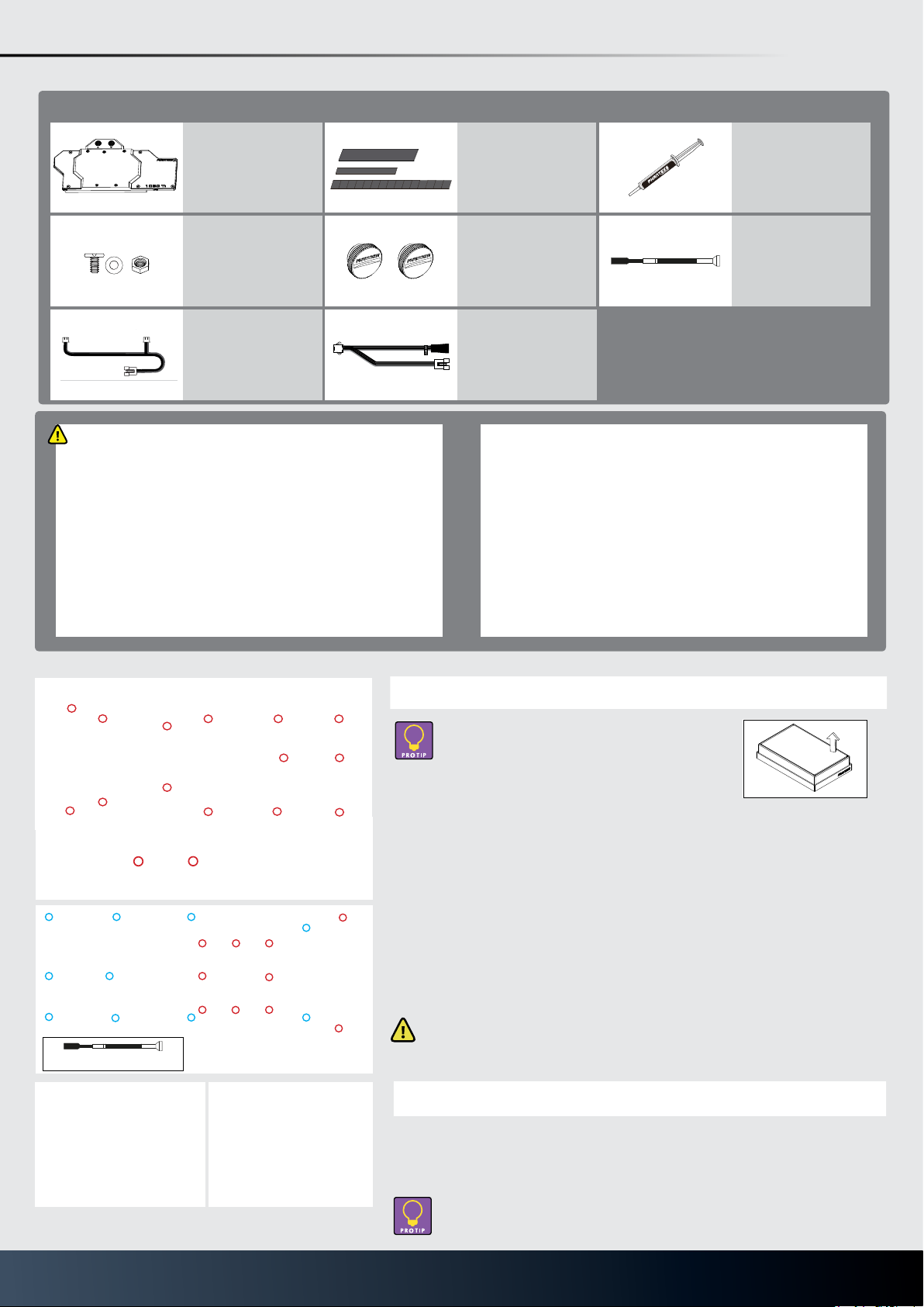
GLACIER G1080 Ti
PH-GB1080Ti_BK01/CR01
PACKAGE CONTENTS
Glacier G1080 Water Block
(Nvidia GTX 1080Ti)
QTY: 1
FOUNDERS EDITION GTX 1080 Ti
Thermal Pads
QTY: 3
Description:
For applying on circuit board on GPU
Thermal Compound (PH-NDC_01)
QTY: 1
M2.5x5, washers
QTY: 10 (Spare 4pcs)
Washers
QTY: 8 (Spare 4pcs)
Hex Nuts
QTY: 4
Phanteks RGB Cable for Phanteks case
(Option a)
QTY: 1
DISCLAIMER - This product is intended for advanced users. Please
consult with a qualied technician for installation, improper installation may result in damage to your equipment. While all eorts
have been made to provide the most comprehensive information
possible, Phanteks assumes no liability expressed or implied for
any damage(s) occurring to your components as a result of using
Phanteks cooling products, either due to mistake or omission on
our part in the below instructions, or due to failure or defect in the
Phanteks cooling products.
INSTALLATION
Phanteks Plugs
QTY: 2
Phanteks RGB Adapter for motherboard
QTY: 1
WARNING - Turn o the power to your system and discharge your
body’s static electric charge by touching a grounded surface – for
example, the metal surface of the power supply or chassis – before
performing any hardware procedure. Phanteks assumes no liability
for any damage, caused directly or indirectly, by improper installation
of any components. If you do not feel comfortable with performing
the installation procedure, consult a qualied computer technician.
*Please do not disassemble the water block. Warranty will be voided.
STEP 1. REMOVING STOCK COOLER
Hex Socket Wrench
QTY: 1
H4 Hex Socket Wrench needed
Take out the top EVA-FOAM from the box to use as a base
for your GPU placement.
Remove all highlighted screws. All heat sink assembly screws should be removed, including
self-adhesive washers on both sides of the PCB (if present).
Make sure to remove the two screws located on the I/O. Keep the screws aside to use in step
5.
Unfasten the screws and use the provided H4 hex socket wrench to remove the hexagonal
spacer-screws (blue). After you remove the housing, do not forget to unplug the fan.
Make sure to keep the hexagonal spacer-screws aside for later use (Step 5).
STEP 2. APPLYING THERMAL COMPOUND
Wipe o the remains of the original thermal compound until components and circuit board are
completely clean (we recommend using a isopropanol cleaning pad). Apply a light coat (see
image) of the PH-NDC-01 thermal paste.
Lightly coat Nvidia GPU Chip with the enclosed thermal paste.
Page 2
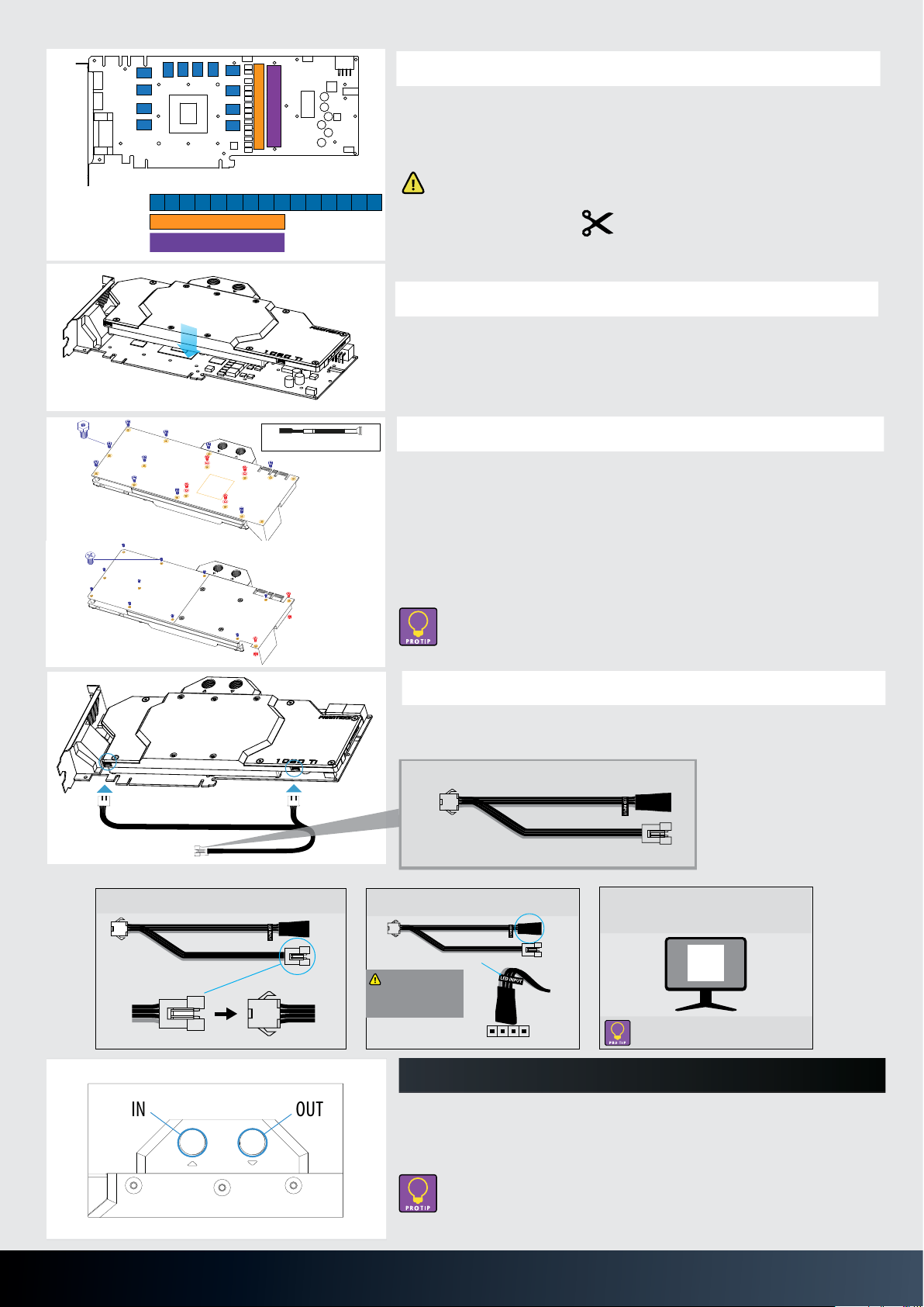
STEP 3. PLACING THERMAL PADS ON PCB
STEP 6. PLACING THE BLOCK ON TO THE GRAPHICS CARD
STEP 7. INSTALLATION OF FITTINGS AND TUBING
Screw in the two G1/4 threaded male ttings, attach the liquid cooling tubes
and
connect the water block(s) into the cooling circuit. Phanteks recommends
Phanteks
ttings with the Phanteks Glacier Series water blocks.
DO NOT FORGET TO PLUG THE REMAINING TWO OPENING.
FOR BEST PERFORMANCE, WE RECOMMEND TO MATCH THE INLET/OUTLET
STEP 5. CONNECTING THE RGB LED (IF CONNECTOR IS PRESENT)
Make sure to connect the RGB LED cable from the waterblock to the GPU PCB
RGB
NOT APPLICABLE FOR MSI ARMOR SERIES
header. (see illustration)
Route the RGB LED cable between the water block and GPU. Carefull y
position the water block onto the graphics card. During this process
please make sure you align mounting holes on the PCB with holes on the
water
block.
DO NOT USE TOO MUCH FORCE BY PRESSING THE BLOCK DOWN TO THE PCB. CHIP DIES
ARE
MAKE SURE TO LAY THE GPU WITH WATER BLOCK FLAT DOWN WITHOUT RESTING ON
THE PCI.
PRONE TO CRACKING.
Use the included 4x M2.5x5 screws and washers (shown in blue) and
11x M2.5x8 screws (shown in red) to tighten the block to the GPU core.
STEP 4. PLACING THERMAL PADS ON PCB
Place thermal pads on the circuit board as shown on the picture below. Refer to
numbering in previous picture when applying thermal pads of di
erent sizes or
thickness. Phanteks made sure to provide customers with more than adequate
quantity of thermal pads to complete this step.
FOR THERMAL PAD 2, ADJUST AND CUT LENGTH ACCORDING
TO GPU VDD VRM CHIPS.
Position 1: 16 x 13 x 1.5mm
Position 2: 20 x 120 x 1.5mm
for memory IC
1 1 1 1 1 1 1 1
2
for Vdd MOSFET
using
OUTIN
CONFIGURATION OF THE WATERBLOCK.
FOR RGB LED CONTROL (SOFTWARE), PLEASE REFER TO THE USER MANUAL OF
YOUR GRAPHIC CARD.
Optional Upgrade
Sync the lighting with a Phanteks case / RGB Motherboard using the Phanteks upgrade kit
(not included).
Once the water block is in place, plug in the remaining RGB LED cable
connector
to the
water block as shown in the illustration.
NOT APPLICABLE FOR MSI ARMOR SERIES
Remove the protective lm and place thermal pads on the PCB as shown on the picture. A
spare thermal pad is included.
for Memory IC
for Vdd VRM
for Vdd MOSFET
hexagonal spacer-screws
1 1 1 1 1 1 1 1
2
3
1 111 111
H4 Hex Socket Wrench needed
Make sure to remove the protective lm on both sides of the thermal pads.
Position 1: 16 x 13 x 0.75mm
Position 2: 10 x 90 x 0.75mm
Position 3: 20 x 90 x 1.25mm
STEP 4. PLACE THE BLOCK ON TO THE GRAPHICS CARD
For thermal pad 2 & thermal pad 3,
adjust and cut length according to
MOSFET chips.
Carefully position the water block onto the graphics card. During the process please make sure
you align the mounting holes on the PCB with the holes on the water block.
STEP 5. INSTALLING THE BACK PLATE
Use the included four (4) M2.5x5 screws and washers(in red) to tighten the block to the
GPU core. *Use the stock hexagonal spacer screws(in blud) from Step 1 that you set aside
and fasten it to the PCB using the provided H4 Hex Socket Wrench.
Once the water block is installed to the PCB, take the back plate and align with the
mounting holes of the hexagonal spacer-screws. Fasten the stock screws that you set aside
in Step 1(in blue) to the hexagonal spacer-screws. Finally, use the two (2) included screws
with the hex nut to complete the installation(in red).
Connect the 2 RGB connectors to the RGB LED strips. With the included RGB motherboard
adapter you can now connect the waterblock directly to your RGB equipped motherboard:
Make sure to lay the GPU with the waterblock at down without resting on the PCI
bracket. Do not use too much force by pressing the block down to the PCB. Chip dies
are prone to cracking.
STEP 6. CONNECTING THE PHANTEKS RGB CABLE
To Phanteks waterblock
To RGB Motherboard
SYNC CASE LIGHTING WITH RGB MOTHERBOARD
1. Connect the RGB LED Adapter to the
case RGB connector.
Case RGB
connector
2. Connect the RGB LED adapter to the
motherboard’s RGB LED header
Make sure the 12V pin
(grey colored cable) is
connected to the 12V
pin on the motherboard
header.
Screw in the two G1/4 threaded male ttings, attach the liquid cooling tubes and connect the
water block(s) into the cooling circuit. Phanteks recommends using Phanteks tting with the
Phanteks Glacier Series water blocks.
Phanteks RGB adapter
12V
MOTHERBOARD
RGB HEADER
12V G R B
Phanteks RGB connector
3. Run the Motherboard RGB LED software
and follow the instructions to set up your
RGB LED lights.
Selected motherboard brands will allow color
callibration of your connected LED strips.
STEP 7. INSTALLALTION OF FITTINGS AND TUBING
- For the best performance, we recommend to match the inlet/outlet conguration
of the water block.
- Do not forget to plug the remaining two openings.
- Always perform a leaktest before starting your computer.
 Loading...