

Page 1

1
Operation
Operation
Operation
Operation Manual
Manual
Manual
Manual
< English
English
English
English version
version
version
version >
Thank
Thank
Thank
Thank you
you
you
you very
very
very
very much
much
much
much for
for
for
for purchasing
purchasing
purchasing
purchasing
LA
LA
LA
LA
series
series
series
series printer
printer
printer
printer
8
8
8
8
th
th
th
th
August,
August,
August,
August, 2011
2011
2011
2011
Version:
Version:
Version:
Version: V2
V2
V2
V2 . 0
0
0
0
� In order to use LA series printer correctly and safely and understand this product’s
capability, please read this manual carefully .
� This manual includes equipment structure, description, technical parameters,
operation manual, safety information, application of software, etc.
� This manual is subjected to change without notice.
� Contents here in contained are believed to be correct, however, please contact us if
you find any mistakes.
Page 2

2
Table of Contents
Chapter 1: Safety Precaution ………………………………………… .. … 3
Chapter 2: Preparation and Procedures for Assembling …………… . … 5
Chapter 3: Machine Structure and Accessories ………………………… 7
Chapter 4: Basic Operation ……………………………………………… .1 0
Chapter 5: Technical Specification …………………………………… .... 11
Chapter 6: Accessory …………………………… . …… ........................ .. 1 2
Page 3

3
1.1
1.1
1.1
1.1
Important
Important
Important
Important Safety
Safety
Safety
Safety Measures
Measures
Measures
Measures
Please read the following instructions before using the printer. Follow cautions and instructions which are labeled
on the printer:
1)
Do NOT block the opening on the top of the printer.
2)
Do NOT insert any object into the printing platform. Prevent spilling liquid onto the printer.
3)
ONLY 220V can be applied.
4)
Connect all the power cord to a single socket extension. Avoid sharing the socket with the devices which will
be on and off frequently.
5)
Avoid using the socket with self-timer control and with the switch on the wall.
6)
Keep your computer away from any device which will release electro-magnetic field, such as wireless phone.
7)
Do NOT use damaged power cord.
8)
If using an extra power cord, keep in mind that the total ampere of this device does not exceed the assigned
ampere of the power. Also, the total ampere of all the device which connect to single socket cannot exceed
the assigned ampere.
9)
Do NOT try to repair the printer.
When
When
When
When encounter
encounter
encounter
encounter the
the
the
the following
following
following
following circumstance,
circumstance,
circumstance,
circumstance, disconnect
disconnect
disconnect
disconnect the
the
the
the power
power
power
power and
and
and
and contact
contact
contact
contact your
your
your
your local
local
local
local distributor
distributor
distributor
distributor for
for
for
for
support:
support:
support:
support:
1)
Power cord or plug is damaged;
2)
Liquid is spilled onto the printer;
3)
The printer fells down or the surface is broken;
4)
Printer does not run normally.
Chapter
Chapter
Chapter
Chapter 1
1
1
1 Safety
Safety
Safety
Safety Precaution
Precaution
Precaution
Precaution
Page 4

4
1.2
1.2
1.2
1.2 Handling
Handling
Handling
Handling Printer
Printer
Printer
Printer Caution
Caution
Caution
Caution
1) Do NOT move the carriage when the power is on.
2) Always use the power switch to turn on or off the printer. Do NOT try to remove the data cable or the power
cord when the machine is on.
3) Make sure the carriage is stabilized in the origin position during transport.
1.3
1.3
1.3
1.3 Handling
Handling
Handling
Handling Ink
Ink
Ink
Ink Tank
Tank
Tank
Tank Caution
Caution
Caution
Caution
1) Please store ink tanks at the place where children cannot reach. Do NOT let children touch the ink tank.
2) If ink is spilled into eyes, immediately wash with water and see your doctor.
3) Do NOT shake the ink tank, this may cause leakage.
4) Please often check the ink content in main ink tank, avoid unnecessary loss due to lack of ink.
5) Please often check the waste ink tank and replace it in time when it becomes full.
1.4
1.4
1.4
1.4 Printer
Printer
Printer
Printer Installation
Installation
Installation
Installation Site
Site
Site
Site
1) Place the printer on a level floor otherwise it will not operate normally.
2) Avoid placing the printer in the area with huge change of temperature and humidity. Do NOT expose the
printer to direct sunlight or heat. Avoid placing the printer in any possible shaking or vibrating area.
3) Leave enough space around the printer to ensure normal ventilation.
4) Place the printer close to the power socket so that power cord can be removed and plugged easily.
Chapter
Chapter
Chapter
Chapter 1
1
1
1 Safety
Safety
Safety
Safety Precaution
Precaution
Precaution
Precaution
Page 5

5
2.1
2.1
2.1
2.1 Environment
Environment
Environment
Environment Requirement
Requirement
Requirement
Requirement
Keep the room temperature between 20 — 30 ℃ , and the humidity between 40 — 60%. Air conditioner and
humidifier may require. Keep a distance from strong radiation field. The floor must be level.
Site
Site
Site
Site Requirement
Requirement
Requirement
Requirement :
2.2
2.2
2.2
2.2 Electrical
Electrical
Electrical
Electrical requirement
requirement
requirement
requirement
The printer only supports AC 220V. A transformer is needed if the area is using AC110V.
The printer must be well grounded (the grounded voltage should be less than 0.3V, and the grounded
resistance should be less than 3Ω).
)
UPS and voltage stabilizer is highly recommended.
Note
Note
Note
Note : 1
1
1
1 .
.
.
. 8
8
8
8 m
m
m
m Heater:
Heater:
Heater:
Heater: 1200W ( 5.5A )、 Printer:
Printer:
Printer:
Printer: 560W ( 2.5A )
2
2
2
2 .
.
.
. 1m
1m
1m
1m Heater:
Heater:
Heater:
Heater: 1350W ( 6A )、 Printer:
Printer:
Printer:
Printer: 560W ( 2.5A )
2
2
2
2 .5
.5
.5
.5 m
m
m
m Heater:
Heater:
Heater:
Heater: 1 7 50W ( 8 A )、 Printer:
Printer:
Printer:
Printer: 560W ( 2.5A )
Note: The total power consumption of the machine cannot be higher than the assigned power on the socket.
Leave at least 900mm of space around the machine.
L: 1 . 8 m - 3080mm
2 . 1 m - 3380mm
2.5m – 3780mm
Chapter
Chapter
Chapter
Chapter 2
2
2
2 Preparation
Preparation
Preparation
Preparation and
and
and
and Procedures
Procedures
Procedures
Procedures for
for
for
for Assembling
Assembling
Assembling
Assembling
900mm
H : 12 6 0mm
W : 99 0mm
900m
Page 6

6
2.3
2.3
2.3
2.3
Procedures
Procedures
Procedures
Procedures of
of
of
of Assembling
Assembling
Assembling
Assembling
1) Move the packing box to the working site and avoid strong shaking.
2) Disassemble the wooden packing box from top to bottom. Check whether the parts are complete or not
according to the packing list.
3) Lift the printer out by a forklift, and move it to the installation site.
4) Check if the printer is level.
5) Get rid of all the parts that stabilize the carriage holder, and install all the spare parts.
6) Move the carriage to the left of printer, then move back to the right manually. During this process, checks if
there are abnormal resistance and carefully inspect the belt & the encoder sensor are situated in proper
position.
7) Ground the printer. The grounded voltage should n o t be more than 0.3V, and the grounded resistance should
be less than 3 Ω .
8) Connect the USB cable between printer and computer. Check if the wires and data cables are plugged in
properly.
9) Install the output and the rip software.
10) Turn on the printer, the carriage will automatically reposition. Keep your hand on the emergency button for
turning off the printer if problem happens suddenly.
11) Send a file to print to test the condition of the printer.
12) Install the printhead, dampers. Connect the damper to the Flush, click the Clean button to choose Depth
clean mode on the software, clean the dampers and the printhead at the same time.
13) Install the ink to the cartridge; fill ink for the first time by using Depth clean.
14) Print nozzle checking and observe the condition of printheads. It is recommended to keep a copy of the test
for reference in the future.
15) Printhead alignment.
16) Start to Print.
Chapter
Chapter
Chapter
Chapter 2
2
2
2 Preparation
Preparation
Preparation
Preparation and
and
and
and Procedures
Procedures
Procedures
Procedures for
for
for
for Assembling
Assembling
Assembling
Assembling
Page 7

7
3.1
3.1
3.1
3.1 Machine
Machine
Machine
Machine Structure
Structure
Structure
Structure
:
(11)
(8)
(7)
(5)
(13)
(14)
(10)
Chapter
Chapter
Chapter
Chapter 3
3
3
3 Machine
Machine
Machine
Machine Structure
Structure
Structure
Structure and
and
and
and Accessories
Accessories
Accessories
Accessories
(
1
)
Left machine box
(
2
)
Cover
(
3
)
Right machine box
(
4
)
Control panel
(
5
)
Cooling fan
(
6
)
Waste tank position
(
7
)
Take-up balancing bar
(
8
)
Take-up tension bar
( 9 ) Rear heater
( 10 ) Middle heater
(
11
) Front heater
( 12 ) Alloy-aluminum Platen
(
13
)
Take-up system
(
14
)
Feeding system
Note: T ake-up system suitable for
2 inch and 3 inch paper core
(9)
(1)
(2)
(6)
(3)
(4)
(15)
(15) Take-up sensor
(12)
Page 8

8
3.2
3.2
3.2
3.2 Name
Name
Name
Name and
and
and
and Function
Function
Function
Function of
of
of
of the
the
the
the Controlling
Controlling
Controlling
Controlling Parts
Parts
Parts
Parts
:
:
:
:
(
Chapter
Chapter
Chapter
Chapter 3
3
3
3 Machine
Machine
Machine
Machine Structure
Structure
Structure
Structure and
and
and
and Accessories
Accessories
Accessories
Accessories
( 1 ) USB data port
( 2 ) Heater safety switch
( 3 ) Printer safety switch
( 4 ) Heater main switch
( 5 ) Printer main switch
( 6 ) Heater power socket
( 7 ) Printer power socket
( 8 ) Vacuum
( 9 ) Take-up auto/manual switch
( 10 ) Direction switch
(
11
) Platform LED
(
12
)
Lamp
(
13
)
Emergency stop
( 3 )
( 7 )
( 12 )
( 4 )
( 5 )
( 1 )
( 2 )
( 6 )
( 11 )
( 10 )
( 8 )
( 9 )
( 13 )
Page 9

9
3.3
3.3
3.3
3.3 Ink
Ink
Ink
Ink Supply
Supply
Supply
Supply System
System
System
System :
Chapter
Chapter
Chapter
Chapter 3
3
3
3 Machine
Machine
Machine
Machine Structure
Structure
Structure
Structure and
and
and
and Accessories
Accessories
Accessories
Accessories
(
1
)
K Cartridge
(
2
)
C Cartridge
(
3
)
M Cartridge
(
4
)
Y Cartridge
(
5
)
Capping system
(
6
)
Waste ink tube
(
7
)
Flash jetting position
(
8
)
Wiper
(
9
)
Capping pad
(10) Ink suction pump
(11) Lamp
( 1 )
( 2 )
( 3 ) ( 4 )
( 5 ) (6) (7) (8) (9) (7) (8) (9) (10) (11)
Dual
Dual
Dual
Dual printhead
printhead
printhead
printhead capping
capping
capping
capping system
system
system
system
Single
Single
Single
Single printhead
printhead
printhead
printhead capping
capping
capping
capping system
system
system
system
Chapter
Chapter
Chapter
Chapter 3
3
3
3 Machine
Machine
Machine
Machine Structure
Structure
Structure
Structure and
and
and
and Accessories
Accessories
Accessories
Accessories
Page 10
10
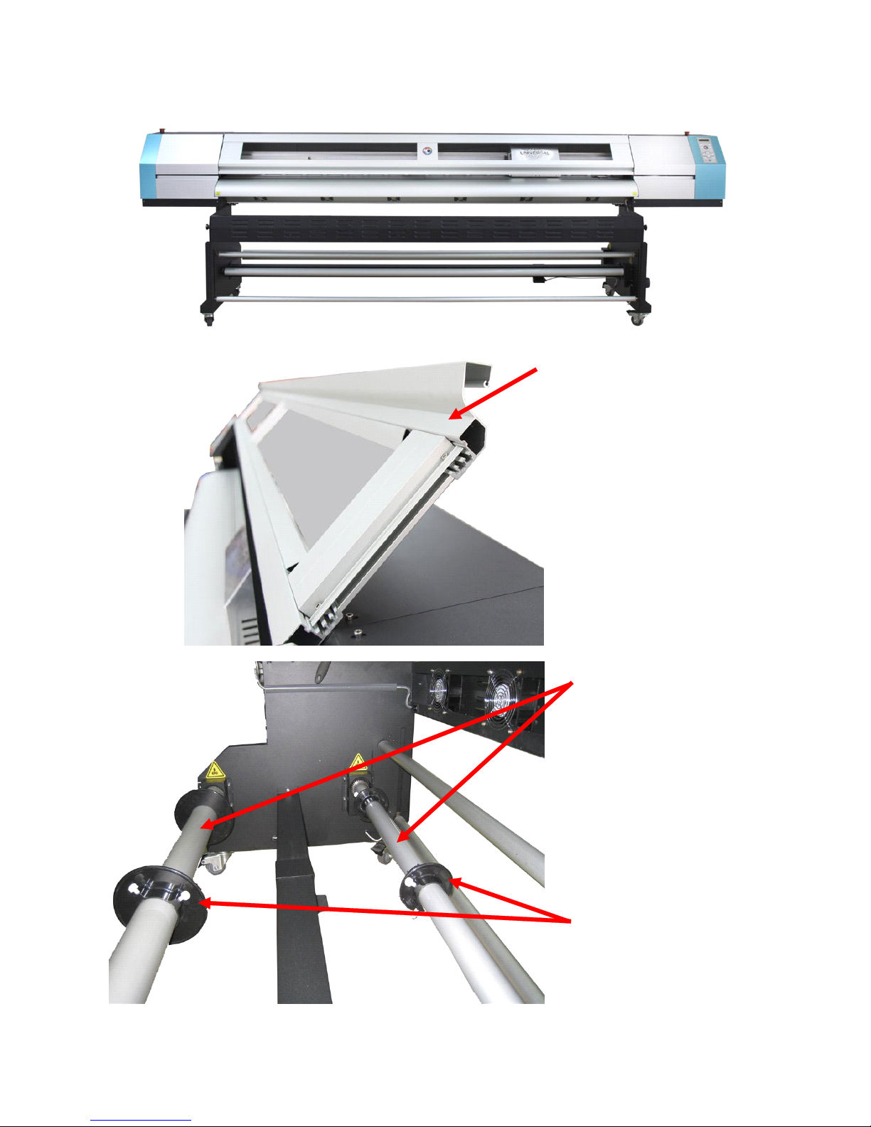
3 . 4 Attachment : (for 2512LA)
(1)Enforced Cover
(2)Single Bar Feeding
and Takeup System
(3) Media Lock
(1)
(2)
(3)
Page 11

11
4.1
4.1
4.1
4.1 Feeding/Take-up
Feeding/Take-up
Feeding/Take-up
Feeding/Take-up system
system
system
system operation
operation
operation
operation
181LA/1812LA, 211LA/2112LA feeding is pulling by pinch rollers directly. Takeup is
controlled by sensor and motor.
2512LA feeding and takeup system is controlled by sensor and motor.
Chapter
Chapter
Chapter
Chapter 4
4
4
4 Basic
Basic
Basic
Basic Operation
Operation
Operation
Operation
O
O
O
O peration:
peration:
peration:
peration:
Direction
switch
Auto/manual
switch
Sto
p
Manual Auto
Stop Clockwise
Anti-
clockwise
Printed side out
Printed side out
Printed side in
Printed side in
Page 12

12
Specification
Specification
Specification
Specification
Model
LA
LA
LA
LA Model
Model
Model
Model
Max. printing width
18 00mm 2100mm 2500mm
Max. media width
1880mm 2180mm 2580mm
Printhead
Epson DX5
Number of printhead 1 / 2 1 / 2 2
Ink
Type
ECO ink / Water based ink / Disperse Dye ink
Color
4 colors (C, M, Y, K)
Volume
1 Liter for each cartridge
Ink supply system
Cartridge
Media
Width
1880mm 2180mm 2580mm
Type Vinyl, Banner, Film, PS Board, KT Board, PVC Foam Board,etc
Feeding System Equipped (Max. weight: 25kg) (Max. weight: 40 kg)
Ph. Cleaning System
Auto cleaning
Heating System Back, middle, front heater, front fan
Clamp Equipped
Data Transfer
USB2.0
Printhead height Adjustable distance from 2mm~10mm
Input Voltage
AC 220V/230V , 50Hz/60Hz
Printer
Dimension/Weight
L30 80 xW9 9 0xH12 60 mm
/2 04 Kg
L33 80 xW9 9 0xH12 60 mm
/2 25 Kg
L3 780 xW9 9 0xH12 60 mm
/ 256 Kg
Package
Dimension/Weight
L3190xW 1100 xH 845 mm
/ 390 Kg
L3490xW 110 0xH 845 mm
/4 13 Kg
L3 79 0xW 110 0xH 845 mm
/4 57 Kg
Chapter
Chapter
Chapter
Chapter 5
5
5
5 Technical
Technical
Technical
Technical Specification
Specification
Specification
Specification
Page 13

13
Code
Code
Code
Code Parts
Parts
Parts
Parts Name
Name
Name
Name Specification
Specification
Specification
Specification Unit
Unit
Unit
Unit 181LA
181LA
181LA
181LA 1812LA
1812LA
1812LA
1812LA 211LA
211LA
211LA
211LA 2112LA
2112LA
2112LA
2112LA 2512LA
2512LA
2512LA
2512LA
Printhead
Printhead
Printhead
Printhead
E411 13 Printhead Cable 1.0*31pin*400cm Piece 4 6 4 6 6
P30164 Damper Epson damper Piece 10 18 10 18 18
Wire
Wire
Wire
Wire
E41020 Power Cable 1.0 Diameter 3M Piece 2 2 2 2 2
E41038 USB 2.0 Cable(Belkin) 1.8m Piece 1 1 1 1 1
Spare
Spare
Spare
Spare
P30170
∮ 6 Tube Connector
Inner Turning Piece 4 4 4 8 8
P30006
∮ 4 Tube Connector ∮ 4 Inner Turning
Piece 4 8 4 8 8
P30007
∮ 4 Tube Connector ∮ 4 Outer Turning
Piece 4 8 4 8 8
P30009 Tube Plug Connector Inner Turning Piece 4 8 4 8 8
P 30003 Tube Plug
Outer Turning ∮ 4
Piece 4 8 4 8 8
P30124 Ink supply tube
∮ 4.2*2.8 ( 500MM)
meter 4 8 4 8 8
P30171 φ 4*2 Soft Tube φ 4*2 meter 4 8 4 8 8
P30188
∮ 2 Y Shape Tube
Connector
White ∮ 2 Outer
Turning
piece 4 8 4 8 8
M20142 Screw 3*10 Piece 4 8 4 8 8
P30040 Plastic Mat Piece 2 2 2 2 2
P30052 Grease Box 1 1 1 1 1
T60063 Sponge Stick Piece 2 2 2 2 2
P30137 Cleaning Bottle 100ML Piece 1 1 1 1
Software
Software
Software
Software
S50026 Printer control software Set 1 1 1 1 1
Other
Other
Other
Other
P30260 Media Fixed Roller
∮ 72 ( ABS Black )
Piece 2
P30056 Media Fixed Roller
∮ 50 ( ABS Black )
Piece 2
~ End
End
End
End ~
Chapter
Chapter
Chapter
Chapter 6
6
6
6 Accessory
Accessory
Accessory
Accessory
 Loading...