

Page 1
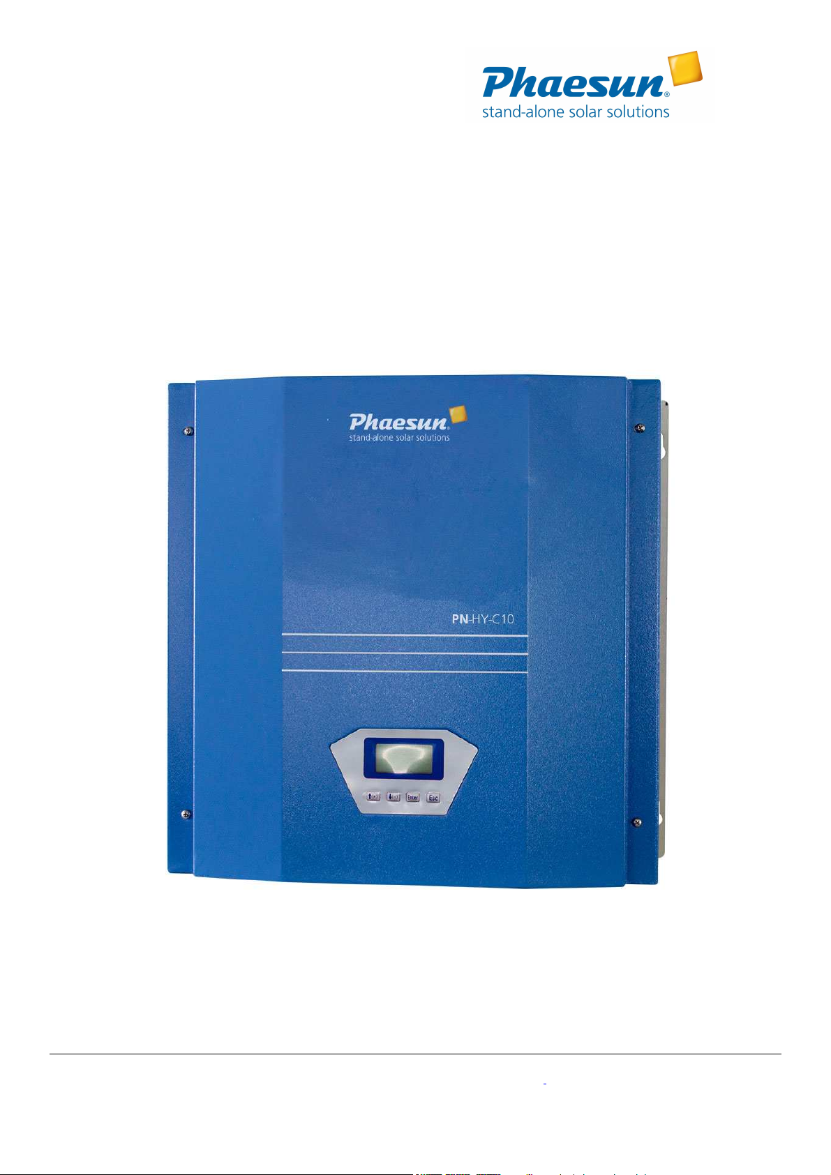
Wind/Solar Hybrid Controller
Wind/Solar Hybrid Controller
Wind/Solar Hybrid ControllerWind/Solar Hybrid Controller
User Manual
User Manual
User ManualUser Manual
Model: HY-C10-24AWM and HY-C10-48AWM
Phaesun GmbH · Brühlweg 9 · 87700 Memmingen · Germany · Telefon +49 (8331) 990 42-12 · i[email protected] · www.phaesun.com
Page 2

1KW Wind/Solar Hybrid Controller User Manual
1KW Wind/Solar Hybrid Controller User Manual
1KW Wind/Solar Hybrid Controller User Manual 1KW Wind/Solar Hybrid Controller User Manual
Notices
Notices
NoticesNotices
1) Battery reverse
Battery reverse----connection is forbidden.
Battery reverseBattery reverse
connection is forbidden.
connection is forbidden.connection is forbidden.
2) Battery virtual connection or damage is one main factor of malfunction. Please check battery voltage and connection
status weekly, clear rust on positive, negative terminal in time; use lead terminal if available.
3) If the malfunction is not easy to eliminate or reason unclear, please write down the phenomenon in detailed record, and
contact manufacturer for help in time.
Installation Environment
Installation Environment
Installation EnvironmentInstallation Environment
1) The equipment should be installed indoor where is well-ventilated.
2) Avoid exposing the apparatus under direct sunshine, exposure, rain, moist, acid mist and dust.
3) Allow at least 20 inches (0.5 m) distance from battery.
4) Ambient Temperature is -20~+55℃; Ambient Humidity is 35~85%RH, no condensing.
5) Do not install the equipment in a compartment with flammable liquids, such as gasoline, or explosive vapors. Be ware
of the flame and the spark.
General Description
The wind/solar hybrid controller is an intelligent control device which can control wind turbine and solar panel at the same
time, specially designed for high-end wind/solar hybrid system and also suitable for wind/solar hybrid power system and
wind/solar hybrid monitoring system. It is used to control the wind generator and solar panel to charge the batteries safely
and efficiently.
With decent appearance, easy operation, visual LCD display and perfect protection functions, the apparatus has high charge
efficiency, low no-load loss.
The wind/solar hybrid controller is the core component of the off-grid power generation system. The performance of the
controller will impact the life and the stability of the whole system, especially the lifespan of battery banks.
1. Performance Description
Performance Description
Performance DescriptionPerformance Description
Reliabili
Reliability
ReliabiliReliabili
ty::::Intelligentzed, modularized design, simple mechanism, powerful functions. With industrial range superior
tyty
components and strict production technology, the controller can be used in relatively bad working environment and has
reliable performance and long life-span.
PWM Stepless Dump load Mode:
PWM Stepless Dump load Mode: dump residual power with division into thousands of stages. It can dump residual power
PWM Stepless Dump load Mode:PWM Stepless Dump load Mode:
while charging battery banks, which is benefit to effectively extend battery longevity.
Voltage Limiting and Current Limiting Ch
Voltage Limiting and Current Limiting Charge Mode:
Voltage Limiting and Current Limiting ChVoltage Limiting and Current Limiting Ch
Phaesun GmbH · Brühlweg 9 · 87700 Memmingen · Germany · Telefon +49 (8331) 990 42-12 · i[email protected] · www.phaesun.com
arge Mode: When battery voltage exceeds the pre-set floating voltage point, the
arge Mode: arge Mode:
Page 3
controller will adopt PWM voltage limiting charge mode. It dumps the excess energy. When wind turbine charging
current exceeds pre-set brake current point, the controller will automatically start brake to protect battery banks.
LCD Display Function:
LCD Display Function: LCD screen can display system status and parameters via visual digital and graphic form. Such as:
LCD Display Function: LCD Display Function:
battery voltage, wind turbine voltage, PV voltage, wind turbine current, PV current, wind turbine power, PV power,
battery power status etc.
Perfect Protection
Perfect Protection Functions
Perfect Protection Perfect Protection
Functions:::: Battery over charge protection, Battery over discharge protection, Battery anti-reserve
FunctionsFunctions
connection protection, wind turbine current-limiting charge, automatic brake, manual brake; solar anti-reverse charge
protection, solar anti-reverse connection protection, lightning protection, etc.
2. Installation Instruction
Installation Instruction
Installation InstructionInstallation Instruction
Step 1.
Step 1. Check the package and then check the controller for damage after unpacking. Damaged controller cannot be
Step 1.Step 1.
installed in the system.
Step 2.
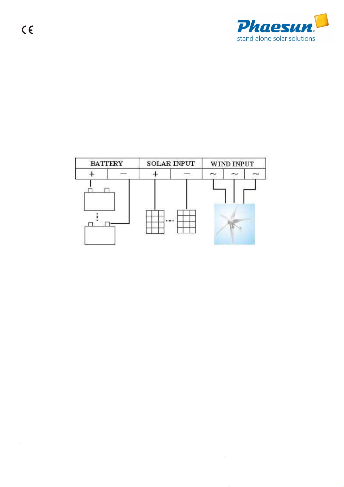
Step 2. For controller whose dump load box is separated, please connect dump load box to the “DUMP LOAD” terminals of
Step 2.Step 2.
the controller.
Step 3.
Step 3. Connect battery positive pole to the positive (+) “BATTERY” terminal, Connect battery negative pole to the negative
Step 3.Step 3.
(-) “BATTERY” terminal with copper core cable.
(Note: Although the controller has anti
Note: Although the controller has anti----reverse connection protection function, wrong polarity of battery shall be forbidden!
Note: Although the controller has antiNote: Although the controller has anti
Please refer to Appendix I for copper wire over current capability
Please refer to Appendix I for copper wire over current capability.)
Please refer to Appendix I for copper wire over current capabilityPlease refer to Appendix I for copper wire over current capability
Step 4.
Step 4. Connect the wind turbine output lines to the “WIND INPUT” terminals in condition of wind turbine in action-less or
Step 4.Step 4.
reverse connection protection function, wrong polarity of battery shall be forbidden!
reverse connection protection function, wrong polarity of battery shall be forbidden!reverse connection protection function, wrong polarity of battery shall be forbidden!
low speed.
Step 5.
Step 5. Connect solar panels to the “SOLAR INPUT” terminals.
Step 5.Step 5.
Step 6.
Step 6. Check all connection is proper and firm or not.
Step 6.Step 6.
Step 7.
Step 7. If the controller has communication function, user can read and set relevant parameters via software.
Step 7.Step 7.
Step 8.
Step 8. User can set relevant parameters through LCD buttons.
Step 8.Step 8.
Phaesun GmbH · Brühlweg 9 · 87700 Memmingen · Germany · Telefon +49 (8331) 990 42-12 · i[email protected] · www.phaesun.com
Page 4
3. LCD Display Instruction and Key Specification
LCD Display Instruction and Key Specification
LCD Display Instruction and Key SpecificationLCD Display Instruction and Key Specification
4.1 LCD Display Instruction
4.1 LCD Display Instruction
4.1 LCD Display Instruction4.1 LCD Display Instruction
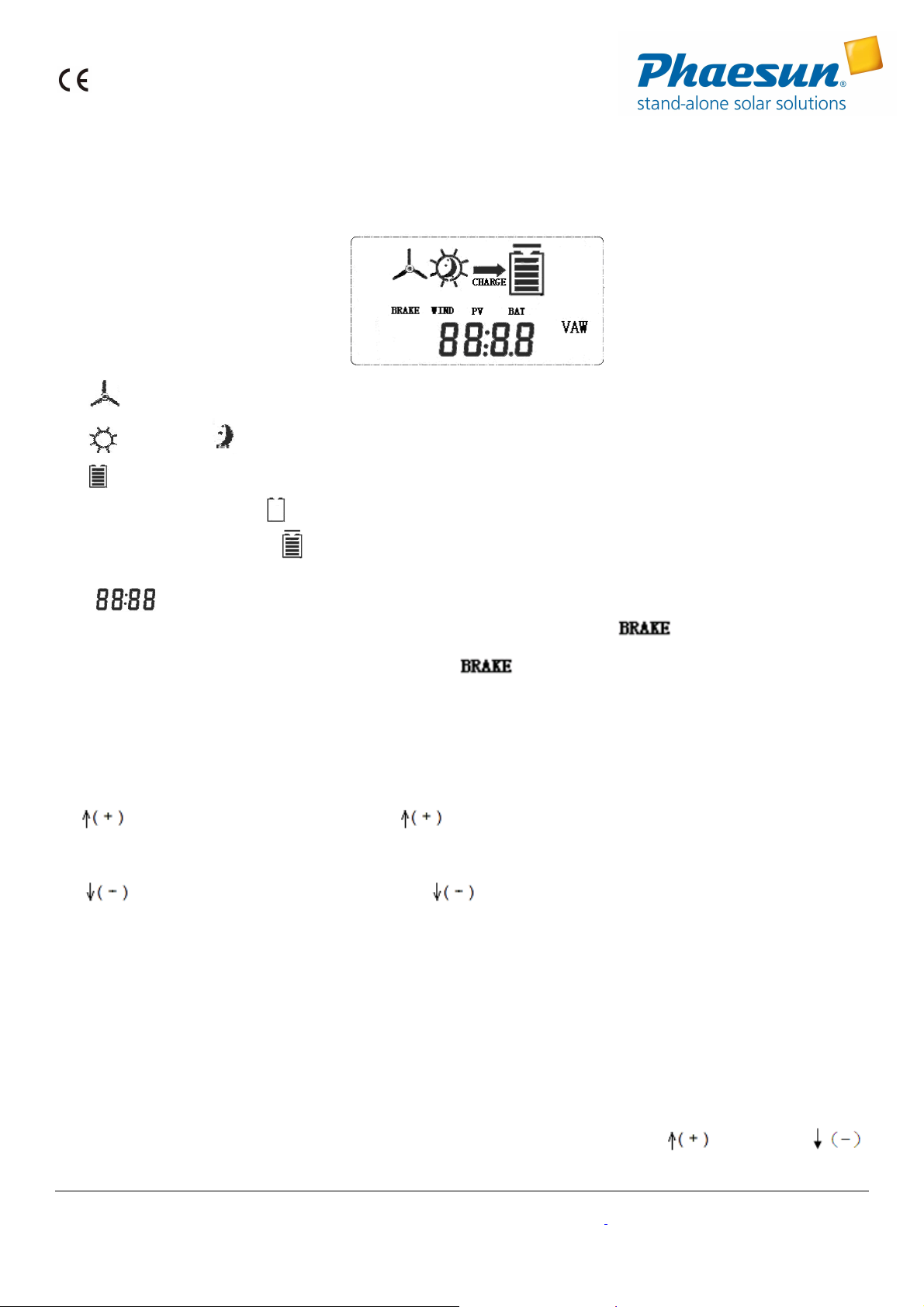
1) Wind turbine symbol.
2) Day symbol. Night symbol.
3) Battery symbol,inner strip graph indicates the battery power status. Five inner horizontal strips display indicates the
battery is full. The symbol shall be flashing when the battery is over-discharge, flashing will not stop until battery
voltage recover. The symbol shall be flashing when the battery is over charge, flashing will not stop until battery
voltage recover.
4) Parameters display symbol. Each system parameters are displayed via visual digit and graph.
5) Press the "Enter" key and "Esc" button at the same time, LCD displays the symbol which indicates wind turbine
in brake status. Wind turbine will stop rotating or running in low speed under brake status. Press the "Enter" key and "Esc"
button at the same time under brake status, the symbol will disappear and brake status is released. In normal
situation, the wind turbine shall be in running status rather than brake status.
4.2 Button Specification
4.2 Button Specification
4.2 Button Specification4.2 Button Specification
LCD backlight will be on after pressing any button. The backlight will go out to save power if there is no button operation for
10 seconds.
" ": Up/ Increase. In browsing status, press to check the previous parameter. In setting window, press this
button to check the next adjustable parameter or increase the value of current parameter.
" ": Down/Decrease. In browsing window, press to check the next parameter. In setting window, press this
button to check the previous adjustable parameter or decrease the value of current parameter.
"Enter": Set/Confirm. In browsing window, press "Enter" to access setting window. In setting window, press this button to
save parameters and return back to browsing window.
"Esc": Cancel/Manual reset. In setting window, press "Esc" to return to browsing window without saving the modified
parameters.
4.3 Parameters Browsing
4.3 Parameters Browsing
4.3 Parameters Browsing4.3 Parameters Browsing
1) When power is on, the LCD is under browsing window and displays battery voltage: XX.X V;
2) In browsing window, LCD will circularly display the following parameters by pressing "
Phaesun GmbH · Brühlweg 9 · 87700 Memmingen · Germany · Telefon +49 (8331) 990 42-12 · i[email protected] · www.phaesun.com
" button and " "
Page 5
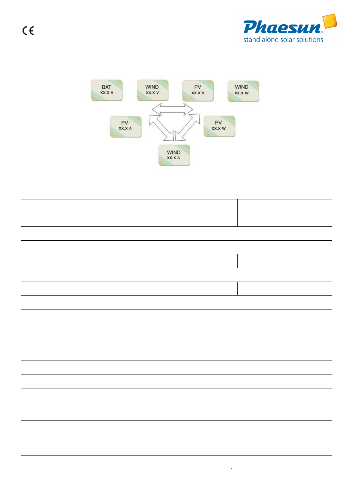
button.
4. Technical Data
Technical Data
Technical DataTechnical Data
Product Model
Product Model HY
Product ModelProduct Model
HY----C10
C10----24AWM
HYHY
C10C10
24AWM HY
24AWM24AWM
HY----C10
HYHY
Rated Battery Voltage 24V 48V
Rated Wind Turbine Input Power 1000W
Maximum Wind Turbine Input Power 1500W
Wind Turbine Brake Current 42A 21A
Rated Solar Input Power 300W
Floating Charging Voltage 29V 58V
Display Mode LCD
Quiescent Current ≤20mA
Ambient Temperature & Humidity
-20~+55℃/35~85%RH(Without Condensation)
Temperature Compensation Function
(Optional)
-4mV/℃/2V ,–35℃--+80℃ ,Precision:±1℃
Package size (L×W×H) 51×50×25cm
C10----48AWM
48AWM
C10C10
48AWM48AWM
Net Weight 10kg
Gross Weight 11kg
In order to serve our c
In order to serve our customers better. Our company can adjust parameters configuration according to customer’s
In order to serve our cIn order to serve our c
requirement.
requirement.
requirement.requirement.
5.
Troubleshooting
Troubleshooting
TroubleshootingTroubleshooting
ustomers better. Our company can adjust parameters configuration according to customer’s
ustomers better. Our company can adjust parameters configuration according to customer’s ustomers better. Our company can adjust parameters configuration according to customer’s
If your phenomenon is out of following descriptions or should you have any problems about these products, please contact
Phaesun GmbH · Brühlweg 9 · 87700 Memmingen · Germany · Telefon +49 (8331) 990 42-12 · i[email protected] · www.phaesun.com
Page 6
manufacturer in time.
Phenomenon
Phenomenon Troubleshooting
PhenomenonPhenomenon
Troubleshooting
TroubleshootingTroubleshooting
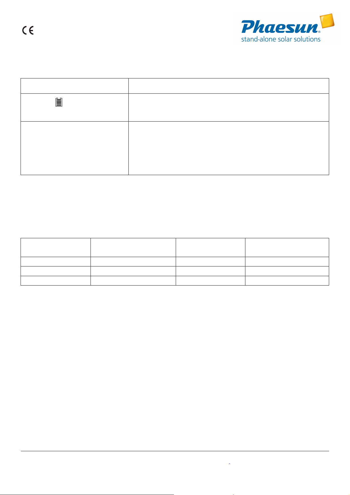
Battery is over-voltage, check battery voltage, and whether the cables are
The symbol flashing, without charge
well-connected or not, re-connect all components.
or discharge
a) Firstly, open the software “parameter”-“control”, please check if the setting is
“BRAKE”. If yes, please cancel it.
LCD display “BRAKE” all the time
b) Secondly, Disconnect wind turbine, battery with controller successively.
Reconnect them a few minutes later, then check if it comes back to normal.
6. Guarantee and Liability
Guarantee and Liability
Guarantee and LiabilityGuarantee and Liability
One year warranty is available for our product from the date of delivery. If the product is out of warranty or damaged by
transportation, inappropriate operation, human factors, force majeure, no guarantee is made.
Appendix
Appendix
AppendixAppendix
Appen
Appendix I:
dix I: Copper Wire Over
AppenAppen
Copper Wire Over----current Capacity
dix I:dix I:
Copper Wire OverCopper Wire Over
current Capacity
current Capacitycurrent Capacity
Wire Diameter(mm²) Over current capability(A) Wire Diameter(mm²) Over current capability(A)
4 ≤20 16 ≤90
6 ≤30 25 ≤125
10 ≤50
Phaesun GmbH · Brühlweg 9 · 87700 Memmingen · Germany · Telefon +49 (8331) 990 42-12 · i[email protected] · www.phaesun.com
 Loading...