

Page 1
PHAESUN GmbH
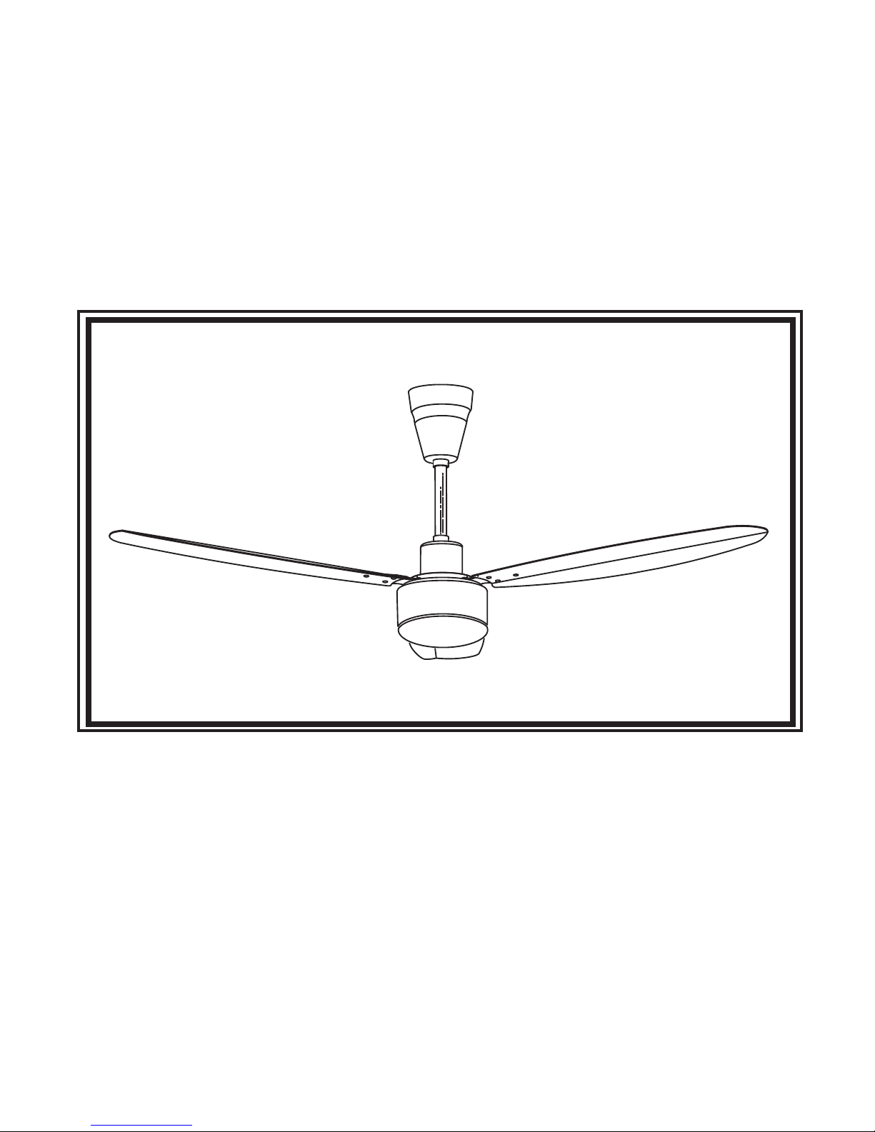
INSTRUCTION MANUAL
READ AND SAVE THESE INSTRUCTIONS
Page 2
WARNING: To avoid fire shock and serious personal injury, follow these instructions.
Important Safety Instructions
Table of Contents
WARNING
!
1. Read all instructions and safety information before installing your new fan.
Review the accompanying assembly diagrams.
2. Before installing the fan, disconnect the power by removing fuses or turning off circuit
breakers.
3. Make sure that all electrical connections comply with local codes, ordinances, or
National Electrical Codes. Hire a qualified electrician or consult a do-it -yourself
wiring handbook if you are unfamiliar with installing electrical wiring.
4. Make sure the installation site you choose allows the fan blades to rotate without any
obstructions. Allow a minimum clearance of 7 feet from the floor to the trailing edge of
the blades.
5. If you are mounting the fan on a ceiling outlet box, use a metal outlet box. Secure the
box directly to the building structure. The outlet box and its support must be able to
support the moving weight of the fan ( at least 50 lbs.). Do not use plastic outlet box.
Attach the mounting bracket using the hardware supplied with the ceiling outlet box.
6. If you are mounting the fan to a joist, make sure it is strong enough to support the
moving weight of the fan (at least 50 lbs.)
7. After you install the fan, make sure that all connections are secure, this will prevent
the fan from falling.
8. Do not insert anything into the fan blades while the fan is operating.
9. Turn the fan off and wait for it to stop before reversing fan direction.
10. To reduce risk of electrical shock and personal injury, do not install fan on sloped
ceiling.
11. o reduce risk of electrical shock and personal injury, do not use this fan with any
solid-state.
12. To reduce risk of personal injury, use only the two steel screws, and lock washers,
provided with the fan for mounting to the outlet box.
Tools Needed for Assembly ............................................... 1
Assembly Drawing ............................................................ 1
Parts List ......................................................................... 1
How to Assemble Your Ceiling Fan .................................. 1,2
How to Mount Your Fan Blades .......................................... 2
How to Hang Your Ceiling Fan ....................................... 2,3
How to Wire Your Ceiling Fan ............................................ 3
How to Operate Your Ceiling Fan ...................................... 4
Maintenance ................................................................... 5
Page 3
1
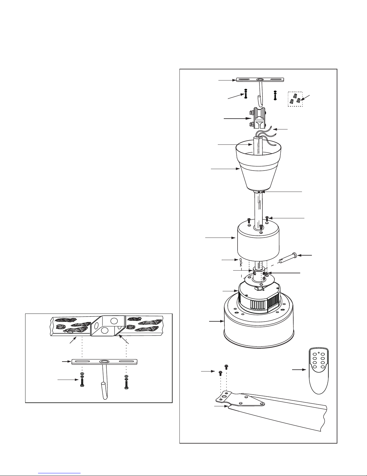
Parts List
CAUTION: To avoid possible electrical shock,
be sure electricity is tu rne d off at the main fuse
box before assembl ing .
1. Securely attach the J- Hoo k to the ceiling joist
using the screws/wash ers /spring washers
supplied with the ceili ng joist (Figure 2).
1. J - Hook (1)
2. Screw (2)/Washer (2)/Spring Washer (2)
3. Wire Connectors (3)
4. Rubber grommet (1)
5. Downrod (1)
6. Canopy (1)
7. Yoke Cover (1)
8. Canopy Setscrew (2)
9.Yoke Cover S ets cre w (3)
10 Downrod Support
11. Downrod Support Setscrew (2)
12. Clevis Pin (1)
. Hairpin Clip (1)
14. Fan Motor Assembly (1)
15. Receiver Assembly (1)
16. Hand-Held Remote Transmitter (1)
17. Fan Blade Set (3)
18. Blade Setscrew (6)
19. Fan Wires
.
13
Assembly Drawing
Tools Needed for Assembly
-
- Adjustable wrenc h - Wire Cutters
- Stepladder
Philips Screwdri ver - Slotted Screwdriver
This Manual Is Designed to Make it as Easy as Possible for You to
Assemble, Install, Operate and Maintain Your Ceiling Fan
How to Assemble Your Ceiling Fan
2.Remove the clevi s pin a nd hairpin clip from the
downrod and retain t hem f or reinstallation in
step 4.
Figure 2
Ceiling Joist
Screw ( 2)
Washer (2)
Spring Wash er (2)
J - Hoo k
Outlet Box
6
18
17
16
Figure 1
3
4
19
1 2
3 4
5 6
F/R OFF
5
2
1
12
13
7
14
15
11
10
9
8
Page 4
How to Assemble Your Ceiling Fan (Cont’d)
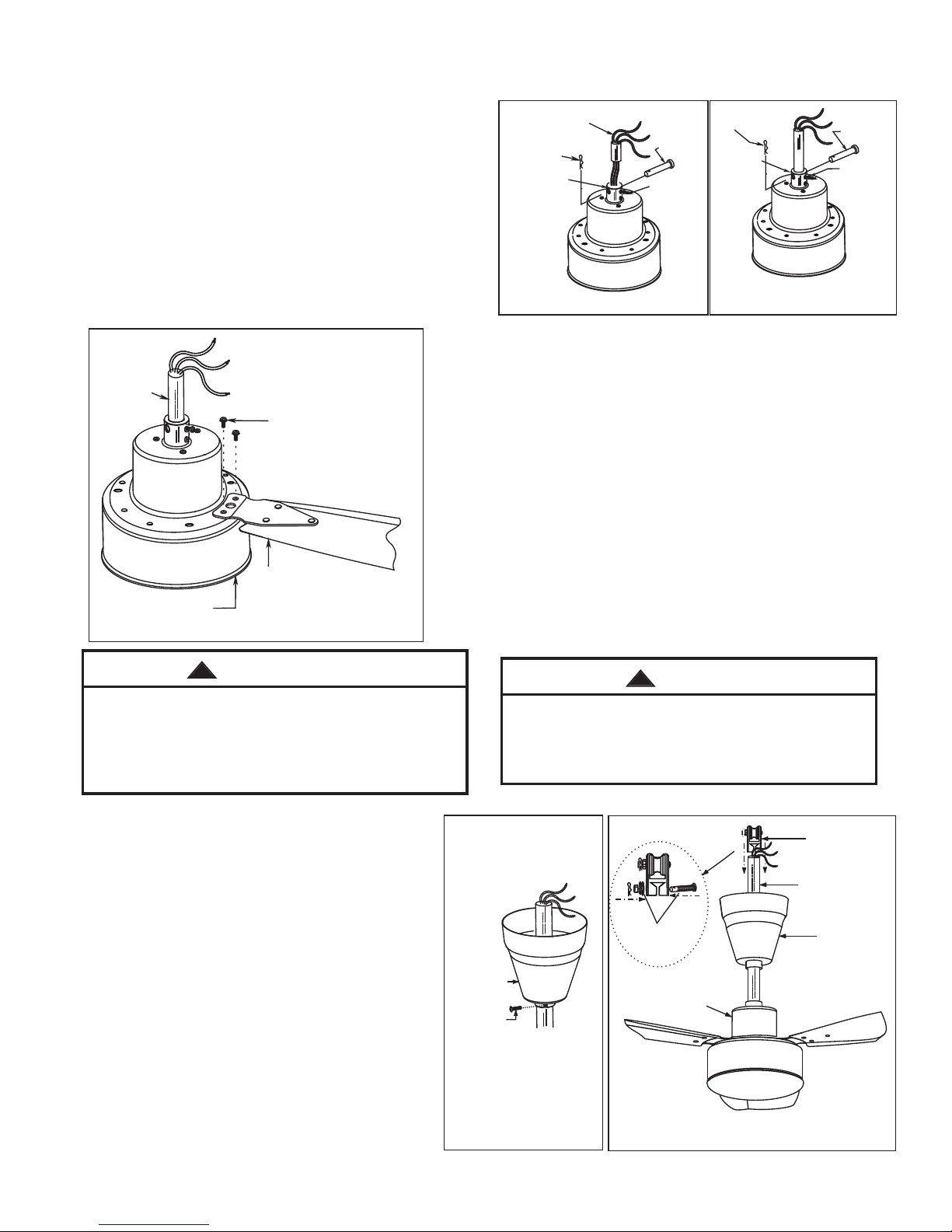
3. First, loosen the two se tsc rews in the downrod
support, carefully th rea d for electrical wires through
downrod (Figure 3).
4. Put the downrod into the d ownrod support and align
the clevis pin holes in the d ownrod with the holes in
the downrod suppor t. In sta ll the clevis pin and secure
with the hairpin clip, th en re -tighten the two setscrews
(Figure 4) securely whi le pulling up on the downrod.
The hairpin clip must be properly installed to prevent
the clevis pin from getti ng lo ose. Pull on the downrod
to make sure the clevis pin i s pro perly installed.
How to Mount Your Fan Blades
1. Mount the fan blade to the f an mo tor assembly
using two blade setscre ws (F igure 5). Repeat
for the remaining two bla des .
2. Make sure the setscrew s sec uring the fan motor
assembly are tight and th at th e blades are properly
seated.
NOTE: Periodically check b lad e har dware and
resecure if necessary.
How to Hang Your Ceiling Fan
1. Place the canopy into th e dow nrod as shown
in figure 6.
2. Remove the setscrew/ was her/spring washer
from the rubber grommet (Fig ure 7 a) and
retain them for reinstalla tion in step 3.
3. Put the rubber grommet i n the d ownrod and
securely install it by us ing s etscrew/washer/
spring washer supplie r wit h the downrod
(Figure 7).
2
WARNING
!
To reduce the risk of personal injury, do not
bend the blades when installing , bal anc ing
the blades or cleaning the fan. Do no t ins ert
for reign objects in the between th e rot ating
fan blades.
WARNING
!
Do not connect fan blades until the f an
is completely installed. I nst all ing the fan
with blades assembled may re sul t in
damage to the fan blades.
Figure 3
Figure 4
Electrical
Wires
Hairpin Clip
Clevis Pin
Setscrew
Downrod
Support
Hairpin Clip
Clevis Pin
Setscrew
Downrod
Support
Figure 5
Fan Bl ad e Set (3)
Fan Mo to r
Asse mb ly
Downrod
Blad e Se tscrew (6)
Rubb er
Grom me t
Cano py
Figure 6
Downrod
Sets cr ew
Figure 7
Yoke Cove r
Cano py
Down ro d
Fig. 7a
Remo ve d
+
Page 5
Figu re 8 a
Figu re 8 b
Rubbe r
Gromm et
J-Hoo k
4
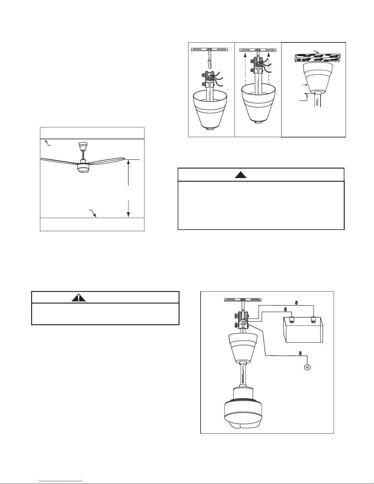
rubber grommet rests pr ope rly on the J-hook.
As shown in figure 8a and 8 b.
5. Securely attach the ca nop y/yoke cover to the
downrod/rubber g rom met assembly by using
two canopy/yoke cover s ets crews supplied
with your ceiling fan (Fi gur e 9).
NOTE: This step is applicable after
necessary wiring is completed.(See page 3)
. Hang the fan up into the J-ho ok, be sure the
How to Hang Your Ceiling Fan (Cont’d)
WARNING
!
It is critical that the clevis pin in the downrod support
be properly installed and the setscrew securely tightened. Failure to verify that the pin and setscrew are
properly installed (as shown in Figure 4) could result
in the fan falling.
How to Wire Your Ceiling Fan
If you feel that you do not have enough electrical wiring knowledge or experience,
have your fan installed by a licensed electrician.
WARNING
To avoid possible elec tri cal shock, be sure
electricity is turned o ff before wiring.
1. Securely connect the r ed wi re (DC +) from fan
to the power supply wire ( + ) us ing w ire connector
supplied.
2. Securely connect the b lac k wire (DC -) from fan to
the power supply wire ( - ) usi ng wi re connector
supplied.
3. Connect the green/ye llo w grounding lead from the
fan to the supply groundi ng co nductor using
wire connector.
As shown in figure 11.
Caution: The Power Supply must be D C12 V (or DC24V) and the wire connection must be + to +
and - to -. These fans are reverse p ola rity protected, fan will not work if wired incorrectly, please
ensure pos and neg wiring is connec ted c orrectly.
3
6. The fan must be hung with at least 7 feet of
clearance from floor to b lad es (Figure 10)
Figure 10
Floor
less than
7 feet
No
Ceili ng J oist
Figu re 9
Canop y
+
Canop y
setsc re w
Ceiling
Figure 11
+
-
Power Supply :
DC1 2V or DC2 4V
(Ba ttery )
Red (DC + )
Black ( DC - )
Green/yellow(Ground)
Page 6
How to Operate your Ceiling Fan
4
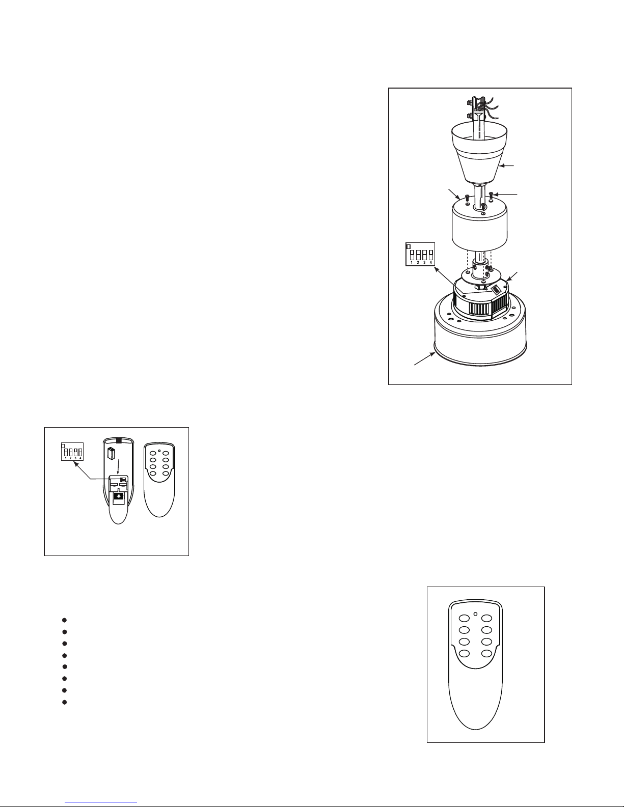
1. Setting the Code: The remote unit has 16 different code
combination. It may be ne ces sary to test a couple frequency
code settings to improv e sig nal reception and/or eliminate
interference from oth er re mote control household items.
Multiple fans should ha ve di fferent code settings to allow
independent fan contr ol. To set the code, perform these steps.
2. Transmitter: Remove b att ery cover. Press firmly below arrow
and slide battery cover o ff. Slide code switches to your choice
of up or down position. Fac tor y set ting is all down. Do not use
this position. With a small sc rew driver or ball point pen slide
firmly up or down (Figure 1 2). R eplace battery cover on the
transmitter.
3. Receiver: Slide code s witches to the same positions as set
on your transmitter (Figur e 13) .
Note1: When you set the cod es, p lease remove the yoke cover
setscrews (3) from the yo ke co ver first and then replace the
screws after the codes se tti ng completed.
Note2: Receiver in cont rol lers system features an automatic
learning functio n. Th ere a re no frequency switches on the
receiver unit. The rece ive r will automatically scan the frequency
from the hand-held cont rol i f an changes are made. The frequency
settings should be chan ged only in the case of interference or
if multiple ceilin g fan s with the same type of control system are
installed in the sam e str uct ure.
Hand-H el d Remote Tra ns mi tt er
Figure 1 2
Code Sw it ch es
ON
1 2
3 4
5 6
F/R OFF
Batt ery
9V x 1
5. The remote buttons instruct as below (as shown in figure 14):
OFF Button - fan off
1st Button - high speed
2nd Button - medium high speed
3rd Button - medium speed
4th Button - medium low speed
5th Button - low speed
6th Button - minimum speed
F/R Button - toggles between a ir up flow and air downflow
Figure 14
1 2
3 4
5 6
F/R OFF
4. Operating & Using Remo te Tra nsmitter:
Install one 9 volt battery (in clu ded) into the hand-held remote
transmitter. Press any fan sp eed b utton and allow the receiver to
scan (normally within 3 -5 se conds) the fan is now programmed and
ready for normal operat ion .
Note: If not using for long p eri od of time, remove battery to
prevent damage to trans mit ter. Store the transmitter a way f rom
excessive heat or humid ity.
Rece iv er
Un it
Figure 13
ON
ON
2
3
4
1
Moto r Bo ttom
Cove r
Code Switches
Yoke Cove r
Yoke Cove r
Sets cr ew
Cano py
Page 7
Maintenance
1. Periodic cleani ng of y our new ceiling fan is
the only maintenance th at is n eeded.
2. When cleaning, use onl y a soft brush or lint
free cloth to avoid scratchi ng th e finish.
3. Abrasive cleanin g age nts are not required
and should be avoided to pr eve nt damage
to finish.
RECOMMENDED: Period ically check that the blade sets to the fan motor setscrew are secure and
tight.
!
Do not use solvents when cleaning your
ceiling fan. It could damage the motor
and create the possibility of electrical
shock.
WARNING
5
Page 8

 Loading...