

PGS PG-40400S0L User Manual
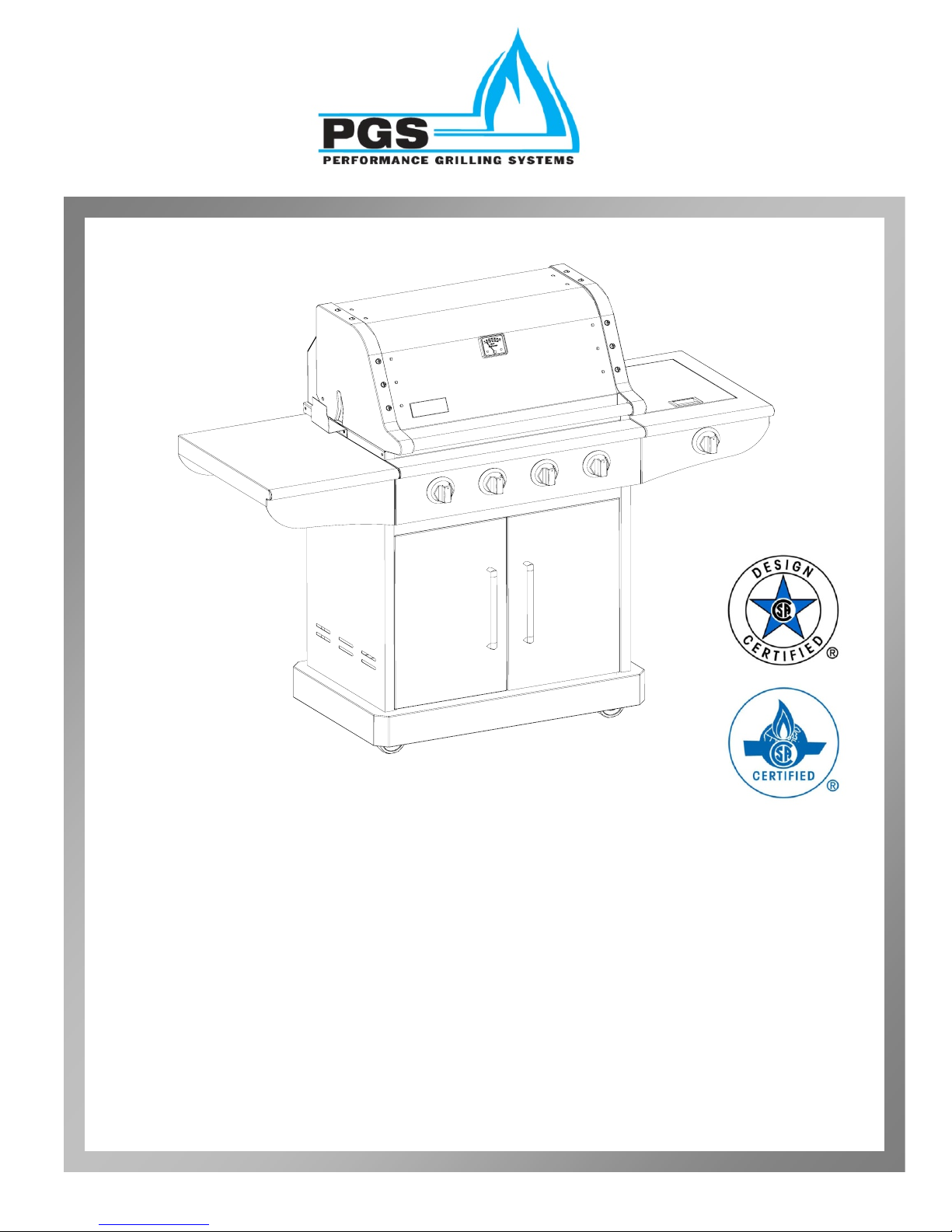
H40 SERIES GAS BBQ GRILL
MODEL NUMBER: PG-40400S0L
ITEM NUMBER: PGS H40PSB
FOR OUTDOOR USE ONLY
USER’S MANUAL
TM
Copyright October 2010-AEI Corporation
SAFETY SYMBOLS
The symbols listed below are being used throughout this User’s Manual. Please pay special
attention to them. The meaning of each of the symbols are listed here:
DANGER– this symbol indicates an imminently hazardous situation which
will result in death or serious bodily injury if not properly followed.
WARNING– this symbol indicates a warning of potential serious bodily injury if
the instructions are not strictly followed. Please be sure to read and follow all
these messages carefully.
CAUTION– this symbol indicates a potentially hazardous situation which
may result in minor or moderate bodily injury if the instructions are not properly
followed.
IMPORTANT WARNINGS
YOU MUST READ THIS OWNER’S GUIDE BEFORE OPERATING
YOUR GAS GRILL
DANGER
If you smell gas:
1. Shut off gas to the appliance.
2. Extinguish any open flames.
3. Open lid.
4. If the odor continues, keep away from the appliance and immediately call your
gas supplier or fire department.
Leaking gas may cause a fire or explosion which can cause serious bodily injury or
death, or damage to property.
WARNING
1. Do not store or use gasoline or other flammable liquids or vapors in the
vicinity of this or any other appliance.
2. An LP cylinder not connected for use shall not be stored in the v icinity of
this or any other appliance.
Follow all leak-check procedures carefully in this manual prior to barbeque
operation. Do this even if the barbeque was dealer assembled and/or installed.
WARNING
IMPORTANT WARNINGS (continued)
NOTE TO INSTALLER:
The instructions must be left with the owner and the owner of the grill should keep
them for future use
THIS GAS APPLIANCE IS DESIGNED FOR OUTDOOR USE
ONLY.
WARNING
Do not try to light this appliance without reading “Lighting Instructions” section in
this manual found on pages 11 and 12.
CALIFORNIA PROPOSITION 65
1. Combustion by products produced when using this product contain chemicals
known to the State of California to cause cancer, birth defects, and other
reproductive harm.
2. This product contains chemicals including lead and lead compounds, known to
the State of California to cause cancer, birth defects, or other reproductive harm.
Wash your hands after handling this product.
This product is for residential use only. Do not use for
commercial cooking.

TABLE OF CONTENTS
BEFORE YOU BEGIN
MESSAGE TO OUR USERS PAGE 1
PROPANE & GAS WARNINGS PAGE 1
ASSEMBLY
PARTS LISTING PAGE 2
DETAILED DRAWING OF GRILL PAGE 3
ASSEMBLY INSTRUCTIONS STEP I PAGE 4
ASSEMBLY OF SIDE BURNER KIT PAGE 5
ASSEMBLY INSTRUCTIONS STEP II PAGE 7
GAS CONNECTION AND
PROPANE HOSE SAFETY NOTICE PAGE 8
GAS CONNECTION PAGE 8
LEAK TESTING PAGE 11
SAFETY TIPS PAGE 12
FINAL INSTALLATION CHECK LIST PAGE 12
GRILL LIGHTING INSTRUCTION PAGE 13
OPERATING INSTRUCTION PAGE 14
GRILLING BASICS, COOKING CHART PAGE 17
SIDE BURNER OPERATING INSTRUCTION PAGE 18
CARE & MAINTENANCE PAGE 19
TROUBLE SHOOTING PAGE 20
FOOD SAFETY PAGE 21
GRILL STORAGE PAGE 21
WIND EFFECT ON GRILL PAGE 21
WARRANTY INFORMATION PAGE 22
PRODUCT REGISTRATTION PAGE 23
TM
MESSAGE TO OUR USERS
CONGRATULATIONS! You have purchased a truly exceptional outdoor cooking appliance.
Your PGS grill has been designed to give you many years of outdoor cooking enjoyment. Our
grills have been designed with quality, dependability, performance, and safety features.
Please contact our customer service at (949) 474-3070 if you have any questions.
Please read this User’s Manual carefully. Failure to follow the provided instructions
can result in seriousl bodily injury and/or property damage.
Some parts of this grill may have sharp edges. Please wear suitable protective gloves when
assembling product.
IMPORTANT: This grill is intended for outdoor use only and is not intended to be installed in or
on recreational vehicles or boats or used in a combustible BBQ Island or in a commercial
application.
NOTE TO CONSUMER: Leave this User’s Manual in a convenient place for future reference.
WARNING
READ THIS SECTION FIRST BEFORE INSTALLING THE GRILL
This grill is designed to use LP gas only. Please use the grill with the regulator supplied by
with the grill.
A natural gas conversion kit is available, please see your dealer or contact AEI Corporation
at (949) 474-3070. Do not attempt to convert this grill unless you have a factory designed
conversion kit.
The installation of this appliance must conform with local codes or, in the absence of local
codes, with either the National Fuel Gas Code, ANSI Z223. 1, or CAN/CGA B149.1,
Natural Gas Installation Code or CAN/CGA-B149.2, Propane Installation Code.
The LP-gas supply cylinder is to be constructed and marked in accordance with the
specifications for LP-gas cylinders of the U.S. Department of Transportation (DOT) or
the National Standard of Canada, CAN/CSA-B339, Cylinders, Spheres and Tubes for
the Transportation of Dangerous Goods.
If an external electrical source is utilized, the outdoor cooking gas appliance, when
installed, must be electrically grounded in accordance with local codes or, in the absence of
local codes, with the National Electrical Code, ANSI/NFPA 70-1990, or the Canadian
Electrical Code, CSA C22.1. Keep the power cord of the motor away from the hot
surfaces of the grill while in use. Remove and store the motor in a dry place when not in
use.
This grill is safety certified for use in the United States and Canada only. Never modify to
use in other countries. Modification may cause serious bodily injury or property damage.
AEI is not responsible for any modifications, and all warranties will be void.
1

GRILL PARTS LISTING
PARTS LISTING FOR H30 and H40. Please note, H40 includes a side burner kit (not available on H30). Additionally, H40
KEY # DESCRIPTION H3B QTY H4B QTY NOTES
01 LID HANDLE TUBE GRILL 73901 1 74901 1
01D CART DOOR HANDLE 70901 2 70901 2
01S LID HANDLE FOR SIDE BURNER 75901
02-L LEFT LID ALUMINUM UPRIGHT 70L02 1 70L02 1
02-R RIGHT LID ALUMINUM UPRIGHT 70R02 1 70R02 1
03 TOP LID CENTER SECTION SS 73903 1 74903 1
03S TOP LID FOR SIDE BURNER 75903
04 TOP EXT. LID ASSY COMPLETE 73904 1 74904 1 key#'s 01 02L 02R 03
05 BOTTOM INTERIOR LID ASSEMBLY 73905 1 74905 1
06 THERMOMETER 70906 1 70906 1
07 HINGE PINS 70907 2 70907 2
07S HINGE FOR SIDE BURNER LID 75907 1
09 WARMING RACK 73909 1 74909 1
13 MANIFOLD FOR MAIN BURNERS 73913 1 74913 1
13S MANIFOLD FOR SIDE BURNER 75913 1
14 HEAT SHIELD PANEL F/CONTROLS 73914 1 74914 1
15 BULLNOSE and CONTROL PANEL 73915 1 74915 1
16 GREASE TRAY 70916 1 70916 1
16S GREAE TRAY FOR SIDE BURNER
17 CASTER WHEEL (NO BRAKE) 70917 2 70917 2
18 REAR PANEL (GRILL) 73918 1 74918 1
19 CONTROL KNOB 70919 3 70919 5 1 FOR SIDE BURNER
20 BEZEL FOR CONTROL KNOB 70920 3 70920 5 1 FOR SIDE BURNER
21 MAIN BURNER VALVES 70L21 3 70L21 4 NAT GAS # 70N21
21S SIDE BURNER VALVE 75l21 1
23 RIGHT HAND CART DOOR 73923 1 74923 1
24 LEFT HAND CART DOOR 73924 1 74924 1
25 CASTER WHEEL WITH BRAKE 70925 2 70925 2
26 LP HOSE AND REGULATOR COMBO. 70926 1 70926 1
26S HOSE ONLY FOR SIDE BURNER N/A 75926 1
27 CART BACK PANELT 73927 1 74927 1
28 CART DOOR STIFF BRACKET 73928 1 74928 1
29R RIGHT SIDE SHELF / (S/B HOUSING) 73R29 1 74R29 1 75R29 SIDE BURNER
29L LEFT SIDE SHELF 73L29 1 74L29 1 74L29 INCLUDES BAR
30 MAIN BURNER 70930 3 70930 4
30S SIDE BURNER ONLY 75930 1
31 FLAME TAMER GRATE 70931
32-R RIGHT SIDE CART PANEL 73R32 1 74R32 1 74R32 HAS SB CUTOUT
32-L LEFT SIDE CART PANEL 70L32 1 70L32 1
33 COOKING GRID 73933 2 74933 2
33S TRIVET - GRID FOR SIDE BURNER 75933 1
34 HEAT SHIELD FOR CART 73934 1 74934 1
35 CART BASE BOTTOM ASSY 73935 1 74935 1
35S BTM BASE FOR SIDE BURNER KIT 75935 1
36 DOOR HINGE 70936 2 70936 2
37 ELECTRODE W/ WIRE SIDE BURNER 75937 1
38 LOGO NAMEPLATE 70938 1 70938 1
39 FIREBOX ASSY MAIN BODY 73939 1 74939 1
40 TANK RETAINING STRAP 70940 1 70940 1
41 LIGHTING ROD 70941 1 70941 1
48 RUBBER HOSE GROMMET F/ NG CART 70948 1 70948 1
49 TANK RETAINING BRACKET 70949 1 70949 1
50 CROSSBAR 'A' SIDESHELF 70950 1 70950 1
51 CROSSBAR 'B' SIDESHELF 70951 1 70951 1
52 SIDE BURNER RETAINER CLIP
53 BRASS RING CAP F/ SIDE BURNER 75953 1
has 4 main burners where H30 has 3 burners.
75916 1
3 70931 4
75952 1
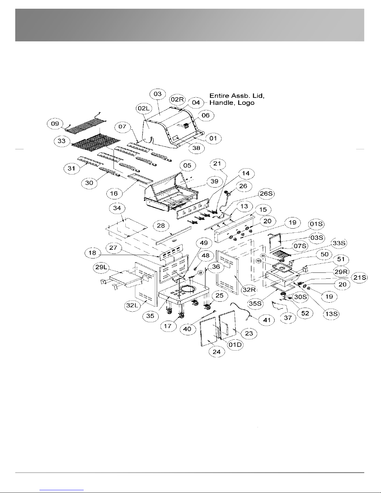
GRILL PARTS DIAGRAM
Please note: Below drawing is of the H40 grill which has four main burners and
a side burner. H30 has three burners and a right hand side shelf instead of
pictured side burner.
Notice: In our continuing effort to improve our products, we reserv e the right to make changes
to our parts and component materials at any time without notice. Please check with your PGS
dealer or AEI Corporation if you have any specific questions or concerns.
3
ASSEMBLY INSTRUCTIONS
PLEASE READ AND FOLLOW THE INSTRUCTIONS CAREFULLY
STEP BY STEP
Assembly is very simple as it primarily requires removing of carton, removing of
packaging material, attaching side shelves. Be certain to follow all steps found here-in
detailing all aspects of leak testing before attempting to light gas grill.
Tools Required:
#2 Philips head screwdriver (not provided)
Hexagon/Allen wrench (provided).
The following hardware bag is attached in left of warming rack packing foam.
Item Description Specification Quantity
Truss head screw
1
2
(With Split lock And
Gasket)
Hexagon/wrench
1/4-20x1/2” 8 pcs
1 pc
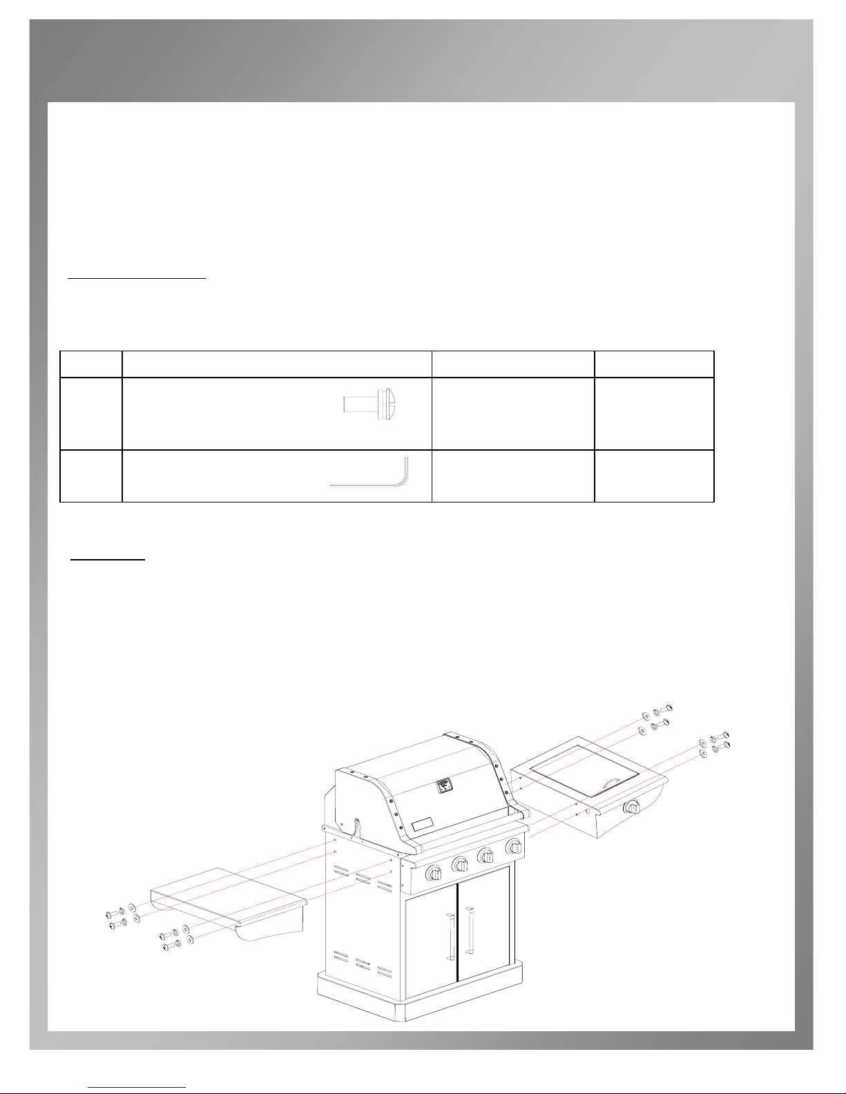
STEP I:
Carefully remove carton using caution to not scar grill with knife or blade.
Take out side shelves from carton, remove all the packing material.
Use four 1/4-20x1/2” screws to attach left side shelf to outside of the firebox.
Repeat the above step to install the right side shelf to right-hand side of the
firebox.
4
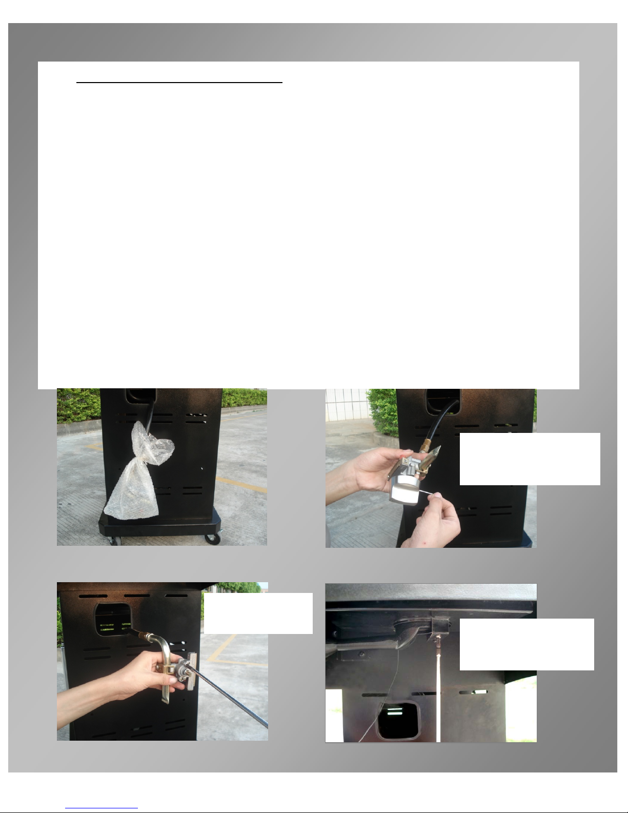
ASSEMBLY INSTRUCTIONS
• STEP II: See Images Below
VERY IMPORTANT: the knob must be removed first, otherwise
the side burner can’t be installed in next step.
1. Side Burner Hose is preassembled to gas manifold. Pull hose with side burner
valve already attached through hole in side wall of cart (square hole in right hand
panel of cart assembly).
2. Remove the packing materials. Use the provided hexagon wrench (Allen) to
loosen (don’t remove) the setscrew on the control knob, and pull out the knob.
3. Remove the two M4*6 screws from front of side burner valve.
4. Remove the two screws on side burner bracket A, which hold side burner in place,
remove side burner, to allow side valve to be mounted.
5. From underneath side shelf, place side burner valve steam to through opening on
front of side burner control panel. Attach and secure side gas valve to control
panel using the M4*6 screws.
6. Slightly insert Side Burner onto tip of gas valve make sure it’s centered. Replace
and tighten the two screws on bracket A.
7. Attach igniter wire with red sleeve to valve electrode.
8. Place and press control knob onto valve steam, and tighten the setscrew of knob.
Loosen set screw to be able
to remove knob using
provided Allen wrench-DO
NOT FULLY REMOVE Screw.
1
Remove two screws
from valve assb. Will
use again on Step #5
2
Remove two screws
securing burner in place
on Burner Bracket “A” will
use again in Step 6.
3
4
5
 Loading...