

Page 1

P. G. TM0047
electroni
El
REV. 0
electronics
Weston, Ontario
This document contains information proprietary to P.G. Electronics
and any disclosure or use of this information or any reproduction of
this document for other than the specific purpose for which it is
intended is expressly prohibited except as P.G. Electronics may
OPERATOR'S MANUAL
DUAL BAND BIDIRECTIONAL AMPLIFIER
MODEL A300
P/N 001-0300-001
RESTRICTION ON DISCLOSURE OF DATA
otherwise agree in writing.
Page 2

P. G. TM0047
GUARANTEE
This unit is guaranteed for a period of one year from the
date of shipment against failure due to defective parts or
improper assembly.
This guarantee is limited to replacement of defective
material and does not cover damages or other costs
resulting from the use of this material whether used
correctly or otherwise.
Page 3

P. G. TM0047
TABLE OF CONTENTS
Paragraph Page
SECTION 1. GENERAL INFORMATION
1.1 INTRODUCTION 1-1
1.1.1 Scope of Manual 1-1
1.1.2 Purpose of Equipment 1-1
1.1.3 Physical Description 1-1
1.1.4 Electrical Description 1-1
1.2 TECHNICAL SUMMARY 1-2
SECTION 2. THEORY OF OPERATION
2.0 GENERAL 2-1
2.1 DESCRIPTION 2-1
2.2 FAULT REPORTING 2-3
2.2.1 General 2-3
2.2.2 Report Type 2-3
2.2.3 Fault Conditions 2-3
SECTION 3. INSTALLATION, OPERATING AND MAINTENANCE
INSTRUCTIONS
3.1 UNPACKING AND INSPECTION 3-1
3.2 INSTALLATION 3-2
3.3 OPERATING INSTRUCTIONS 3-4
3.4 FAULT CONDITIONS 3-4
SECTION 4. PROGRAMMING OPTIONS
4.0 PROGRAMMING OPTIONS 4-1
4.1 DC CONTINUITY 4-1
4.2 ATTENUATION 4-1
4.3 FAULT OPTIONS 4-2
4.4 STATUS OPTIONS 4-4
4.5 TEST 4-4
4.6 FAULT CODE 4-4
i
Page 4

P. G. TM0047
LIST OF FIGURES
Figure Title Page
2-1 A300 Bidirectional Amplifier – Block Diagram 2-2
3-1 Installation Data 3-3
4-1 A300 Programming Options-Jumper Locations 4-3
4-2 Fault Code Setting Examples 4-5
A-1 Autoset Shunt Position A-3
LIST OF TABLES
Table Title Page
1-1 Performance Characteristics and Salient Features of 1-2
the A300 SMR/PCS Bidirectional Amplifier
1-2 Rated Power Output for Linear Operation 1-3
A-1 Shunt Installation A-4
APPENDIX A
A AUTOSET ATTENUATION OPTION (IF INSTALLED) A-1
A-1 GENERAL A-2
A-2 INSTALLATION A-2
A-3 OPERATION A-2
ii
Page 5

P. G. TM0047
SECTION 1. GENERAL INFORMATION
1. INTRODUCTION
1.1.1 Scope of Manual - This manual is intended to familiarize service personnel
working on the Dual Band Bidirectional Amplifier A300 with all pertinent aspects of the
amplifier. Included in this manual are a brief physical description, a technical summary,
installation information and operating data.
1.1.2 Purpose of Equipment - The A300 amplifier is used as a drop-in booster for
SMR (800 MHz trunking) and PCS signals carried on 50 ohm coax cable. The amplifier
will simultanously amplify signals in the SMR and PCS transmit bands in one direction
and the SMR and PCS receive bands in the opposite direction. A typical use of the
A300 is to provide SMR and PCS phone coverage in underground installations.
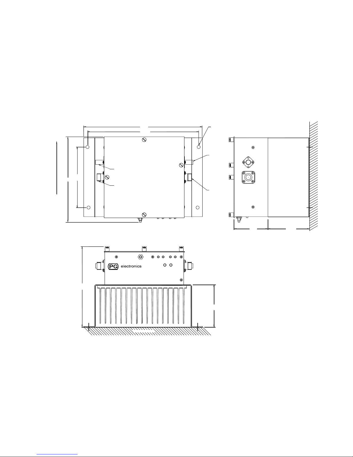
1.1.3 Physical Description - The bidirectional amplifier, shown in Figure 3-1, is
designed to be mounted on a flat vertical surface. The unit has two N connectors for
connection to the distribution cable and two BNC test ports to check RF signals. A 5-pin
DIN receptacle is provided for local power source connection. Color coded indicators
provide visual display of the unit's operating status.
1.1.4 Electrical Description - The bidirectional amplifier provides approximately 20
dB of gain for signals in the 804 - 824 MHz and 1850 - 1910 MHz bands in the direction
of J1 to J2 (antenna to base) and the same amount of gain for signals in the 850 - 870
MHz and 1930 - 1990 MHz bands in the opposite direction (J2 to J1).
1.1.4.1. - The unit is locally powered through a 5-pin DIN receptacle. The P.G.
Electronics PS293 power source should be used to power the unit. The unit provides
DC continuity from J1 to J2 to allow powering of downstream amplifiers from upstream
power sources such as PS212 and PS213. Local power is isolated from J1 and J2.
1.1.4.2.
monitors downlink power in both bands. If one of these devices draws more or less than
a predetermined limit, or if the RF downlink power is low then the FAULT indicator will
go on. Under normal operating condition only the green NORMAL indicator will be on.
1.1.4.3. - If a FAULT condition is detected the unit transmits a low frequency
identification code along the cable center conductor. The burst transmission is repeated
at approximately 80 second intervals, while a fault condition exists. The fault reporting
circuitry is powered from the cable.
1.1.4.4 - If a NORMAL condition exists in the amplifier a low frequency OK identification
code will be transmitted on the cable at intervals of approximately 80 minutes.
1.1.4.5 – The unit has an adjustable attenuator in each band to allow operation at
reduced gain. The attenuator is settable in 1 dB steps up to 15 dB either manually or by
using an optional AUTOSET control board.
- The unit monitors bias conditions of active devices in the RF path and
1-1
Page 6

P. G. TM0047
1.2 TECHNICAL SUMMARY
TABLE 1-1
Performance Characteristics and
Salient Features of the A300 SMR/PCS Bidirectional Amplifier
Parameter Specification
1. Input Power: 24 - 28 VDC @ 3 A Max.
(use PS293)
SMR PCS
2. Frequency Range*: Uplink: Downlink: Uplink: Downlink:
(MHz) 804-824 850-870 1850-1910 1930-1990
3. Gain: 20dB ±1.5dB
4. Impedance 50 Ohms
5. VSWR 2:1 Typical, 3:1 Maximum
SMR PCS
6. Composite Output Uplink: Downlink: Uplink: Downlink:
Power Rating** (dBm) +9 +24 +4 +24
7. Output 1dB Uplink: Downlink: Uplink: Downlink:
Compression Point (dBm) +17 +33 +12 +33
8. 3rd Order Output Uplink: Downlink: Uplink: Downlink:
Intercept Point (dBm) +32 +45 +27 +45
9. Attenuator Range 0 to 15 dB in 1 dB steps (in each band)
10. Environmental Limits (a) Temperature Range: -30°C to 60°C operating
(b) Relative Humidity: to 90%
11. Dimensions and Weight
(a) Overall Dimensions: 9.8”(249mm) L x 6.7”(170mm) W x 6.7”(170mm) H
(b) Mounting Hole Dims: 9.0”(229mm) x 5.0”(127mm)
(c) Weight: 6.0. lb (2.7 kg)
12. Connectors:
RF Input/Output Type N Female
RF Test Input/Output Type BNC Female
DC supply 5-pin DIN receptacle
NOTES: * Specifications apply only across the customers actual bands, not across
the whole PCS spectrum.
** Refer to Table 1-2 for definition of composite output power rating.
1-2
Page 7

P. G. TM0047
NOTE IMPORTANT RATING INFORMATION
Manufacturer’s rated output power of this equipment is for single
carrier operation. For situations when multiple carrier signals are
present, the rating would have to be reduced as per Table 1-2,
especially where the output signal is re-radiated and can cause
interference to adjacent band users. This output power reduction is to
be achieved by reduction of input power or by gain reduction and not
by an attenuator at the output of the device.
TABLE 1-2
Rated Power Output for Linear Operation
The total composite output power in multiple tone or wideband signals shall NOT exceed
the following level or else it may result in improper operation of the device and cause
interference. The composite output power rating is defined as the total average RMS
output power of all inband signals. The unit should be operated at or below this level to
ensure linear operation with low distortion. This holds true for any number of carriers
with total average power adding up to the composite output power rating listed in the
table below.
SMR Base Transmit (Downlink) +24 dBm
SMR Portable Transmit (Uplink): +9 dBm
PCS Base Transmit (Downlink): +24dBm
PCS Portable Transmit (Uplink): +4dBm
1-3
Page 8

P. G. TM0047
SECTION 2. THEORY OF OPERATION
2.0 GENERAL
As explained in Section 1, the A300 is a bidirectional amplifier, which provides 20 dB of
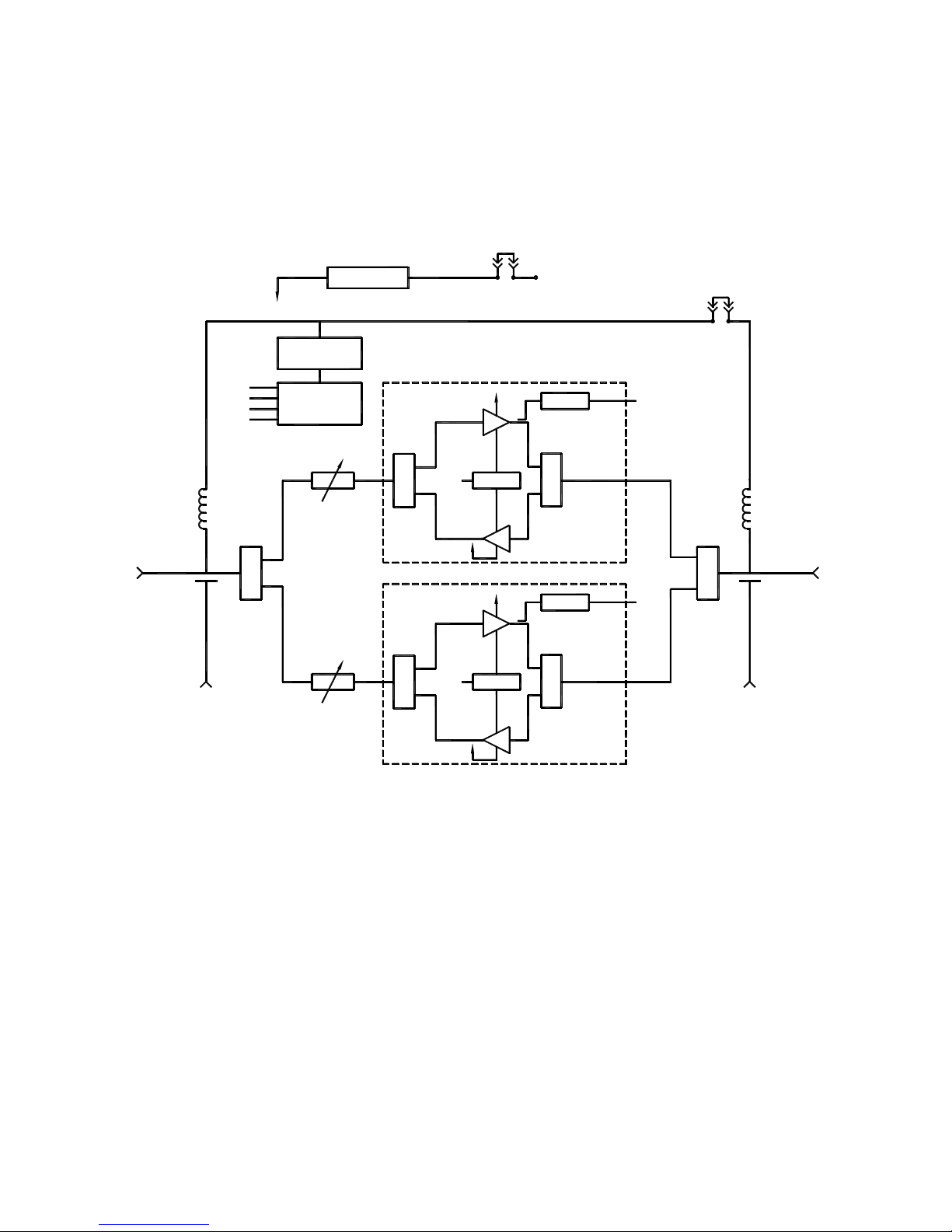
gain in both the SMR and PCS wireless transmit and receive bands. The block diagram
of the amplifier is shown in Figure 2-1.
2.1 DESCRIPTION
2.1.1 - The unit is composed of two diplexers, two independent bidirectional amplifiers
and alarm and voltage regulation circuits.
2.1.2 - The diplexers U1 and U2 divide power between the SMR and PCS bidirectional
amplifiers. In each bidirectional amplifier additional bandpass diplexers separate signals
for the uplink and downlink amplifiers.
2.1.3 - The bias condition of devices in the amplifiers is monitored. If the bias changes
outside certain limits a fault condition is indicated. The downlink RF output power in
each band is also monitored. If the power in either band drops below established limits
a FAULT condition is indicated.
When a FAULT condition occurs the unit transmits the unit identification (or "Fault
Code") by two level amplitude modulation of a low frequency carrier placed on the cable
center conductor. The signal is transmitted as a short burst repeated at approximately
80 second intervals while the fault condition persists. The fault code can be
reprogrammed as described in Section 3.2. While a NORMAL condition exists the
amplifier transmits an OK code at intervals of approximately 80 minutes.
2.1.4 - The voltage regulators take 24 - 28 VDC input and provide 20 VDC and 12 VDC
outputs. A zener diode provides transient protection against voltage spikes on the cable.
2.1.5 - The A300 dual band bidirectional amplifier requires external DC power to be
supplied through the 5-pin DIN receptacle. The unit should be powered locally by the
PS293 external power source. The local power source is isolated from J1 and J2.
The unit provides DC continuity from J1 to J2 to allow downstream cable powered
amplifiers to receive their power from upstream power sources such as the PS212 and
PS213. In addition, status signals from downstream cable powered amplifiers are
passed through the amplifier from J1 to J2.
2-1
Page 9
P. G. TM0047
J2
BASE
REGULATION
+
ALARM
TRANSMITTER
CRF
CB
PB
PRF
U2 U1
J4
TEST
ALARM
DETECTION
SMR
ATTENUATOR
PCS
ATTENUATOR
SMR AMPLIFIER
CB
SENSOR
+
PB
SENSOR
+
EXT DC
SENSOR CRF
800 MHz
SENSOR
1900 MHz
PRF
DCJ1-DCJ2
J1
DISTRIBUTION
ANTENNA
J3
TEST
Figure 2-1. A300 Bidirectional Amplifier - Block Diagram
PCS AMPLIFIER
2-2
Page 10

P. G. TM0047
2.2 FAULT REPORTING
2.2.1 General - The amplifier incorporates a number of circuits to detect deviations in
important performance parameters. The unit reports alarm conditions to a remote
Monitor unit such as the Model PS212.
The various functions are described in this section and may also be referenced in
Section 4 where the programming of amplifier options is discussed.
2.2.2 Report Types - The unit generates two types of reports depending on the status
of the amplifier as determined by the built in monitor circuits. Each type consists of a
numeric code sent as low frequency tones along the coaxial cable for decoding at the
monitor unit.
Under normal operation the unit will transmit an "OK" code at intervals of approximately
80 minutes. This enables the system monitoring unit to keep track that the whole
system is connected and operational. In this mode a local green NORMAL LED lamp is
illuminated on the side of the amplifier.
In the event that a fault is detected in the amplifier, as described later, a "FAULT" code
is transmitted on the cable at intervals of approximately 80 seconds. In this mode a
local red FAULT LED is illuminated on the amplifier. Four LEDs on the side of the unit
indicate which specific local condition is causing the overall FAULT condition as
described in the next section.
In each case the code transmitted identifies the transmitting amplifier by the FAULT
CODE programmed in that particular amplifier as described later in Section 4.6. Before
shipment P.G. programs each amplifier with an arbitrary code from 1 to 199 which is
also shown by a label on the outside of the unit.
NOTE: - Older models of P.G. bidirectional amplifiers such as the A181 or A188
transmitted only fault codes, but are compatible with the fault codes transmitted
by the A300. When used with a PS212 Monitor, the A181 or A188 codes
should be entered in the ID list as "FAULT ONLY" (TFO) type units. If the A300
is used with a PS200 PS/Monitor the OK code transmission (STATUS option)
should be disabled (section 4.4) as it will cause the PS200 to display a FAULT
alarm. Fault codes above 199 should not be set on any amplifiers since they
may be incorrectly interpreted by the newer PS212.
2.2.3 Fault Conditions - The A300 circuitry monitors four separate parameters in
the unit. These are (a) the bias currents drawn by devices in both the amplifiers and (b)
the presence of downlink RF output power in each band. Each function can be disabled
as described in Section 4, if the unit is being used in a restricted operational mode.
2-3
Page 11

P. G. TM0047
The DC current monitoring triggers a fault condition if DC bias current deviates outside
predetermined high or low current limits.
The downlink RF output power from each frequency band is monitored by separate
detectors and a FAULT condition is triggered if the level in either band drops below a
nominal level of + 5 dBm. If the amplifier is to be installed at a point in the system where
the output power in either band may be less than +7 dBm then the RF monitor circuit for
the appropriate band should be disabled as described in Section 4 herein.
The local fault indicators indicate specific faults as follows:
SMR
BIAS Bias fault in the SMR amplifier
PWR Low downlink RF power from the SMR amplifier
PCS
BIAS Bias fault in the PCS amplifier
PWR Low downlink RF power from the PCS amplifier
NOTE: There is a certain situation in which the red “FAULT” indicator will be on even
though none of the cellular or PCS “BIAS” or ‘PWR” indicators are on. This
situation occurs when the unit is receiving local power and downlink RF powers
are normal but the cable power is not present. This indicates that the cable
power source located upstream has been switched off or has shut down.
2-4
Page 12

P. G. TM0047
SECTION 3. INSTALLATION, OPERATING AND MAINTENANCE
INSTRUCTIONS
3.1 UNPACKING AND INSPECTION
The following checks are recommended after receipt of the equipment from shipping
agent:
1. Check for any external damage that could have occurred in transit. If damage is
found, report to the shipping agent and to the supplier immediately.
2. Check that all items on the packing slip are present. If any are missing, report to
the supplier immediately.
3. The amplifiers all have been programmed at the factory with the following
settings.
DC Continuity: - J1 and J2 both connected for through power.
Alarm options: - Bias and RF engaged for both bands.
Alarm Code: - Consecutive numbers assigned.
(Check for duplication if two lots used).
Attenuation: - -Set to zero attenuation in both bands if autoset board not
installed.
It is suggested that known changes required to these settings be made on the
bench before the units are installed at the site. Consult section 4.0 for more
information on this task.
3-1
Page 13

P. G. TM0047
3.2 INSTALLATION
The bidirectional amplifier is designed for mounting on a flat vertical surface The unit is
mounted with the indicator side down for adequate air circulation. Proceed as follows:
1. Locate a suitable mounting location, allow a clearance of at least 5 inches (13 cm) to
route mating cable and connectors to the unit. Drill four pilot holes on 9 x 5 inch
centers for No.10 fasteners.
2. Mount the amplifier ensuring there is good air circulation around the amplifier.
3. Connect J2, "BASE" to the cable leading to the base transmitter.
4. Connect J1, "ANTENNA" to the cable leading to the distribution antenna(s).
If it is known that the programming has been correctly preset as required by the
system plan then this completes the installation. It is recommended the alarm code,
alarm option settings and attenuation settings for each amplifier be recorded on the
system "as-built" drawing. Otherwise perform the steps below as required.
5. If DC continuity, attenuation, alarm options or alarm code must be changed, remove
the cover plate from the amplifier to provide access to the programming jumpers.
NOTE: Section 4.0 of this manual describes programming details. For convenience
a reduced size copy of diagram Figure 4-1 is provided on the inside of the amplifier
cover as a reference.
6. If the unit is NOT required to pass DC down the line to another amplifier then it is
recommended that the DC jumper to J1 be removed to provide DC isolation at J1.
See Section 4.1.
7. If certain fault alarms should be disabled then reprogram the appropriate jumpers as
described in Section 4.3.
8. If it is required to change the factory set alarm code then program the appropriate
jumpers as described in Section 4.6.
9. If the SMR and/or PCS attenuators must be set then refer to section 4.2. If the
optional AUTOSET control board is fitted, skip this step.
10. Replace the amplifier cover. NOTE: It must be correctly oriented to fit properly.
This completes the installation.
3-2
Page 14
P. G. TM0047
MOUNT IN
THIS
DIRECTION
TO ALLOW
AIR FLOW.
7.07
5.00
J3
TAP
J1
ANTENNA
FSCM 38243
MODEL A300
P/N 001-0300-001
S/N
9.80
9.00
FRONT VIEW
FAULT TEST
STATUS
SMR
PWR
BIAS
BIAS
NORMAL
FAULT CODE 00 0
MADE IN CANADA
PCS
FAULT
PWR
0.265" DIA
(4 MOUNTING HOLES)
BNC
FEMALE
(2 PLACES)
N
FEMALE
(2 PLACES)
-30dB 850 MHz
-24dB 1.9 GHz
J4
TAP
J2
BASE
RIGHT SIDE VIEW
VERTICA L WALL
VERTICAL WALL
BOTTOM VIEW
Figure 3-1. Installation Data
3-3
Page 15

P. G. TM0047
3.3 OPERATING INSTRUCTIONS
The A300 dual band bidirectional amplifier has no external controls. When powered the
unit will amplify signals in each band and in each direction.
When the green light is on, bias conditions of active devices in the RF paths are within
specifications and the downlink power in each band is above the minimum preset limit.
The red FAULT light goes on whenever a monitored active device in the RF paths has
failed or the downlink output power is too low. Corrective action is to check if the input
power in each band is correct and then to check the fault conditions as indicated below.
3.4 FAULT CONDITIONS
If the FAULT light is illuminated it indicates that one of the following conditions have
occurred. Four LEDs on the side of the unit show the status of the RF and DC bias
alarms and indicate the source of the fault conditions.
3.4.1 Low RF power (“PWR” LED on) - Check the level of RF power out of the
amplifier by connecting a meter or spectrum analyzer to the Test Port J3. The actual
level is higher than the measured level by 30 dB at SMR and 24 dB at PCS frequencies.
If the RF fault option is enabled a fault will occur if the RF power in either band falls
below approximately +5 dBm.
By measuring the RF input power at J4 the correct functioning of the amplifier can be
checked. The gain should be approximately 20 dB minus the inserted attenuation.
3.4.2 DC Bias Change (“BIAS” LED on) - A DC bias alarm indicates a fault in the
amplifier for the particular frequency band indicated. This condition mandates
replacement of the amplifier except as noted below.
NOTE: - The SMR uplink amplifier will show a DC bias alarm if the amplifier is driven
into saturation by excessive RF power levels. A true DC bias fault will persist when RF
carriers have been reduced in level.
3-4
Page 16

P. G. TM0047
SECTION 4. PROGRAMMING OPTIONS
4.0 PROGRAMMING OPTIONS
The amplifier contains a number of options which are programmed before the unit is
installed, or may be adjusted during system installation or modification. They are set in
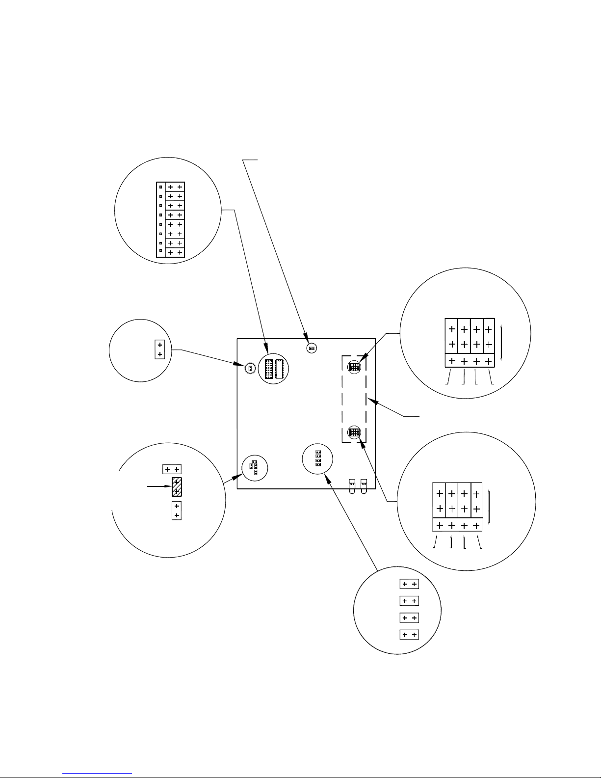
a default setting by PG before shipment. A summary diagram of these jumpers is
affixed to the inside of the removable amplifier cover for use in the field, but a larger view
is shown herein (Fig 4-1) together with the following description of these settings.
It is suggested that when jumpers are removed to break a circuit, that they be reinstalled
on one pin at the same location to keep them readily available if the option is reselected
at a later date.
4.1 DC CONTINUITY (DC)
A DC jumper is provided to permit the amplifier to isolate J1 from DC if there is NO need
for downstream power and particularly if a DC grounded device is installed in series with
the amplifier. Removing the jumper breaks the DC connection from connector J2 to J1,
and is recommended practice.
The jumper is labelled “DCJ1 DCJ2”. The jumper provides DC continuity to the J1 and
J2 connectors. The “EX” is used to provide connection from the local power DC
receptacle to power the amplifier. The “EX” jumper should always be installed.
NOTE: Breaking the DC connection also disconnects the low frequency FAULT code
from being transmitted along the cable from a downlink amplifier or power
supply.
4.2 ATTENUATION (AC AND AP)
The A300 amplifier has a nominal overall gain of 20 dB in both the SMR and the PCS
frequency bands, but this gain may be reduced by built-in attenuators included in each
frequency band. The attenuators are installed on the uplink side of the amplifier and
hence do not have significant impact on the uplink system noise figure.
The attenuator for each band is set for values from 0 to 15 dB by four jumpers in a
binary sequence. Setting the jumpers to the “IN” position inserts, 1, 2, 4 or 8 dB
attenuation in the circuit for that band. Refer to the label attached to the inside of the
cover for an enlarged view of these jumpers and their setting positions.
NOTE: The jumpers must be set to either the IN or OUT positions for correct attenuator
operation. Do not leave open. If the optional AUTOSET control board is fitted,
see Appendix A for further information.
4-1
Page 17

P. G. TM0047
4.3. FAULT OPTIONS (F)
The block of four jumpers for the fault options allows disabling of each of four tests by
removing the appropriate jumper.
The jumpers to monitor downlink RF power are labelled CRF for the SMR band and PRF
for the PCS band.
The jumpers to disable amplifier bias current monitoring are labelled CB for the SMR
amplifier and PB for the PCS amplifier.
4-2
Page 18
P. G. TM0047
ALARM CODE (SEE HANDBOOK)
BINARY CODE IN
THIS EXAMPLE IS ZERO
CODE
H
0
1
2
3
4
5
6
7
STATUS REPORTS
(OPEN DISABLES
OK REPORTS)
/
FOR PG TEST USE ONLY
OPEN FOR
NORMAL OPERATION
CELL
ATTN
|8|4|2|1|
SMR BAND
ATTENUATOR
OUT
STATUS
DC CONTINUITY
(OPEN REMOVES DC)
DCJ2DCJ1
IMPORTANT
LEAVE OPEN
PG TEST ONLY
EXT. DC IN
EX
ALARMS ON/OFF
(OPEN TO DISABLE)
PCS RF OUT
SMR RF OUT
PCS AMP BIAS
SMR AMP BIAS
PRF
CRF
PB
CB
4dB
8dB
2dB
AUTOSET OPTION
PCS BAND
8dB
ATTENUATO R
4dB
2dB
OUT
,1
1dB
IN
1dB
PCS
ATTN
|8|4|2|1|
Figure 4-1. A300 Programming Options - Jumper Locations
4-3
Page 19

P. G. TM0047
4.4 STATUS OPTION (S)
If it is desired to use the amplifier in a system that has "Fault only" monitoring such as is
provided by the PS200 unit, then the "OK" reports may be disabled by removing the
STATUS jumper.
4.5 TEST (T)
The test jumper location does not have any function in normal system operation. It is
provided for use in FAT testing in the factory by speeding up the rate of OK code
reporting. It should be open for normal operation.
4.6 FAULT CODE (C)
If it is required to change the factory set Fault Code to the operator's custom plan then
follow the following steps:
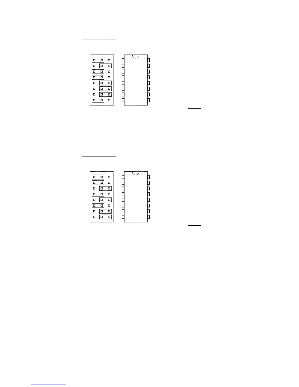
1. Refer to the jumper field with a block of eight jumpers labelled 0 to 7 in Figures 4-1
and 4-2.
2. The code is programmable in binary with the numbers 0 to 7 representing the
power of 2, i.e., the jumper is 23 = 8. When the jumper is on the H side the count is
included. When the jumper is on the L side the count is zero for that binary digit.
3. Before reprogramming check the examples, Figure 4-2, and examine the factory
set code as a starting point.
NOTE: The center pin “C” MUST be jumpered to EITHER the “H” or “L” side for a
correct code to be sent. Do not leave open.
4-4
Page 20
P. G. TM0047
EXAMPLE 1:
H L
0
1
2
3
U12
4
5
6
7
H = HIGH OR IN
L = LOW OR OUT
EXAMPLE 2:
H L
0
1
2
3
U12
4
5
6
7
0
2 x 1 = 1
1
2 x 0 = 0
2
2 x 1 = 4
3
2 x 1 = 8
4
2 x 0 = 0
5
2 x 0 = 0
6
2 x 0 = 0
7
2 x 1 = 128
code = 141
0
2 x 1 = 1
1
2 x 1 = 2
2
2 x 0 = 0
3
2 x 1 = 8
4
2 x 0 = 0
5
2 x 1 = 32
6
2 x 0 = 0
7
2 x 0 = 0
code = 43
H = HIGH OR IN
L = LOW OR OUT
NOTE: DO NOT SET FAULT CODE ABOVE 199.
FAULT CODES ABOVE 199 ARE RESERVED
Figure 4-2. Fault Code Setting Examples
4-5
Page 21

P. G. TM0047
APPENDIX A
AUTOSET ATTENUATION OPTION
(IF INSTALLED)
A-1
Page 22

P. G. TM0047
A-1 GENERAL
The AUTOSET optional gain control board installs on the jumper pins normally used for
manual setting of the gain control attenuators referred to in Paragraph 4.2.
When installed the AUTOSET board automatically limits the amplifier output power to
the maximum composite level compatible with low intermodulation performance.
A-2 INSTALLATION
The AUTOSET board has four jumpers which are set depending on whether the
amplifier is being used as an IN-LINE or ANTENNA amplifier. An IN-LINE amplifier
normally passes power to downlink amplifiers and is set to a slightly lower power level to
minimize cascading of IM products. The jumpers are set in accordance with Figure
A-1.
A-3 OPERATION
The AUTOSET controls each individual amplifier on a stand-alone basis. The
AUTOSET system has two modes of operation.
When initially powered the AUTOSET goes into an AGC mode where it tracks the
composite output power and adjusts the attenuator to maintain maximum output power.
This mode continues for approximately 90 minutes until the system achieves
temperature stability.
At this point the AUTOSET switches to a LIMITER mode in which it only adds
attenuation if the power input increases above the final setting value. This eliminates
the system hunting which might interact with system power control or cause near/far loss
of signal.
If however power in the systems is increased by the addition of more channels the gain
will adjust downward to avoid distortion products.
The AUTOSET system can be configured to operate in a continuous AGC mode by
installing the “AM” shunt. In this mode, the AUTOSET operates in AGC mode
indefinitely and will not switch to a LIMITER mode.
Each time the system (or amplifier) is repowered the setting cycle is repeated.
A-2
Page 23
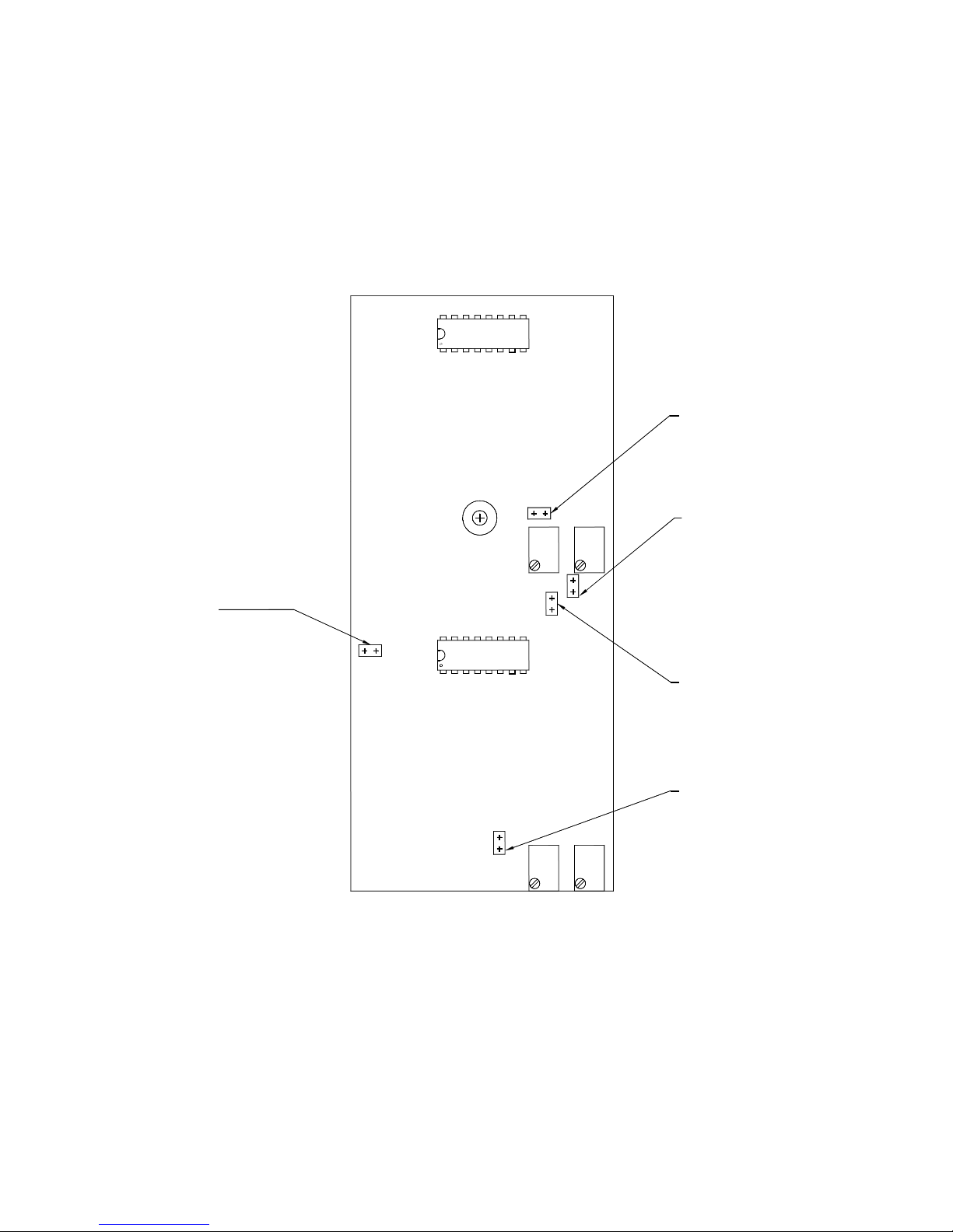
P. G. TM0047
AUTOSET SHUNT POSITIONS
SHUNT
CI
INSTALLED FOR INLINE AMP
REMOVED FO R AN TENNA AM P
CI
SHUNT
AM
REMOVED FOR STANDARD
(TIMED) AGC MODE
INSTALLED FOR
CONTINUOUS AGC MODE
SS
SHUNT
INSTALLED FOR INLINE AMP
REMO VED FOR ANTENN A AMP
AM
AS
SS
PI
Figure A-1. Autoset Shunt Positions.
SHUNT
AS
REMOVED FO R INLINE AM P
INSTALLED FOR ANTENNA AMP
SHUNT
PI
INSTALLED FOR INLINE AMP
REMOVED FO R AN TENNA AM P
A-3
Page 24

P. G. TM0047
TABLE A-1
Shunt Installation
UNIT TYPE SHUNT
DCJ1 DCJ2
CI
INLINE AMPLIFIER I R I I I
ANTENNA AMPLIFIER R I R R R
Note: I = Shunt installed
R = Shunt removed
AS PI SS (Mainboard)
A-4
 Loading...