

Page 1

P.G. TM0026AE
electronics
OPERATOR'S MANUAL
PCS REPEATER
MODEL R231
P/N 001-0231-001
MARCH 2002
This document contains information proprietary to P.G. Electronics and any
disclosure or use of this information or any reproduction of this document for
other than the specific purpose for which it is intended is expressly prohibited
RESTRICTION ON DISCLOSURE OF DATA
except as P.G. Electronics may otherwise agree in writing.
Page 2

P.G. TM0026AE
GUARANTEE
This unit is guaranteed for a period of one year from
the date of shipment against failure due to defective
parts or improper assembly.
This guarantee is limited to replacement of defective
material and does not cover damages or other costs
resulting from the use of this material whether used
correctly or otherwise.
i
Page 3

P.G. TM0026AE
TABLE OF CONTENTS
Paragraph
Page
SECTION 1. GENERAL INFORMATION
1.1 INTRODUCTION 1-1
1.1.1 Scope of Manual 1-2
1.1.2 Purpose of Equipment 1-3
1.1.3 Physical Description 1-3
1.1.4 Electrical Description 1-3
1.2 TECHNICAL SUMMARY 1-3
SECTION 2. INSTALLATION, OPERATING AND MAINTENANCE INSTRUCTIONS
2.1 UNPACKING AND INSPECTION 2-1
2.2 INSTALLATION 2-1
2.3 OPERATING INSTRUCTIONS 2-1
ii
Page 4

P.G. TM0026AE
LIST OF FIGURES
Figure
Title Page
2-1 Installation Data 2-2
LIST OF TABLES
Title Page
Table
1-1 Performance Characteristics and Salient Features of the 1-2
R231 PCS Repeater
1-2 Rated Power Output for Linear Operation 1-3
iii
Page 5

P.G. TM0026AE
SECTION 1. GENERAL INFORMATION
1.1 INTRODUCTION
1.1.1 Scope of Manual.
- This manual is intended to familiarize personnel installing the R231 PCS
Repeater with all pertinent aspects of the amplifier. Included in this manual are a brief physical
description, a technical summary, installation and operating data.
1.1.2 Purpose of Equipment.
- The R231 Repeater is used as a drop-in booster for PCS signals. It will
simultaneously amplify signals in the PCS transmit band in one direction and the PCS receive band in
the opposite direction. A typical use of the R231 is to provide PCS phone coverage in enclosed areas.
1.1.3 Physical Description.
- The unit, shown in Figure 3-1, is designed to be mounted on a flat surface.
The unit has two N connectors for antenna connections. Four color coded indicators provide visual
display of the unit's operating status.
1.1.4 Electrical Description.
- The unit provides approximately 43 dB of gain for signals in the 1850 1910 MHz band in the direction of J1 to J2 (distribution to base) and the same amount of gain for signal
in the 1930 - 1990 MHz band in the opposite direction (J2 to J1).
1.1.4.1.
- An AC-DC external power source is used to provide power via a power jack on the unit.
1.1.4.2.
- The unit monitors bias conditions of all active devices in the RF path. Under normal operating
condition the green indicators will be on. If one of these devices draws more or less than a
predetermined limit then a red indicator will go on.
1.2 TECHNICAL SUMMARY
The power requirements, performance characteristics and dimensions and weight of the R231 Repeater
are summarized in Table 1-1.
1-1
Page 6

P.G. TM0026AE
TABLE 1-1. Performance Characteristics and
Salient Features of the R231 PCS Repeater
Parameter Specification
1. Input Power: 15 to 32 VDC @ 500 mA Max.
2. Frequency Range:
- Base Receive (Uplink) 1851MHz to 1909 MHz
- Base Transmit (Downlink) 1931 MHz to 1989 MHz
3. Rated RF Input: -32 dBm Maximum (single channel)
Note: The following specifications apply in both directions
4. Gain: 43 dB ±3 dB
5. Impedance (Input and Output): 50 Ohms
6. VSWR: 2:1 Typical
7. Rated Output Power: +12 dBm Typical (1 signal)
rd
8. 3
Order Output IP: +30 dBm Typical
9. Environmental Limits
(a) Ambient Temperature Range: -30°C to 60°C Operating
(b) Ambient Relative Humidity: Up to 90%
10. Dimensions:
(a) Enclosure Dimensions: 10” L x 9.1” W x 2” H
254.0mm L x 231.6mm W x 50.8mm H
(b) Mounting Holes Dimensions: 8.4” x 8.0” (213.4mm x 203.2mm)
(c) Weight: 2.0 Lbs (0.9 Kg)
11. Connections:
RF Input/Output: Type N Female
DC Supply: DC Power Jack
NOTE: Specifications apply only across the customer’s actual bands,
not across the whole PCS spectrum.
1-2
Page 7

P.G. TM0026AE
NOTE IMPORTANT RATING INFORMATION
Manufacturer’s rated output power of this equipment if for single carrier
operation. For situations when multiple carrier signals are present, the
rating would have to be reduced as per Table 1-2, especially where the
output signal is re-radiated and can cause interference to adjacent
band users. This output power reduction is to be achieved by
reduction of input power.
TABLE 1-2 Rated Power Output for Linear Operation
(for intermodulation products 50 dB down)
The Total Composite output power in multiple tone or wideband signals shall NOT exceed the
following level or else it may result in improper operation of the device and cause interference.
Parameter Specification
Base Transmit (Downlink) Power: +6 dBm
Portable Transmit (Uplink) Power: +6 dBm
1-3
Page 8

P.G. TM0026AE
SECTION 2. INSTALLATION, OPERATING AND MAINTENANCE INSTRUCTIONS
2.1 UNPACKING AND INSPECTION
The following checks are recommended after receipt of the equipment from shipping agent:
1. Check for any external damage that could have occurred in transit. If damage is found, report
to the shipping agent and to the supplier immediately.
2. Check that all items on the packing slip are present. If any are missing, report to the supplier
immediately.
2.2 INSTALLATION
The Repeater is designed for mounting on a flat surface. The unit can be mounted in any orientation as
desired although it is practical to select a mounting position which allows the indicators to be seen.
Proceed as follows:
1. Locate a suitable mounting location, allow a clearance of at least 5 inches (13 cm) to route
mating cable and connectors to the unit. Drill four pilot holes on a 8.4 x 8 inch center for No.10
fasteners.
2. Connect J2, "BASE ANTENNA" to the cable leading to the base antenna.
3. Connect J1, "DISTRIBUTION ANTENNA" to the cable leading to the distribution antenna(s).
4. Connect the external DC power source to the DC input. The unit may be powered by DC
voltages in the range of 15-32 V. The unit is typically powered with the P.G. Electronics PS217
18 VDC adapter.
2.3 OPERATING INSTRUCTIONS
The R231 PCS Repeater has no internal or external controls. When powered the unit will amplify
signals in both the uplink and downlink bands.
When the green light is on, bias conditions of active devices in the RF paths are within specifications.
The red light goes on whenever any active device in the RF path has failed. Corrective action is to
service the amplifier.
2-1
Page 9
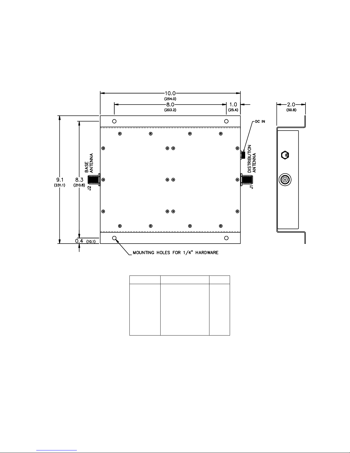
P.G. TM0026AE
CONNECTOR
REFERENCE
J1
J2
DC IN
SIGNAL
DESCRIPTION
BASE RECEIVE INPUT
(UPLINK)
BASE TRANSMIT
OUTPUT
(DOWNLINK)
BASE TRANSMIT INPUT
(DOWNLINK)
BASE RECEIVE OUTPUT
(UPLINK)
15-32 VDC INPUT
Figure 2-1. Installation Data
2-2
TYPE
N
N
POWER
JACK
 Loading...