


Inhaltsverzeichnis
2017-08-07
Operating Manual
PFT SCREW MIXER HM 24
Part 2, EC Declaration of Conformity
Overview – Operation – Spare Parts Lists
Article number of operating instructions:
00 01 20 81
HM 24, 400V, 3 phases 60Hz item number 00211876
HM 24, 400 V, 3 phases 60 Hz with AV 1000 and rubber mixing tube item number 00508157
HM 24, 400 V, 3 phases 50 Hz item number 00007874
HM 24, 230 V, 3 phases 60 Hz with rubber mixing tube item number 00265323
HM 24, 400 V, 3 phases 50 Hz with rubber mixing tube item number 00020357
HM 24, 400V with separate mortar outlet flange and dosing shaft 35 l/min item number 00008783
HM 24, 400V, 3 phase, 50Hz with control box for level probe and vibrators item number 00036940
HM 24, 400V, rubber mixing tube / control box / water pressure booster pump item number 00070219
HM 24, 400V, rubber mixing tube, control box, water pressure booster pump item number 00463945
Please read the operating instructions before starting work!

© Knauf PFT GmbH & Co. KG
Postfach 60 97343 Iphofen
Einersheimer Straße 53 97346 Iphofen
Deutschland
Telefon +49 9323 31-760
Telefax +49 9323 31-770
Technische Hotline +49 9323 31-1818
info@pft-iphofen.de
www.pft.eu
2
2017-08-07

PFT SCREW MIXER HM 24 Overview – Operation – Spare Parts Lists
Table of Contents
1 EC Declaration of Conformity ..................... 5
2 Testing .......................................................... 6
2.1 Testing by machine operator ............... 6
2.2 Periodic inspection .............................. 6
3 General notes ............................................... 7
3.1 Information about operating
instructions........................................... 7
3.2 Please retain the instructions for
later use ............................................... 7
3.3 Division ................................................ 7
4 Technical data .............................................. 8
4.1 General specifications ......................... 8
4.2 Electrical 400V ..................................... 8
4.3 Operating conditions ............................ 8
4.4 Noise level ........................................... 8
4.5 Vibrations ............................................. 8
5 Overview HM 24 ........................................... 9
5.1 Water Manifold................................... 10
5.2 Water Manifold with Water pressure
booster pump ..................................... 10
6 Type plate ................................................... 11
7 Quality control sticker ............................... 11
8 Connections ............................................... 11
8.1 Connection without control box 400V 11
8.2 Connection with control box 400V ..... 11
8.3 Connection without control box 230V 12
8.4 Connection HM 24 with control box ... 12
9 Description of Functions .......................... 13
10 Basic Saftey Instructions .......................... 14
11 Safety rules ................................................. 15
12 Transport, packing and storage ............... 15
12.1 Safety instructions for transport ......... 15
12.2 Transport inspection .......................... 16
13 Packaging ................................................... 16
14 Operation ..................................................... 17
14.1 Safety ................................................. 17
15 Preparing the machine ............................... 18
16 Connecting the power supply ................... 19
16.1 Power connection without control
cabinet ................................................ 19
16.2 Power connection with control
cabinet ................................................ 19
16.3 Check the individual connectors ........ 19
17 Check the direction of rotation ................. 20
17.1 Main switch on the control cabinet ..... 20
17.2 On/Off switch with phase inverter ...... 20
17.3 Connecting the power supply 230 V .. 21
18 Setting Up the Machine .............................. 21
18.1 Water from a water barrel .................. 23
19 Putting the machine into operation .......... 23
19.1 Hazardous dust .................................. 23
20 Cleaning ...................................................... 24
21 Measures against danger of frost ............. 25
22 Measures during power failure ................. 25
23 Measures for Water Supply Failure .......... 25
24 Maintenance ................................................ 25
24.1 Safety ................................................. 25
24.2 Cleaning ............................................. 26
24.3 Maintenance schedule ....................... 27
24.4 Dirt trapping sieve .............................. 27
25 Dismantling ................................................. 28
25.1 Safety ................................................. 28
25.2 Dismantling......................................... 29
25.3 Disposal.............................................. 29
26 Spare parts drawing ................................... 30
26.1 Hopper with Frame Unit ..................... 30
26.2 Spare parts list Hopper with Frame
Unit ..................................................... 31
2017-08-07
3

PFT SCREW MIXER HM 24 Overview – Operation – Spare Parts Lists
Inhaltsverzeichnis
26.3 Drive Unit Art.No. 00211876 .............. 32
26.4 Spare parts list Drive Unit Art.No.
00211876 ........................................... 33
26.5 Drive Unit 60Hz Art.No. 00265323 .... 34
26.6 Spare parts list Drive Unit Art.No.
00265323 ........................................... 35
26.7 Drive Unit ........................................... 36
26.8 Spare parts list Drive Unit .................. 37
26.9 Mixing Tube Unit Art.No. 00012594 ... 38
26.10 Spare parts list Mixing Tube Unit
Art.No. 00012594 ............................... 39
26.11 Mixing Tube Unit HM22/24 Art.No.
00002116 ........................................... 40
26.12 Spare parts list Mixing Tube Unit
Art.No. 00002116 ............................... 41
26.13 Mixing Tube Unit Art.No. 20548520 ... 42
26.14 Spare parts list Mixing Tube Unit
Art.No. 20548520 ............................... 43
26.15 Electrical Unit 400V 60Hz .................. 44
26.16 Spare parts list Electrical Unit 400V
60Hz ................................................... 44
26.17 Electrical Unit 230V 60Hz .................. 45
26.18 Cable set HM 24 Art.No. 00002127 ... 46
26.19 Support for mounted plug HM
22/24/2002 ......................................... 46
26.20 Control box HM 24 Art.No.
00008735 ........................................... 48
26.21 Water Manifold Unit Art.No.
00002119 / 00211923 ....................... 50
26.22 Spare parts list Water Manifold Unit
Art.No. 00002119 / 00211923 ........... 51
26.23 Water pressure booster pump HM
24 cpl. Art. No. 00070238 .................. 52
26.24 Spare parts list water pressure
booster pump HM 24 cpl. Art.No.
00070238 ........................................... 53
26.25 Water pressure booster pump
AV1000 HM 24 Art. No. 00466201 .... 54
26.26 Spare parts list water pressure
booster pump HM 24 cpl. Art.No.
00070238 ........................................... 55
26.27 Spare parts list AV1000/1 400V
60Hz Art.No. 00491839 ..................... 56
26.28 Spare parts list AV1000/1 400V
60Hz Art.No. 00492679 ..................... 57
27 Circuit Diagramm 60Hz ............................. 58
28 Circuit Diagramm Cable set 00002127 ..... 59
29 Circuit Diagramm HM 24 S163754C ......... 60
30 Circuit Diagramm HM 24, 230 V, 3
phases 60 Hz .............................................. 61
4
2017-08-07

PFT SCREW MIXER HM 24 Overview – Operation and serviceOverview – Operation – Spare Parts
1 EC Declaration of Conformity
Lists
EC Declaration of Conformity
Company:
Knauf PFT GmbH & Co. KG
Einersheimer Straße 53
97346 Iphofen
Germany
declares under our sole responsibility that the product:
Type of machine: HM 24
Type of equipment: SCREW MIXER
Serial number:
Guaranteed sound power level: 78 dB
is in conformity with the following CE directives:
• Outdoor directive (2000/14/EC),
• Machine directive (2006/42/EC),
• Electromagnetic Compatibility Directive (2014/30/EC).
Operative Conformity Assessment according to Outdoor Directive 2000/14/EC:
Internal production control as per article 14 paragraph 2 in connection with annex V.
This declaration only refers to the machine in the state in which it has been placed on the market. Parts
subsequently added by the user and/or subsequent interventions are not covered. This declaration ceases
to be valid if the product is converted or changed without consent.
Person authorised to compile the relevant technical documentation:
Diploma in industrial engineering (FH) Michael Duelli, Einersheimer Straße 53, 97346 Iphofen.
The technical documentation is available from:
Knauf PFT GmbH & Co.KG, Technical Department, Einersheimer Straße 53, 97346 Iphofen.
Iphofen Dr. York Falkenberg
Managing director
Place, date of issue Name and signature Details of signatory
2017-08-07
5

PFT SCREW MIXER HM 24 Overview – Operation – Spare Parts Lists
Testing
2 Testing
2.1 Testing by machine operator
Before the start of each work shift, the machine operator must test
the effectiveness of the control and safety devices as well as check
the proper attachment of all protective devices.
During operation, construction machines must be tested by the
machine operator for their operational safety.
If defects are found in the safety devices or any other area that
could impair safe operation, the supervisor must be notified
immediately.
For defects posing a hazard to persons, the operation of the
construction machine must be halted until the defect is eliminated.
2.2 Periodic inspection
Construction machines must be tested for safe operation by
a specialist as the usage conditions and operating circumstances
require, but at least once a year.
Pressure vessels must undergo the prescribed inspections by
authorised experts.
The inspection results are to be documented and must be stored at
least until the next inspection.
6
2017-08-07

PFT SCREW MIXER HM 24 Overview – Operation – Spare Parts Lists
3 General notes
3.1 Information about operating instructions
This operating instructions document provides important
instructions about handling the device. Compliance with all
specified safety instructions and operational directions is a
precondition for safe working.
Furthermore, the local accident prevention rules and general safety
provisions applicable to the use area of the device must also be
observed.
Please go through the operating instructions manual carefully
before starting work It is an integral part of the product and must be
kept in the immediate vicinity of the device so that it can be
accessed easily by the personnel.
If the device is handed over to a third party, please hand over the
operating instructions document too.
The figures in this operating instructions document are not
necessarily made to scale for better display and may deviate
marginally from the actual design of the device.
General notes
3.2 Please retain the instructions for later use
The operating instructions must be available during the entire life
span of the product.
3.3 Division
The operating instructions consist of two books:
Part 1 Safety
General safety instructions of mixing/delivery pumps
Article No. 00 14 63 78
Part 2 Overview, operation, service and spare part lists (this
book).
Both sections must be read and observed for safe operation of the
device. They are to be treated as one operating instructions
document.
2017-08-07
7

piece
PFT SCREW MIXER HM 24 Overview – Operation – Spare Parts Lists
Technical data
4 Technical data
4.1 General specifications
Item number Specification Value Unit
00211876 Weight 127 kg
00007874 Weight 100 kg
00020357 Weight 107 kg
00008783 Weight 117,5 kg
00036940 Weight 107 kg
00070219 Weight 135 kg
00463945 Weight 134 kg
00265323 Weight 123 kg
Overall length 1870 mm
Overall width 670 mm
Overall height 970 mm
Container volumev 110 Ltr.
4.2 Electrical 400V
Data Value Unit
Voltage, AC 60 Hz 400 V
Voltage, AC 50 Hz 400 V
Current intake, maximum 16 A:
Fuse Min. 3 x 16 A:
4.3 Operating conditions
Environment
Duration
Data Value Unit
temperature range 2-45 °C
Relative humidity, maximum 80 %
Data Value Unit
Maximum operating duration on
8 Hours
4.4 Noise level
Guaranteed noise level LWA 95dB (A)
4.5 Vibrations
Weighted effective value of acceleration to which the upper body parts are exposed <2,5 m/s²
8
2017-08-07
PFT SCREW MIXER HM 24 Overview – Operation – Spare Parts Lists
Overview HM 24
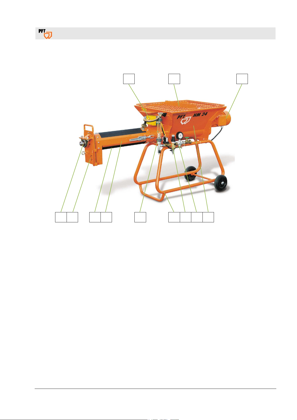
5 Overview HM 24
1 2 3
12 11 10 9 8 7 6 5 4
Fig. 1: Overview HM 24
1. ON / OFF switch
2. Protection grille
3. Mixer Motor
4. Material hopper
5. Water input, water connection
6. Water Manifold Unit
7. Frame
8. Water flow meter 100-1000 l/h
9. Mixing tube
10. Rubber mixing tube
11. Mortar outlet flange
12. Bearing
2017-08-07
9
PFT SCREW MIXER HM 24 Overview – Operation – Spare Parts Lists
Overview HM 24
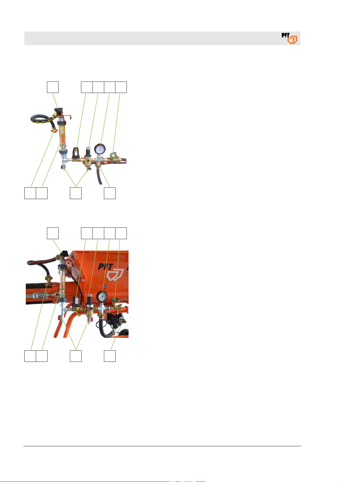
5.1 Water Manifold
1 2 3 4 5
1. Needle Valve.
2. Soleniod Valve.
3. Pressure Reducer.
4. Water Pressure Gauge.
5. Water Extraction Valve.
6. Water Mains.
7. Outlet Tap.
8. Water Flow Meter 100-1000 l/h.
9. Water to Mixing Tube.
9 8 7 6
Fig. 2: Water Manifold
5.2 Water Manifold with Water pressure booster pump
1 2 3 4 5
1. Needle Valve.
2. Soleniod Valve l.
3. Pressure reducer.
4. Water Pressure Gauge.
5. Water Extraction Valve.
6. Water Mains.
7. Outlet Tap.
8. Water Flow Meter 100-1000 l/h.
9. Water to Mixing Tube.
9 8 7 6
Fig. 3: Water Manifold with Water pressure
booster pump
10
2017-08-07

6 Type plate
The type plate contains the following information:
Fig. 4: Type plate
7 Quality control sticker
The quality control sticker contains the following information:
Fig. 5: Quality control sticker
8 Connections
PFT SCREW MIXER HM 24 Overview – Operation – Spare Parts Lists
Type plate
Manufacturer
Type
Year built
Machine number
CE confirmed in compliance with EU directives
Serial no. / serial number
Controlled by / signature
Date of control
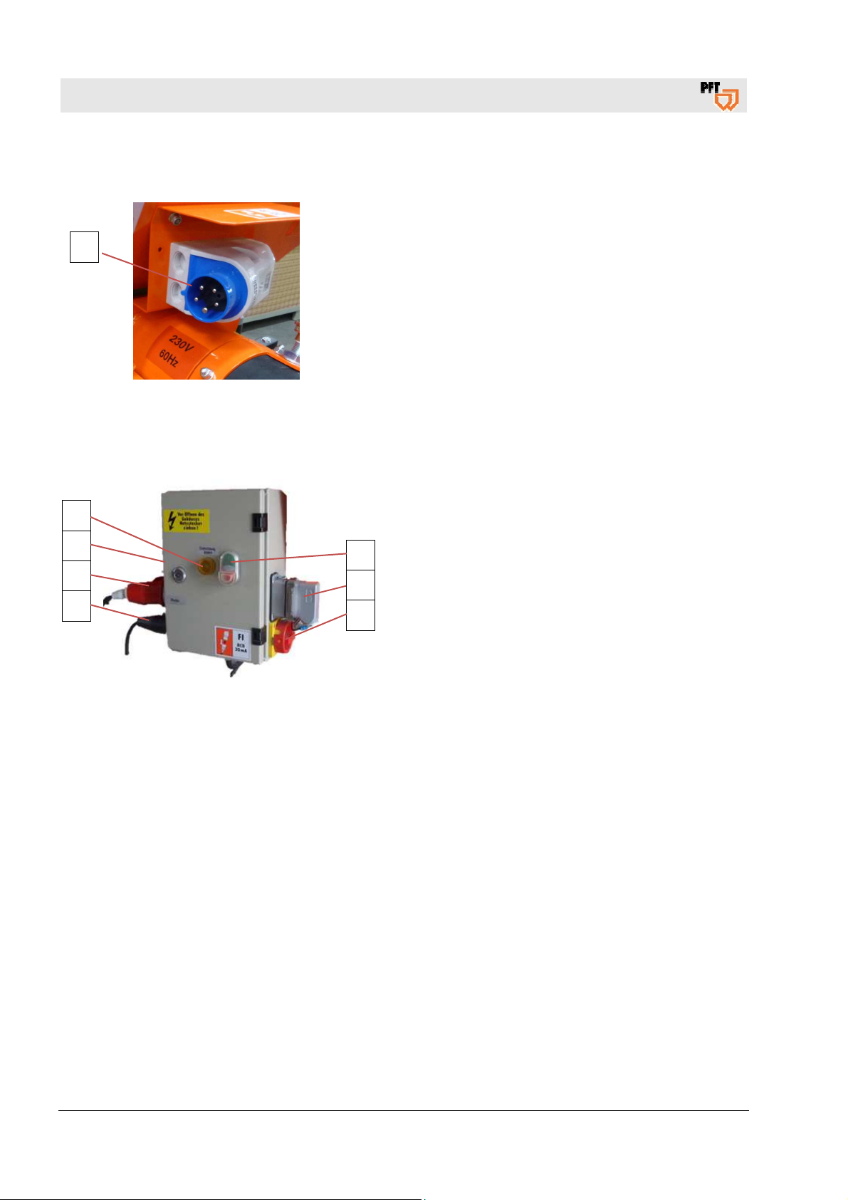
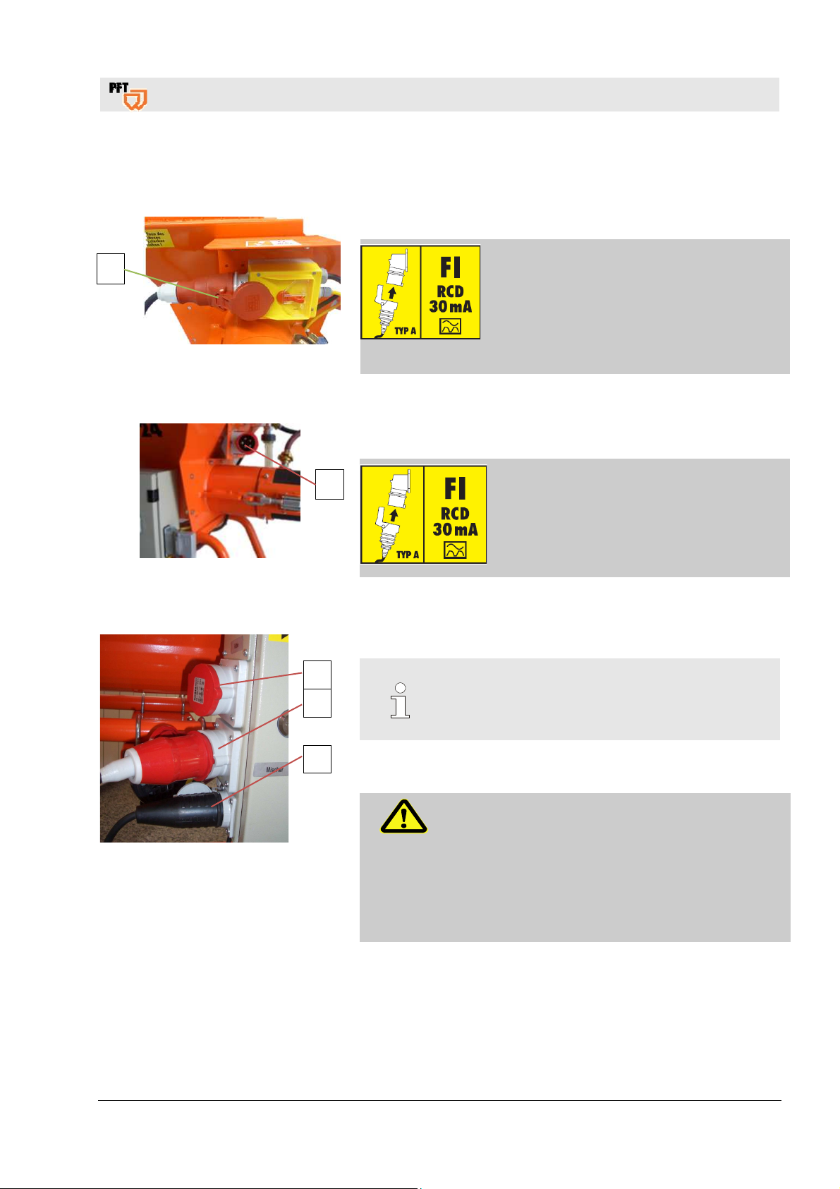
8.1 Connection without control box 400V
1
1. Three-phase current connection (1), 400 V.
Fig. 6: Electrical connection
8.2 Connection with control box 400V
1
Fig. 7: Electrical connection
1. Three-phase current connection (1), 400 V.
2017-08-07
11
PFT SCREW MIXER HM 24 Overview – Operation – Spare Parts Lists
Connections
8.3 Connection without control box 230V
1
2. Three-phase current connection (1), 230 V.
Fig. 8: Electrical connection
8.4 Connection HM 24 with control box
1. Operation press button ON - OFF.
7
6
5
4
Fig. 9: Connection control box
2. Blind plug / connector KPS1 probe.
3. Master switch is also emergency-stop switch.
1
4. Connection water pressure booster pump.
2
5. Connection geared motor.
3
6. Connection for vibrating unit.
7. Yellow pilot lamp, for wrong direction of rotation.
12
2017-08-07

blended dry
can be filled either by means of bags, a delivery hood or an
The machine consists of individual portable components whose handy
The PFT HM 24 is a new generation machine based on a modular concept. Use
The machine should only be operated in perfect working conditions. Comply with
all safety instructions in this manual! Rectify all defects and faults immediately.
ce with all operating instructions,
service from the
PFT SCREW MIXER HM 24 Overview – Operation – Spare Parts Lists
9 Description of Functions
PFT's HM 24 is a horizontal continuous screw mixer for factorymortars e.g.
masonry mortar
•
outdoor cement plasters (for rendering)
•
scratch coat
•
The PFT HM 24
injection hood.
dimensions and low weight allow for quick and easy transportation.
NOTE THE FOLLOWING CONNECTIONS WHILE OPERATING:
1. Electrical Panel - Main Switch
2. Water Mains - Water Manifold
3. Water Manifold - Mixing Tube
Description of Functions
the snaps to remove or fit on various dosing shafts and mixing tubes easily.
FOLLOW ALL MATERIAL MIXING INSTRUCTIONS FROM
MORTAR MANUFACTURER!
The following terms and symbols are used in this manual to highlight important
information:
NOTE:
Information for running the Machine efficiently.
WARNING!
Precautionary information for the prevention of accidents.
WARNING!
Proper machine operation includes full complian
carrying out specified inspections, and complying with maintenance instructions.
The most important safety instructions follow. Please read them thoroughly.
Comply with these instructions in order to get reliable quality
machine.
2017-08-07
13

PFT SCREW MIXER HM 24 Overview – Operation – Spare Parts Lists
Basic Saftey Instructions
10 Basic Saftey Instructions
1. Follow all safety instructions on the machine. Ensure that all instructions are legible
2. Inspect the machine once every shift for visible damages and defects. Stop operating
the machine immediately if you notice any changes in safety or operating behavior.
Notify a supervisor immediately.
3. Do not make any changes to the machine that can jeopardize its safety. Always
consult the machine dealer first. Do not tamper with the machine by equipping it with
extra "safety devices."
4. All spare parts must conform to our technical specifications. Only use spare parts
manufactured by PFT.
5. Only trained personnel should operate the machine. Clearly designate all lines of
responsibility for operation, equipping maintenance and repairs.
6. Technicians undergoing training in the operation of the machine should be
supervised by experienced personnel.
7. Only qualified personnel should work on the machine's electrical system. All
electrical work should only take place under the supervision of a qualified electrician
and should comply with electro-technical safety regulations.
8. Observe all instructions for switching the machine on and off. Watch display lamps
for signals.
9. When the machine is completely switched off for maintenance and repair work,
ensure that it cannot switch back on accidentaly. Do this by switching off the main
switch,
removing the key or by attaching a warning sign to the main switch.
10. Before cleaning the machine with a water jet, seal all openings that can be damaged
through water, e.g. electrical motors and control boxes, thoroughly. After cleaning
remove all seals and covers.
11. Use only original fuses with prescribed amps.
12. If work has to be carried out on a voltage-conducting component, a second technician
should stand by to switch off mains in case of an emergency.
13. Disconnect the machine from the mains before you move it, even if you are only
moving it a short distance. Reconnect the machine to the mains properly before
starting up again.
14. Set up the machine on stable ground. Secure it from rolling away or moving during
operation.
15. Depressure all conveying systems before dismantling them.
16. Have the machine inspected at once a year by a qualified person. The machine
should also be inspected otherwise as required.
14
2017-08-07

PFT SCREW MIXER HM 24 Overview – Operation – Spare Parts Lists
11 Safety rules
Caution!
Please observe the regional safety rules for mortar
pumping while performing all jobs!
12 Transport, packing and storage
12.1 Safety instructions for transport
Improper transport
Suspended loads
ATTENTION!
Damage from improper transport!
Improper transport may cause substantial property
damage.
When unloading the packages on delivery as
Use only the specified anchorage points.
Remove packaging only shortly before the
WARNING!
Danger to life from suspended loads!
When lifting heavy loads there is danger to life from
falling parts or uncontrolled swinging parts.
Therefore:
Never step under suspended loads.
Observe the instructions regarding the
Do not fix to projecting machine parts or
Ensure safe fit of the sling gear.
Use only approved lifting gear and sling gear
Safety rules
well as transport within the company pay
attention and observe the symbols and
instruction on the package.
assembly.
provided anchorage points.
eyelets of attached components.
with sufficient lifting capacity.
2017-08-07
15

PFT SCREW MIXER HM 24 Overview – Operation – Spare Parts Lists
Packaging
12.2 Transport inspection
Immediately after receipt, check to ensure that the delivery is
complete and free of transport damages.
Proceed as follows if there are externally identifiable transportation
damages:
Do not accept delivery or accept delivery only under
reservation.
Mention the scope of damage on the transport documents or on
the delivery receipt of the transport agency.
NOTE:
Complain about each defect as soon as it is
detected. Damage claims can be filed only within
the valid complaint periods.
Transportation of machine already
in operation
DANGER!
Danger of injury through mortar discharge!
Face and eyes can be damaged.
Perform the following steps before transportation:
1. Pull out the main power cable first.
2. Detach all other cable connections.
3. Remove water supply line.
4. Start transportation.
13 Packaging
On packaging The individual units are packaged in accordance with the expected
transport conditions. Environment-friendly materials were used for
packaging.
The packaging should protect the individual components from
transport damages, corrosion and other damages up to installation.
Hence, do not destroy the packaging and remove it only just before
installation.
16
2017-08-07

PFT SCREW MIXER HM 24 Overview – Operation – Spare Parts Lists
Operation
Handling packaging materials If no return agreement was signed for the packaging, separate the
materials according to type and size and channelize them for
further use or reuse.
CAUTION!
Environment damages due to incorrect
disposal!
Packaging materials are valuable raw materials
and can be used further or processed meaningfully
and reused in many cases.
Hence:
– Dispose of packaging material in an
environment-friendly manner.
– Observe the locally applicable disposal
specifications. If necessary, commission a
specialized company to perform the disposal.
14 Operation
14.1 Safety
Personal protection equipment
The following protective equipment must be worn while performing
all jobs:
Work safety clothing
Safety glasses
Safety gloves
Safety shoes
Hearing protection
NOTE:
Further protective equipment that is to be worn
when effective particular jobs will be pointed out
separately in the warning instructions of this
chapter.
2017-08-07
17
PFT SCREW MIXER HM 24 Overview – Operation – Spare Parts Lists
Preparing the machine
Basic information
WARNING!
Danger of injury due to incorrect operation!
Improper operation may lead to serious damage to
persons or property.
Therefore:
Carry out all operating steps according to the
instructions in this user manual.
Prior to starting your work, ensure that all covers
and protection devices are installed and work as
intended.
Never deactivate protection devices during
operation.
Ensure order and cleanliness in the work area!
Loose components and tools on top of one
another or lying about pose potential accident
risks.
Increased noise level may cause permanent
hearing deficiencies. At close range of the
machine 78 dB(A) can be exceeded due to
operational conditions. Close range is a distance
of less than 5 metres to the machine.
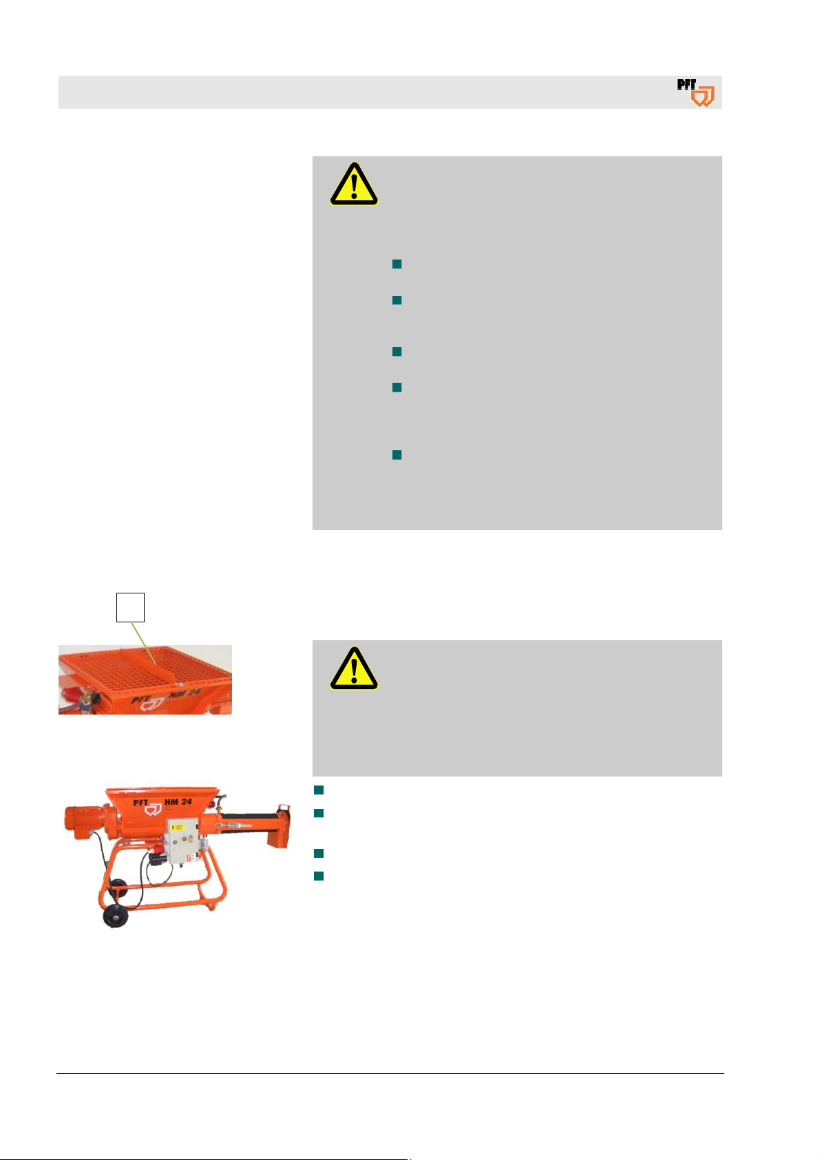
15 Preparing the machine
1
Fig. 10: Grille cover
Fig. 11: Set-up
Prior to operating the machine carry out the following steps for
preparing the machine:
DANGER!
Rotating dosing shaft!
Risk of injury when reaching into the material
container.
– During machine preparation and operation, the
grille cover (1) must not be removed.
– Never reach into the running machine.
The operating elements have to be freely accessible.
Put up the machine on a stable, even surface and secure
against unwanted movements:
Neither tilt nor roll off the machine.
Put up the machine in such a way that it cannot be hit by falling
objects.
18
2017-08-07
PFT SCREW MIXER HM 24 Overview – Operation – Spare Parts Lists
16 Connecting the power supply
16.1 Power connection without control cabinet
1. Connect machine (1) to three-phase network 400V.
Connecting the power supply
1
Fig. 12: Power supply 400 V
16.2 Power connection with control cabinet
1. Connect machine (1) to three-phase network 400V.
1
Fig. 13: Power supply 400 V
16.3 Check the individual connectors
Connect water pump (1).
DANGER!
Danger of death from electric current!
The connection line has to be fused
properly:
Connect the machine only to a power source
with permissible RCCB (30 mA) RCD
(residual current operated device) type A.
DANGER!
Danger of death from electric current!
The connection line has to be fused properly:
Connect the machine only to a power source
with permissible RCCB (30 mA) RCD
(residual current operated device) type A.
Fig. 14: Power connections
3
2
1
Check connection of mixing motor (2).
NOTE!
The booster pump is necessary should the water
pressure be less than 2.5 bar when the machine is
running.
Check connection of Vibrator (3).
WARNING!
Danger to life from rotating parts!
Improper operation may lead to serious damage to
persons or property.
The respective drive (motors) must be operated
only with the control cabinet of the machine.
Using other or external power sources is forbidden
for safety reasons.
2017-08-07
19

PFT SCREW MIXER HM 24 Overview – Operation – Spare Parts Lists
Check the direction of rotation
17 Check the direction of rotation
17.1 Main switch on the control cabinet
Switch on the main selector switch (1).
2
1
Fig. 15: M
ain switch
17.2 On/Off switch with phase inverter
Fig. 16: On/Off switch with phase inverter
Rotating field control:
All three phases are present and the rotating field is OK: LED
green lights up.
1
One phase is missing: LED flashes red.
L1 is missing: LED red flashes 1x (fast).
L2 is missing: LED red flashes 2x (fast).
L3 missing: LED red flashes 3x (fast).
Wrong rotating field: LED red is always lit.
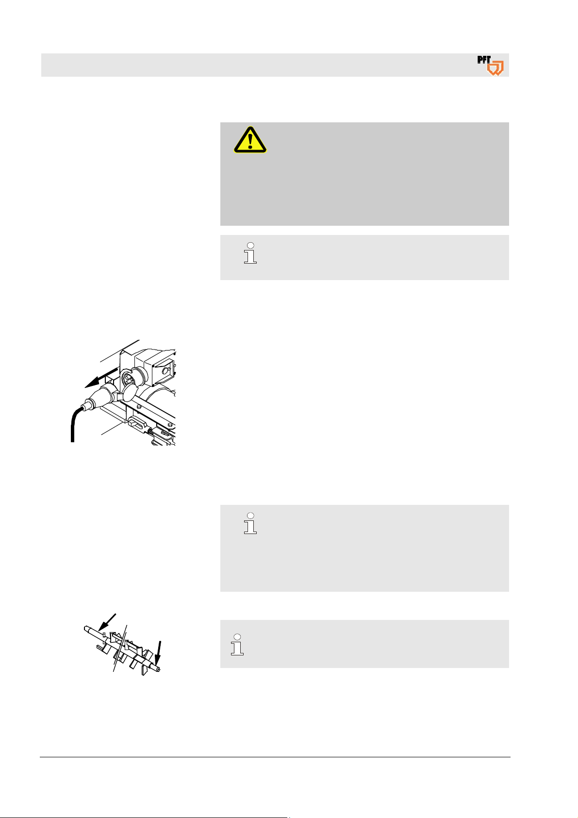
The PFT HM 24 is equipped with a phase display that will light up if
the direction of rotation is wrong. With the right phase order, the
mixing shaft should rotate clockwise.
The PFT HM 24 is equipped with a contact reversing switch that
enables the user to change the direction of rotation.
To do this, disconnect the power cable and alter the contacts with
a screw driver (1).
HINWEIS!
Check the direction of rotation.
If the direction of rotation is incorrect, the yellow
direction indicator (2) lights up and the following
steps must be carried out:
The main selector switch (1) is locked in the neutral
position by sliding the selector plate to the left or
right in a preset position, thus selecting the direction
of rotation. If the switch is on the left, the switch can
be switched back to zero, but is disabled for the right
position.
20
2017-08-07

PFT SCREW MIXER HM 24 Overview – Operation – Spare Parts Lists
17.3 Connecting the power supply 230 V
1. Connect machine (1) only to a 230V AC network.
1
Fig. 17: Power connection
2. Interrupt the control circuit by removing the plugs (2) from the
control cabinet.
3. Remove connector Air compressor (3) from control cabinet.
Setting Up the Machine
DANGER!
Danger of death from electric current!
The connection line has to be fused
properly:
Connect the machine only to a power
source with permissible 30 mA FI
protection switch RCD (residual current
operated device) of type “B” that is
sensitive to all currents that are required
for the operation of frequency
converters.
18 Setting Up the Machine
Assemble the machine as follows:
Set up the hopper straight
•
Insert the mixing shaft into the dosing shaft.
•
Mount mixing tube and secure it on the hopper with snaps.
•
Attach protection grill.
•
Water Supply
Connect a 3/4“ hose to water mains. Open water discharge
•
valve slightly. Let water run through the hose to deaerate and
clean it. Wait till water comes out of the hose.
Shut off water discharge valve.
•
Connect water hose to water inlet on the machine (dirt filter).
•
Open the water mains. If water pressure is under 2,5 bar, attach
•
water boosterpump AV 3 ( Item no. 00 00 11 40 ) to the mains.
WARNING!
Danger to life from rotating parts!
Improper operation may lead to serious damage to
persons or property.
The respective drive (motors) must be operated
only with the control cabinet of the machine.
2017-08-07
21

PFT SCREW MIXER HM 24 Overview – Operation – Spare Parts Lists
Setting Up the Machine
Caution!
While using stored water from a tank, connect the
suction inlet with a filter.
(Item no. 20 47 50 00) ( deaerate water pump )
Connect the water hose of the needle valve to the mixing tube.
When the PFT HM 24 has been completely assembled and
connected, follow these steps:
Fill hopper.
•
Switch on the HM 24 at main switch.
•
Regulate the amount of water at the needle valve.
Mortar Consistency
Adjust the needle valve in such a way that the machine emits
trowel-suited mortar at the mortar outlet.
NOTE:
Follow all material mixing instructions of the mortar
manufacturer!
NOTE:
Interrupting Work!
The length of a break during operation will depend on
the material and on the
conditions at the construction site (e.g. temperature,
humidity etc.)
22
NOTE:
Follow all material mixing instructions of the mortar
manufacturer!
2017-08-07

18.1 Water from a water barrel
Booster pump AV3000/1 (1) item number 00493686
1
The booster pump which is connected ensures the required water
pressure of minimum 2.5 bar.
PFT SCREW MIXER HM 24 Overview – Operation – Spare Parts Lists
Putting the machine into operation
NOTE!
When working with water from the barrel,
the inlet strainer must be fitted with a filter strainer
(item no. 00136619) (bleed booster pump).
19 Putting the machine into operation
19.1 Hazardous dust
WARNING!
Danger of health problems due to dust!
Inhaled dust can lead to long-term lung damage
or other health problems.
NOTE!
The machine operator or the person working in the
dusty area must always wear a dust mask when
filling the machine.
The decisions of the Committee for Hazardous
Materials (AGS) can be read in the Technical Rules
for Hazardous Substances (TRGS 559).
2017-08-07
23
While assembling cleaned parts, make sure they are
PFT SCREW MIXER HM 24 Overview – Operation – Spare Parts Lists
Cleaning
20 Cleaning
Locking to prevent reactivation
Connect 1/2" water hose with Geka coupling (Item no. 20 21 11 00)
DANGER!
Danger to life from unauthorized reactivation!
While working at the machine one is exposed to
the danger that the power supply may be activated
without authorization. This exposes the persons in
the danger zone to the risk of death.
– Before starting work, switch off all power
supplies and lock them against reactivation.
NOTE:
The machine must be cleaned daily after work and
after long pauses.
and spray nozzle (Item no. 20 21 57 00) to water mains.
Cleaning should take place in the following 5 steps:
When the hopper is 1/3 full, reduce the water entry at the needle
•
valve by a quarter. Switch off the PFT HM 24 as soon as highly
diluted mortar is discharged.
Remove the coupling of the power cable before disconnecting
•
the mixing tube, or else the safety hook on the machine will block
the coupling.
Open the snaps on the mixing tube and remove it. Release the
•
mixing shaft and clean it along with the mixing tube. Use a trowel
and water for this purpose.
Clean the hopper on the outside with a brush or dry mop. Use
•
water to clean the hopper only when it is empty.
NOTE:
No water should enter the bearings or electrical
parts ( plug, main switch, motor connections box).
24
really dry and clean. Connect mixing shaft to dosing
shaft.
NOTE:
Keep all snaps and seals clean.
Grease bearing tang and connectors regularly.
2017-08-07

PFT SCREW MIXER HM 24 Overview – Operation – Spare Parts Lists
21 Measures against danger of frost
1. Remove hose (1) from water connecting piece on the mixing
zone.
1
2. Remove water hose (2) from water inlet.
3. Open the two release cocks (3) on the fittings block.
4. Drain out water and shut the cocks again.
3
3
2
CAUTION!
Damage due to frost!
Water that expands inside the machine during
frosting can damage it seriously.
– Perform the following steps if the machine is out
of operation due to the danger of frost.
Measures against danger of frost
22 Measures during power failure
The PFT HM 24 is equipped with a restart lock. After a power
failures switch on the machine at the main switch for operation.
23 Measures for Water Supply Failure
In case of a water supply failure, the PFT HM 24 will keep on
running without mixing the material. As soon as the fault is
rectified, the HM 24 will mix material quite
normally again.
24 Maintenance
24.1 Safety
Personal
Some maintenance jobs may be performed only by specially
trained mechanics or exclusively by the manufacturer.
Jobs on the electrical system may in principle be performed
only by electricians.
2017-08-07
25

PFT SCREW MIXER HM 24 Overview – Operation – Spare Parts Lists
Maintenance
Basic
Electrical system
WARNING!
Danger of injury from improperly performed
maintenance jobs!
Improper maintenance can lead to serious personal
injuries and material damages.
Hence:
– Ensure sufficient installation space before
starting work.
– Pay attention to cleanliness and order at the
installation site! Components and tools lying
loosely on each other or lying scattered are
accident sources.
– Ensure correct installation if components are
removed, reinstall all fastening elements and
screw torques.
DANGER!
Danger to life from electric current!
Contact with electrically live components poses
danger to life. Activated electrical components can
execute uncontrolled movements and lead to
serious injuries.
Hence:
– Before starting work, switch off the power
supply and lock the switch against reactivation.
Environment protection
24.2 Cleaning
The material container can be cleaned internally with a water hose after being emptied fully.
Observe the following instructions on environment protection while
performing maintenance jobs:
Remove discharged, used up or excess grease from all
lubrication points that are lubricated manually, and dispose it in
accordance with the valid local provisions.
Collect the replaced oil in suitable containers and dispose
according to the valid local provisions.
CAUTION!
Water can penetrate into sensitive machine
components!
– Before cleaning the machine, cover all openings
into which water should not enter for safety and
functional reasons (for example: electric motors
and control cabinets).
– Remove the covers fully after the cleaning.
26
2017-08-07

24.3 Maintenance schedule
24.4 Dirt trapping sieve
PFT SCREW MIXER HM 24 Overview – Operation – Spare Parts Lists
Maintenance
If increased wear and tear is detected during the regular checks,
shorten the required maintenance intervals according to the actual
wear and tear.
After every operation, check the following parts for defects:
bearings, hauling bracket, all connectors, hose connections and
power cable connections.
Check dirt trapping sieve in the water inlet daily:
1. Take out dirt trapping sieve from the Geka coupling.
2. Clean dirt trapping sieve.
3. Replace sieve if there are thick dirt deposits.
4. Reinsert dirt trapping sieve
Dirt trapping sieve Geka coupling: Article No. 20152000
.
Remove and clean the dirt filter in the water inlet and in the
pressure reducer at least once every two weeks. Replace them, if
necessary. Open filter holder with special spanner ( Item
no. 20 10 24 00 ).
2017-08-07
27

PFT SCREW MIXER HM 24 Overview – Operation – Spare Parts Lists
Dismantling
25 Dismantling
On reaching the end of its life span, the device must be dismantled
25.1 Safety
Personal The device is to be dismantled only by specially trained
Basics
Electrical system
and disposed in an environment-friendly manner.
technicians.
Jobs on the electrical system may be performed only by
electricians.
WARNING!
Risk of injury from improper dismantling!
Stored residual energies, sharp-edged
components, tips and corners on or in the device or
on the required tools can cause injuries.
Hence:
– Ensure sufficient free space before starting
work.
– Handle open sharp-edged components
carefully.
– Pay attention to cleanliness and order at the
workplace! Components and tools lying loosely
on each other or lying scattered are accident
sources.
– Dismantle components properly. Consider the
partially high dead weight of the components.
Use lifting tools if necessary.
– Lock components so that they do not fall down
or topple over.
– Contact the manufacturer in case of doubt.
DANGER!
Danger to life from electric current!
Contact with electrically live components poses
danger to life. Activated electrical components can
execute uncontrolled movements and lead to
serious injuries.
Hence:
– Switch off and cut the power supply
permanently before starting the dismantling
operation.
28
2017-08-07

25.2 Dismantling
25.3 Disposal
PFT SCREW MIXER HM 24 Overview – Operation – Spare Parts Lists
Dismantling
For selection, clean the device and take it apart according to the
valid work safety and environment protection specifications.
Before start of dismantling:
Switch off device and lock it against reactivation.
Cut total power supply from device physically, discharge stored
residual energies.
Remove operating and auxiliary substances as well as
remaining processing materials and dispose of them in an
environment-friendly manner.
Recycle the dismantled components if no return- or disposal
agreement was signed:
Scrap metals.
Recycle plastic elements.
Dispose of the remaining components sorted by material
quality.
CAUTION!
Environmental damages due to incorrect
disposal!
Electrical scrap, electronic components, lubricants
and other auxiliary substances are subject to
special waste treatment, and may be disposed only
by certified specialized companies!
The local municipal authorities or specialized disposal companies
provide information about environment-friendly disposal.
2017-08-07
29

PFT SCREW MIXER HM 24 Overview – Operation – Spare Parts Lists
Spare parts drawing
26 Spare parts drawing
26.1 Hopper with Frame Unit
26
25
24
23
22
21
20
19
18
17
16
1
2
3
4
5
6
7
8
9
10
11
12
13
10
14
15
30
2017-08-07

PFT SCREW MIXER HM 24 Overview – Operation – Spare Parts Lists
Spare parts drawing
26.2 Spare parts list Hopper with Frame Unit
Item Qty. Art.No. Description
1 1 00 00 21 13 Protection grill with rounded frame
2
3 1 00 00 25 69 Dosing shaft HM 22/24 35l at 280rpm
4 1 00 00 21 12 Material hopper HM 22/24 RAL2004
1 00 02 05 81 Material hopper HM 22/24 removable motor flange 2004
5 4 20 20 72 00 Safety nut M 8 galv.
6 1 20 54 57 02 Sealing ring for drive D 107x40x5
7 1 00 25 15 80 Seal ring for gear sealing D160x110x4
8 1 20 54 57 05 Clamping flange for rubber seal HM
9 4 20 20 78 01 Hex. screw M8 x 35 galv.
10 4 20 20 86 04 Quick fastener with cap 16s x N 2 7 (packing unit = 10 pcs)
1 00 21 45 19 Securing disk and saucer head screw M8x25 cpl.
11 2 20 70 58 02 Bolt A16 H11 x 50
12 2 20 20 99 21 Collar nut M16
13 2 20 20 85 00 Eye screw M16 x 80, galvanised
14 2 20 54 83 10 Wheel 180 x 50 x 90
15 2 20 20 86 03 Fastener with cap 20s x N 2 7
16 1 00 00 78 76 Frame HM 22/24 (1") RAL2004
17 1 20 20 72 00 Safety nut M 8 galv.
18 4 20 20 93 13 Washer B 8,4 galv.
19 4 20 20 87 01 Hex. screw M8 x 16 galv.
20 4 20 20 96 11 Screw with inner thread. M4 x 12 galv.
21 1 20 54 95 15 Clamping flange for mixing tube seal HM 2/200/2002
22 1 20 54 80 10 Rubber seal D154 X D107 X 5
23 1 20 54 71 03 Dosing wear-tube HM 200/2002 D102 x 151
24 2 20 20 72 00 Safety nut M 8 galv.
25 2 20 20 78 10 Hex. screw M8 x 25 galv.
26 1 00 04 07 21 Dosing shaft HM 104 35l at 280 rpm
For spare parts orders only with specification of the type plate!
2017-08-07
31

PFT SCREW MIXER HM 24 Overview – Operation – Spare Parts Lists
Spare parts drawing
26.3 Drive Unit Art.No. 00211876
32
2017-08-07

PFT SCREW MIXER HM 24 Overview – Operation – Spare Parts Lists
Spare parts drawing
26.4 Spare parts list Drive Unit Art.No. 00211876
Item Qty. Art.No. Description
1 1 00 42 92 99 Geared motor ZF21 3kw 274rpm RAL2004
2 1 00 01 01 61 Protection bail for motor adjustable for HM 202/204 RAL2004
3 1 20 42 41 10 Motor connection cable 0,85m CEE plug 4x 16A 6h red loop 4mm
4 1 20 42 79 00 Plug CEE 4 x 16A 6h red
5 4 20 20 72 00 Safety nut M 8 galv.
6 4 20 20 78 10 Hex. screw M8 x 25 galv.
7 1 00 01 01 60 Motor flange without protection bail HM 202/204 RAL2004
8 1 20 54 80 20 Gasket 200 x 190 x 10 D160
9 1 20 10 29 11 Hauling bracket with round funnel 25 mm boring HM 2/HM 200
10 1 20 20 96 03 Threaded pin hex. M8 x 20 galv.
For spare parts orders only with specification of the type plate!
2017-08-07
33

PFT SCREW MIXER HM 24 Overview – Operation – Spare Parts Lists
Spare parts drawing
26.5 Drive Unit 60Hz Art.No. 00265323
1 2 3
8
7 6 5 4
34
2017-08-07

PFT SCREW MIXER HM 24 Overview – Operation – Spare Parts Lists
Spare parts drawing
26.6 Spare parts list Drive Unit Art.No. 00265323
Item Qty. Art.No. Description
1 1 20 42 79 01 Plug CEE 4 x 16A 9h blue
1 00 06 62 83 Motor connection cable CEE 4 x 16A - 1.2 m cpl.
2 1 00 42 92 99 Geared motor ZF21 3kw 274rpm RAL2004
3 1 00 01 01 61 Protection bail for motor adjustable for HM 202/204 RAL2004
4 1 00 02 20 86 CEE-Panel mounted socket 4 x 16A 9h blue
5 1 20 54 80 20 Gasket 200 x 190 x 10 D160
6 1 20 10 29 11 Hauling bracket with round funnel 25 mm boring HM 2/HM 200
7 1 20 20 96 03 Threaded pin hex. M8 x 20 galv.
8 1 00 01 01 60 Motor flange without protection bail HM 24 RAL2004
For spare parts orders only with specification of the type plate!
2017-08-07
35

PFT SCREW MIXER HM 24 Overview – Operation – Spare Parts Lists
Spare parts drawing
26.7 Drive Unit
8
7
6
5
4
1
2
3
36
2017-08-07

PFT SCREW MIXER HM 24 Overview – Operation – Spare Parts Lists
Spare parts drawing
26.8 Spare parts list Drive Unit
Item Qty. Art.No. Description
1
2
3
4
5
6
7
8
For spare parts orders only with specification of the type plate!
1 00 42 92 99 Geared motor ZF21 3kw 274rpm RAL2004
1 20 42 41 10 Motor connection cable 0,85m CEE plug 4x 16A 6h red loop 4mm
1 20 42 79 00 Plug CEE 4 x 16A 6h red
1 00 00 21 10 Cover with flap HM 22/24
1 20 20 91 10 Spring washer B 12 galv.
1 00 00 81 49
Hex. screw M12 X 60 modified stainless
1 20 20 96 03 Threaded pin hex. socket. M8 x 20 galv.
1 00 13 98 10 Hauling bracket Hm 22 / 24 galv. cpl.
2017-08-07
37

PFT SCREW MIXER HM 24 Overview – Operation – Spare Parts Lists
Spare parts drawing
26.9 Mixing Tube Unit Art.No. 00012594
1 2 3 4 5 6 7 8 9 10 11 12 13
33
32
31
30
29
28
27
26
25 24 23 22 21 20 19 18 17 16 15 14
38
2017-08-07

PFT SCREW MIXER HM 24 Overview – Operation – Spare Parts Lists
Spare parts drawing
26.10 Spare parts list Mixing Tube Unit Art.No. 00012594
Item Qty. Art.No. Description
1 1 00 01 25 94
2 2 20 20 87 01 Hex. screw M8 x 16 galv.
3 10 20 20 66 03 Safety nut M8 galv.
4 1 20 20 63 23 Saucer-head screw M8 x 25 galv.
5 1 00 01 25 93 Rubber mixing tube HM 104/204 620mm long coped
6 4 20 20 63 23 Saucer-head screw M8 x 25 galv.
7 2 20 20 85 22 Pin 8 H11 x 58 x 54 with washer and spline galv.
8 2 20 10 08 01 Snap lock with safety device M14
9 1 00 01 25 91 Flange for rubber mixing tube HM 2 with fixed mortar output
10 1 00 00 22 29 Water inlet for ruber mixing tube HM 2
11 1 20 20 93 15 Washer
12 1 00 00 28 11 Nut 1/2" int. thread
13 1 20 20 13 00 Geka coupling 1/2" int. thread
14
1 00 43 11 98 Sprocket mixing shaft HM 104 4 rows RAL2004 (Art.Nr. 00070219)
15 1 00 00 25 69 Dosing shaft HM 22/24 35l at 280rpm
16 1 00 02 14 95 Mixing shaft HM 2002 (3 levels)
17 1 20 54 76 00 Dowel pin 10 x 40
18 1 20 54 76 03 Dowel pin 6 x 40
19 1 00 01 25 92 Mortar output flange fixed to rubber mixing tube HM 2 RAL2004
20 1 00 01 94 21 Rubber front plate for mortar output flange
21 1 20 20 78 00 Hex. screw M8 x 30 galv.
22 1 20 20 79 50 Ring nut M8 galv.
23 1 00 01 94 20 Front plate for mortar output flange RAL2004
24 1 20 54 55 01 Bearing with square bore and housing
25 2 20 20 99 63 Hex. screw M12 x 25 galv.
26 1 00 02 04 09 Cylindrical screw M8 x 25
27 1 20 20 93 14 Washer A 8,4 galv.
28 1 20 54 54 09 Locking disc for HM galv.
29 1 20 54 55 06 Bearing with square bore
30 1 00 04 13 96 Housing for bearing Y-P 80
31 2 20 20 89 00 Safety nut M12 galv.
32 1 20 20 97 11 Hex. socket head screw M8 x 20 galv.
33 1 20 20 64 00 Hex. nut M8 galv.
Mixing tube HM 2 with rubber mixing zone and fixed mortar output flange
RAL2004
For spare parts orders only with specification of the type plate!
2017-08-07
39

PFT SCREW MIXER HM 24 Overview – Operation – Spare Parts Lists
Spare parts drawing
26.11 Mixing Tube Unit HM22/24 Art.No. 00002116
1 2 3 4 5 6 7
18
17
16
15
14
13
8
9
10
11
12
40
2017-08-07

PFT SCREW MIXER HM 24 Overview – Operation – Spare Parts Lists
26.12 Spare parts list Mixing Tube Unit Art.No. 00002116
Item Qty. Art.No. Description
Spare parts drawing
1
2
3
4
5
6
7
1 00 00 21 16 Mixing tube HM 22/24 cpl.
1 00 00 21 17 Mixing tube HM 22/24
2 20 20 09 00 Geka coupling 1/2" ext. thread (packing unit = 10 pcs)
3 20 20 17 00 Gasket Geka-coupling (packing unit = 50 pieces)
1 20 20 16 50 Geka coupling dummy cover
2 20 10 08 01 Snap lock with safety device M14
2 20 20 85 22 Pin 8 H11 x 58 x 54 with washer and spline galv.
8 2 20 20 99 92 Threaded pin hex.socket M6 x 6 galv.
9
10
11
12
13
14
15
16
17
18
1 20 02 60 01 Glide bearing with insert
1 20 02 60 02 Bearing bushing Thermoplast D60 x 40
1 20 54 82 10 Bearing bush HM 2/2000/2002 with bushing
1 00 01 99 67 Mixing shaft HM 2/22/24/2002 with scraper
1 20 54 76 00 Dowel pin 10 x 40
1 20 54 76 03 Dowel pin 6 x 40
2 20 20 72 00 Safety nut M 8 galv.
2 20 20 93 13 Washer B 8,4 galv.
2 00 00 86 14 Security-screw, buttonhead with socket and flat M8 x 16 A2
1 00 00 71 52 Safety hook for CEE plug RAL2004
For spare parts orders only with specification of the type plate!
2017-08-07
41

PFT SCREW MIXER HM 24 Overview – Operation – Spare Parts Lists
Spare parts drawing
26.13 Mixing Tube Unit Art.No. 20548520
1 2 3 4 5 6
15
14
13
12
11
10
7
8
9
42
2017-08-07

PFT SCREW MIXER HM 24 Overview – Operation – Spare Parts Lists
26.14 Spare parts list Mixing Tube Unit Art.No. 20548520
Item Qty. Art.No. Description
Spare parts drawing
1
2
3
4
5
6
7
8
9
10
11
12
13
14
15
1 20 54 85 20 Mixing tube HM 2/200/2002 cpl.
2 20 20 85 22 Pin 8 H11 x 58 x 54 with washer and spline galv.
2 20 10 08 01 Snap lock with safety device M14
2 20 20 09 00 Geka coupling 1/2" ext. thread (packing unit = 10 pcs)
1 20 20 17 00 Gasket Geka-coupling (packing unit = 50 pieces)
1 20 20 16 50 Geka coupling dummy cover
1 20 54 81 05 Mixing tube HM 2/200/2002 RAL2004
1 20 55 29 10 Safety chain 2mm 250mm long K20
1 20 10 10 10 Splint D 4,5 with ring
1 20 54 55 01 Bearing with square bore and housing
2 20 20 68 01 Hex. screw M12 x 30 galv.
1 20 54 55 06 Bearing with square bore
1 00 04 13 96 Housing for bearing Y-P 80
2 20 20 89 00 Safety nut M12 galv.
1 20 54 81 03 Mortar outlet flange removable HM 2/200/2002 RAL2004
For spare parts orders only with specification of the type plate!
2017-08-07
43
PFT SCREW MIXER HM 24 Overview – Operation – Spare Parts Lists
Spare parts drawing
26.15 Electrical Unit 400V 60Hz
1 2 3 4 5 6
7
8
9
10
26.16 Spare parts list Electrical Unit 400V 60Hz
Item Qty. Art.No. Description
1 1 00 00 71 53 Support for mounted plug HM 22/24/2002
2 2 20 20 61 00 Hex. screw M8 x 20 galv.
3 2 20 20 93 13 U disc B 8,4 galv.
4 2 20 20 72 00 Nut M8 galv.
5 2 20 20 62 03 Nut M4 galv.
6 2 20 20 63 05 Cylindrical screw M4 x 12 galv.
7 1 00 21 24 19 Cable set HM24 400V 60Hz
8 1 00 45 64 61 Plug solenoid valve 400V 50/60Hz
9 1 00 04 11 41 Skintop screwed joint M16 x 1,5
10 2 00 04 11 42 Skintop screwed joint M25 x 1,5
11 1 00 21 18 78 On/Off switch with phase changing device 6.5-10A 60Hz
12 1 00 02 20 73 CEE-Socket 4 x 16A 6h red
11
12
44
2017-08-07
PFT SCREW MIXER HM 24 Overview – Operation – Spare Parts Lists
Spare parts drawing
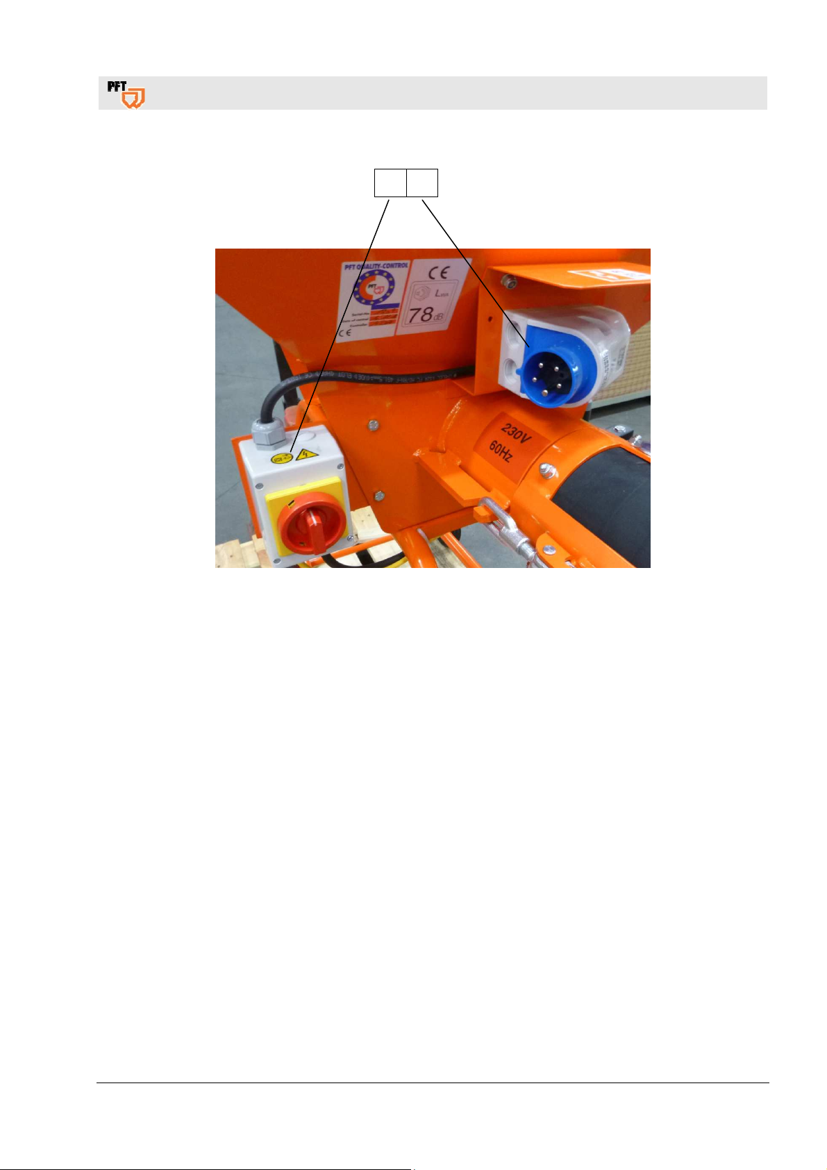
26.17 Electrical Unit 230V 60Hz
1 2
Item Qty. Art.No. Description
1 1 20 45 69 46 On/Off switch with motor protection 10-16 A, 230 V, 60 Hz
2 1 00 02 20 80 CEE connection plug, phase inverter 5 x 16A 9h, blue
For spare parts orders only with specification of the type plate!
2017-08-07
45
PFT SCREW MIXER HM 24 Overview – Operation – Spare Parts Lists
Spare parts drawing
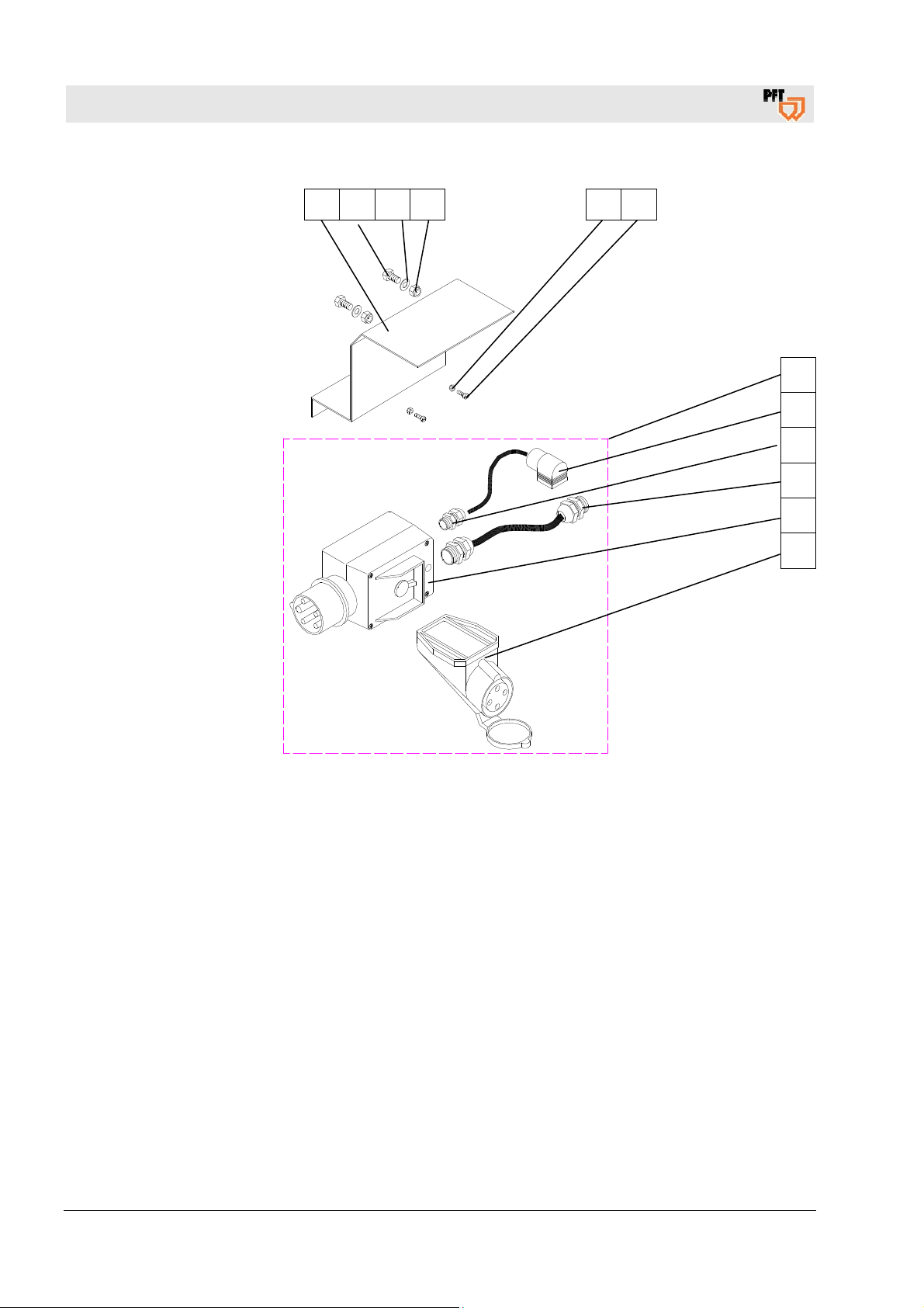
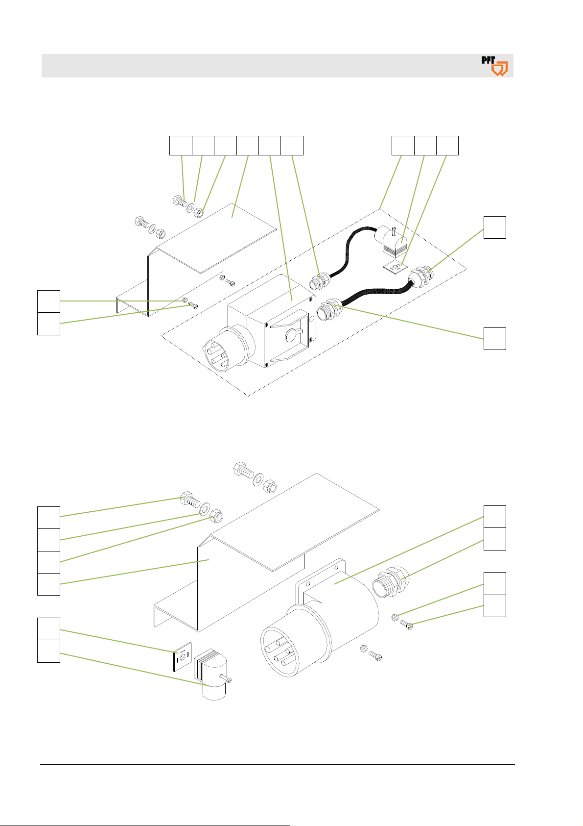
26.18 Cable set HM 24 Art.No. 00002127
1 2 3 4 5 6 7 8 9
12
13
26.19 Support for mounted plug HM 22/24/2002
10
10
1
2
3
4
9
8
11
10
12
13
46
2017-08-07

Item Qty. Art.No. Description
PFT SCREW MIXER HM 24 Overview – Operation – Spare Parts Lists
Spare parts drawing
1
2
3
4
5
6
7
8
9
10
11
12
13
4 20 20 61 00 Hex. screw M8 x 20 galv.
4 20 20 93 13 Washer B 8,4 125 galv.
4 20 20 72 00 Safety nut M 8 985 galv.
2 00 00 71 53 Support for mounted plug HM 22/24/2002
1 00 00 12 28 On/Off switch with phase changing device 6.5-10A
1 00 04 11 41 Connector skintop with nut M16 x 1.5
1 00 00 21 27 Cable set HM 24
2 00 02 20 63 Plug solenoid valve
2 20 15 26 12 Gasket solenoid coil type 280
3 00 04 11 42 Skintop screwing M 25 x 1.5
1 00 02 20 75 CEE-plug 5 x 16A 6h
4 20 20 62 03 Safety nut M4 galv.
4 20 20 63 05 Cheese-head screw M4 x 12
For spare parts orders only with specification of the type plate!
2017-08-07
47
PFT SCREW MIXER HM 24 Overview – Operation – Spare Parts Lists
Spare parts drawing
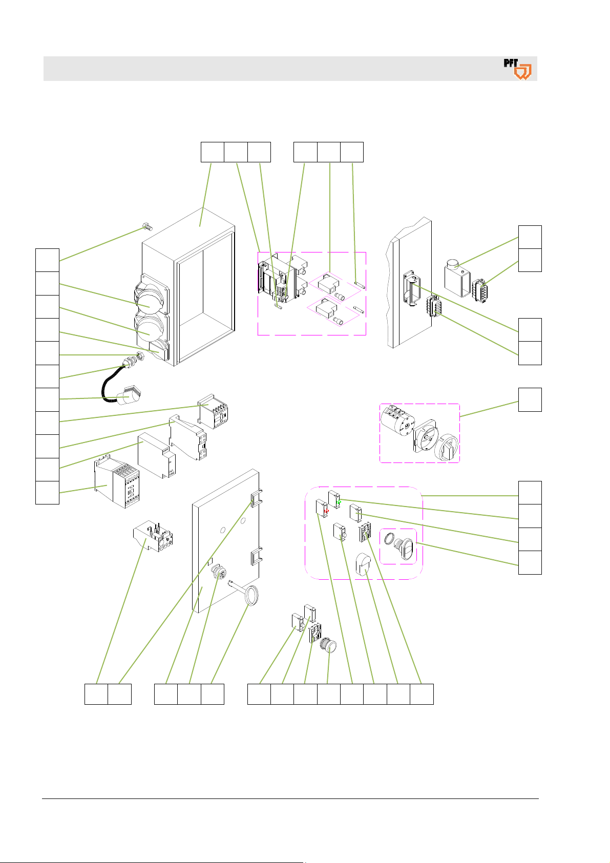
26.20 Control box HM 24 Art.No. 00008735
1 2 3 4 5 6
35
34
34
33
32
31
30
29
28
27
26
7
8
9
10
11
12
25 24 23 22 21 18 14 16 20 19 18 17 16
48
2017-08-07
13
14
15

Item Qty. Art.No. Description
1
2
3
4
5
6
7
8
9
10
11
12
13
14
15
16
17
18
19
20
21
22
23
24
25
26
27
28
29
30
31
32
33
34
35
1 00 02 21 13 Empty housing HM 104 RAL 7032/structure
1 00 02 21 38 Transformer 400 V - 42 V 70 VA
1 20 41 90 21 Fuse 5 x 20, 2.0 A
1 00 01 24 75 Fuse cap round/black bayonet socket
2 20 41 92 50 Fuse link TRKS 4/1-SI (5x30)
1 00 08 72 53 Fuse 5 x 30, 0,63A
1 20 42 98 23 Socket housing HAN 10A 10 pins angled
1 20 42 98 22 Male insert small 10 pins HAN 10A
1 20 42 98 21 Socket housing 10 poles, HAN 10A
1 20 42 98 24 Female insert 10 pins, HAN 10A
1 20 45 52 00 Main reversing switch, cpl.
1 00 05 59 54 Luminous push-button key on/off cpl. M22
1 00 05 38 35 Contact-element 1 make contact M 22
2 00 05 38 86 LED - resistor - additional series resistor 42 V
1 00 05 38 32 Luminous push-button key on/off M 22
2 00 05 38 34 Fastening adapter M 22
1 00 05 38 31 Membranes angular for double pressure switch M22-TDD
1 00 05 38 81 Luminous element white 12-30V
1 00 05 38 36 Contact-element 1 break contact M 22
1 00 05 38 74 Front cap for the signal lamp yellow M 22
1 20 44 45 00 Key for control box
1 00 03 62 49 Lock for control box
1 00 04 31 13 Door HM 104 RAL7032
2 00 05 37 67 Hinge 180° cpl. for control box
1 00 08 53 76 Motor protection relay 6-10A type ZB12, construction size I
1 00 08 42 24 Air-break control DIL M15-10 42V
1 20 45 27 51 Phase sequence relay 200-500 V type FPF 2
1 20 45 27 00 Time lag relay 42V, 1,5-30 sec.
1 20 44 72 00 Contactor DIL ER 22, 42V
1 00 02 20 63 Plug solenoid valve
2 00 04 11 41 Connector skintop with nut M16 x 1.5
2 00 04 11 43 Counternut Skintop M 16 x 1.5
1 20 42 72 10 Panel mounted socket Schuko 16A grey
2 20 42 66 10 Panel mounted socket CEE 4 x 16A 6h red
4 20 20 87 01 Hex. screw M8 x 16 galv.
PFT SCREW MIXER HM 24 Overview – Operation – Spare Parts Lists
Spare parts drawing
For spare parts orders only with specification of the type plate!
2017-08-07
49

PFT SCREW MIXER HM 24 Overview – Operation – Spare Parts Lists
Spare parts drawing
26.21 Water Manifold Unit Art.No. 00002119 / 00211923
1 2 3 4 5 6 7 8 9 10 11 12
34
33
32
31
13
30
29
28
13
14
15
16
7
17
18
19
27
26
25
24
5
22 11 16 23 21
50
2017-08-07
20
21
22

PFT SCREW MIXER HM 24 Overview – Operation – Spare Parts Lists
Spare parts drawing
26.22 Spare parts list Water Manifold Unit Art.No. 00002119 / 00211923
Item Qty. Art.No. Description
1
2
3
4
5
6
7
8
9
10
11
12
13
14
15
16
17
18
19
20
21
22
23
24
25
26
27
28
29
30
31
32
33
34
1 00 00 21 19 Wasserarmatur HM 24
1 20 15 77 00 Needle valve 1/2" type 6701
1 20 15 78 00 Hand knob for needle valve 1/2"
1 20 20 36 12 Curved section 1/2" ext. thread galv.
2 20 20 54 00 Reducing nipple 1" ext. thread 1/2" int. thread galv.
1 00 00 22 92 Bracket for water flow meter HM 24 100-1000 l/h 200mm
5 20 20 72 00 Safety nut M 8 galv.
1 20 20 93 13 Washer B 8,4 galv.
1 20 20 87 01 Hex. screw M8 x 16 galv.
1 20 21 60 00 Gauge 0-10 bar 1/4" at bottom, D = 63mm
1 20 20 52 00 Reduction piece 1/2" ext. thread - 1/4" int. thread galv.
1 20 20 47 00 Angled distributor 1/2" int. thread, 4-way
3 20 20 17 00 Seal for Geka coupling (50 pieces)
2 20 20 09 00 Geka coupling 1/2" ext. thread with gasket
1 20 21 52 00 Tap 1/2" without drainer
2 20 20 34 01 Double nipple 1/2" X 60mm galv.
3 20 20 99 86 Steel bow M8 X 1"
1 00 00 21 21 Support for water manifold HM 22/24
1 20 15 20 00 Water inlet filter for Geka coupling
1 00 00 15 58 Pressure reducer D 06F 1/2"
2 20 20 31 07 Nipple 1/2" ext. thread flat with nut 3/4"
2 20 21 53 00 Tap 1/4" ext. thread with socket 10mm
1 00 45 64 51 Solenoid valve 1/2", 400V, 50/60Hz, type 6213 A
1 00 00 22 13 Water flow meter 100-1000l/h 250mm
2 20 18 45 10 Connection nut 1 1/2" for water flow meter 20184000
1 20 18 42 00 Cone for water flow meter type 1600/2500
2 20 18 43 00 O-ring D 34 x 3,5
2 20 18 46 00 Insertion piece 1"
2 20 18 47 00 Stop for part. no. 20 18 40 00, 20 18 49 00, 20 18 50 00
1 20 18 40 12 Plastic tube 100-1.000 l/h 200mm
1 20 20 15 00 Geka coupling 1/2"
2 00 05 91 96 Hose clamp 19-21
1 20 21 36 02 Water-/air hose 1/2" x 400mm
1 20 20 37 80 Hose socket 1/2" conical with nut 3/4" int. thread
For spare parts orders only with specification of the type plate!
2017-08-07
51

PFT SCREW MIXER HM 24 Overview – Operation – Spare Parts Lists
Spare parts drawing
26.23 Water pressure booster pump HM 24 cpl. Art. No. 00070238
1 2 3 4 5 4 6 7
19
18
17
16
15
8
9
10
11
14 13 12
52
2017-08-07

PFT SCREW MIXER HM 24 Overview – Operation – Spare Parts Lists
Spare parts drawing
26.24 Spare parts list water pressure booster pump HM 24 cpl. Art.No.
00070238
Item Qty. Art.No. Description
1
2
3
4
5
6
7
8
9
10
11
12
13
14
15
16
17
18
19
1 00 07 02 38 Water pressure booster pump HM 24 cpl.
1 20 20 17 00 Seal for Geka coupling (50 pieces)
1 20 20 16 00 Geka coupling 3/4" socket (packing unit = 10 pcs)
1 00 00 21 98 Water-/air hose 3/4" x 290mm
2 00 05 91 96 Hose clamp 19-21
1 20 19 04 43 Hose screw joint 1" ext. thread socket 3/4"
1 20 20 36 20 Curved section 1" int. thread-ext.thread galv.
1 00 23 13 67
Water pressure booster pump SL-AV3 PK a 37kW 230V
4 20 20 71 03 Hex. screw M6 x 20 galv.
4 20 20 93 00 Washer B 6,4 galv.
4 20 20 62 00 Safety nut M6 galv.
4 20 20 99 86 Steel bow M8 X 1"
2 20 20 72 00 Safety nut M8 galv.
1 00 00 97 69 Support for AV 3 at HM 22/24
1 20 15 20 00 Water inlet filter for Geka coupling
2 20 20 17 00 Gasket Geka-coupling (packing unit = 50 pieces)
1 20 20 09 10 Geka coupling 3/4" ext. thread
1 20 20 50 00 Reducing nipple 1" ext. thread-3/4" int. thread galv.
1 20 42 41 43 Motor connection cable 0,8m Schuko plug and cable lug
For spare parts orders only with specification of the type plate!
2017-08-07
53

PFT SCREW MIXER HM 24 Overview – Operation – Spare Parts Lists
Spare parts drawing
26.25 Water pressure booster pump AV1000 HM 24 Art. No. 00466201
1 2 3
12
11
10
4
9 8 7 6 5
14 13
54
2017-08-07

PFT SCREW MIXER HM 24 Overview – Operation – Spare Parts Lists
Spare parts drawing
26.26 Spare parts list water pressure booster pump HM 24 cpl. Art.No.
00070238
Item Qty. Art.No. Description
1
2
3
4
5
6
7
8
9
10
11
12
13
14
4 20 20 99 86 Steel bow M8 X 1"
1 20 19 04 43 Hose screw joint 1" ext. thread socket 3/4"
1 20 20 36 20 Curved section 1" int. thread-ext. thread galv.
1 20 20 16 81 High pressure coupling 3/4" ext. Thread with seal
1 00 27 19 87 Ball tap 1/8" Internal thread/external thread, one-side lever
1 20 56 53 27 Copper gasket D=10.5
1 00 49 30 84 Water pressure booster pump AV1000/1 230V 1Phase 50Hz
1 00 46 62 03 Support AV1000/1 HM 22/24 RAL2004
1 20 42 41 43 Motor connection cable 0,8m Schuko plug and cable lug
1 20 21 36 08 Water-/air hose 3/4" x 750mm
2 20 20 29 00 Hose clip 28-31 packing unit=10ST
1 20 20 16 80 High pressure coupling 3/4" socket with seal
8 20 20 72 00 Safety nut M8 galv.
2 20 20 63 23 Saucer-head screw M8 x 25 galv.
For spare parts orders only with specification of the type plate!
2017-08-07
55

PFT SCREW MIXER HM 24 Overview – Operation – Spare Parts Lists
Spare parts drawing
26.27 Spare parts list AV1000/1 400V 60Hz Art.No. 00491839
1 2 3 4 5 6 7 8 9
10
11
12
27 26 25 24 23 22
13
14
15
16
17
18
19
20
21
56
2017-08-07

PFT SCREW MIXER HM 24 Overview – Operation – Spare Parts Lists
Spare parts drawing
26.28 Spare parts list AV1000/1 400V 60Hz Art.No. 00492679
Item Qty. Art.No. Description
1 1 On request Nozzle
2 4 On request Screw
3 1 On request Cover
4 4 On request Screw
5 1 On request Terminal board
6 1 On request Bearing cap rear
7 4 On request Screw
8 1 On request Fan
9 1 On request Fan hood
10 1 On request Compensating spring
11 1 On request Grooved ball bearing
12 1 On request Shaft with rotor
13 1 On request Grooved ball bearing
14 1 On request Arrester
15 1 On request Motor housing with winding (230/400V)
16 1 On request Support foot
17 1 On request Bearing cover front
18 3 On request Screw
19 1 On request Cover pump body
20 1 On request O-ring for pump body
21 1 00467107 Face seal for AV 1000
22 1 On request Wheel- und Diffuser set
23 1 On request O-ring for pump body
24 1 On request Washer
25 1 On request Nut for wheel
26 4 On request Screw for pump body
27 1 On request Screw with O-ring
For spare parts orders only with specification of the type plate!
2017-08-07
57

PFT SCREW MIXER HM 24 Overview – Operation – Spare Parts Lists
Circuit Diagramm 60Hz
27 Circuit Diagramm 60Hz
58
2017-08-07

PFT SCREW MIXER HM 24 Overview – Operation – Spare Parts Lists
Circuit Diagramm Cable set 00002127
28 Circuit Diagramm Cable set 00002127
2017-08-07
59
PFT SCREW MIXER HM 24 Overview – Operation – Spare Parts Lists
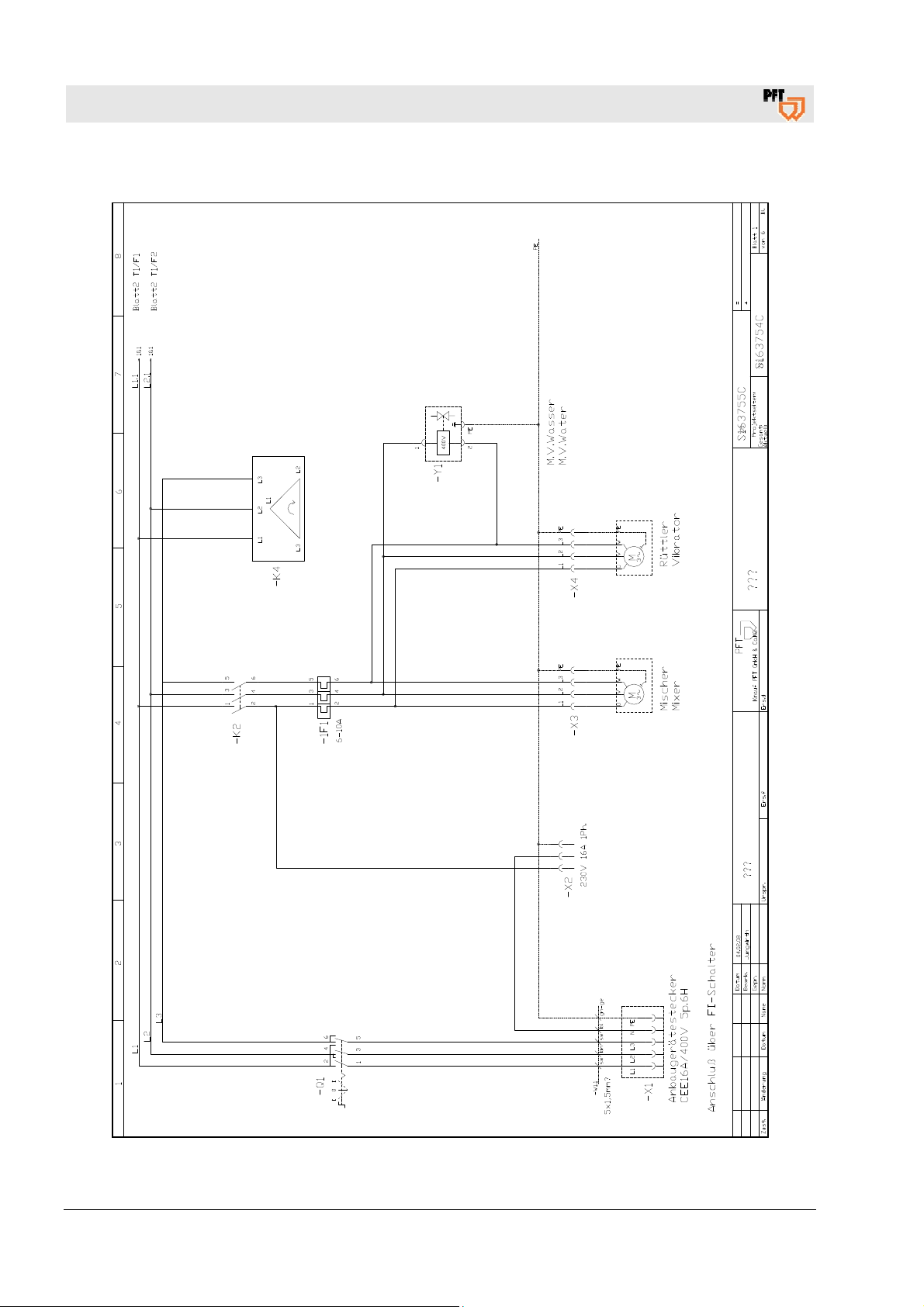
Circuit Diagramm HM 24 S163754C
29 Circuit Diagramm HM 24 S163754C
60
2017-08-07

PFT SCREW MIXER HM 24 Overview – Operation – Spare Parts Lists
Circuit Diagramm HM 24, 230 V, 3 phases 60 Hz
30 Circuit Diagramm HM 24, 230 V, 3 phases 60 Hz
2017-08-07
61

PFT SCREW MIXER HM 24 Overview – Operation – Spare Parts Lists
62
2017-08-07

PFT SCREW MIXER HM 24 Overview – Operation – Spare Parts Lists
2017-08-07
63

PFT SCREW MIXER HM 24 Overview – Operation – Spare Parts Lists
PFT – THE FLOW OF PRODUCTIVITY
Knauf PFT GmbH & Co. KG
Postfach 60 97343 Iphofen
Einersheimer Straße 53 97346 Iphofen
Deutschland
Telefon +49 9323 31-760
Telefax +49 9323 31-770
Technische Hotline +49 9323 31-1818
info@pft-iphofen.de
www.pft.eu
64
2017-08-07
 Loading...