

Page 1
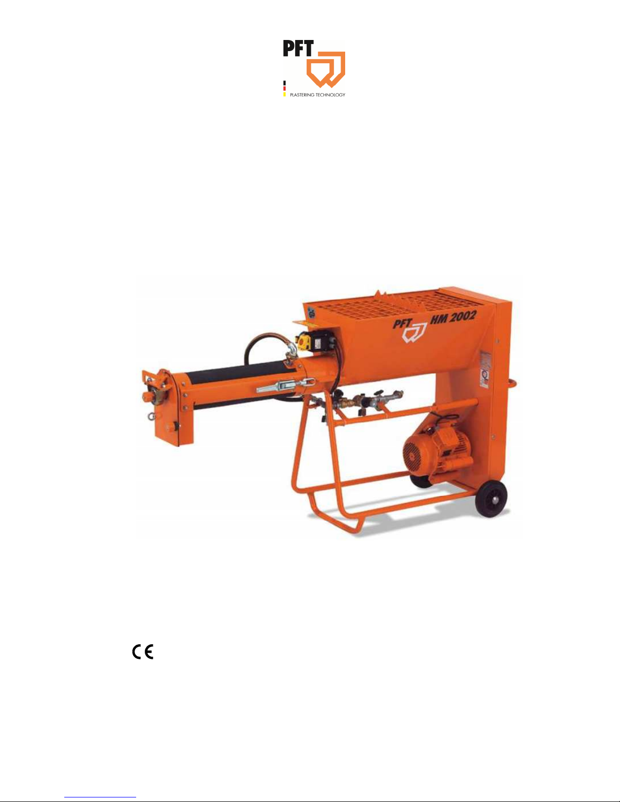
Table of Contents
2017-03-14
Operating manual
PFT continuous mixer HM 2002
Overview - Operation - Spare parts lists
Article number of the operating manual: 20 09 98 59
HM 2002 article number 20 54 60 03
HM 2002 with rubber mixing tube article number 00 02 04 73
HM 2002 rubber mixing tube 2.2 KW 120 V 60 Hz 1 Phase article number 00 59 33 59
Read the operating manual prior to starting any work!
Page 2

2
2017-03-14
© Knauf PFT GmbH & Co. KG
P.O. Box no. 60 97343 Iphofen
Einersheimer Straße 53 97346 Iphofen
Germany
Tel.: +49 9323 31-760
Fax: +49 93 23 31-770
Technical hotline +49 9323 31-1818
[email protected]
www.pft.eu
Page 3

PFT continuous mixer HM 2002 Overview - Operation - Spare parts lists
Table of Contents
2017-03-14
3
1 EC Declaration of Conformity ..................... 5
2 Examination .................................................. 6
2.1 Examination by machine operator ........... 6
2.2 Periodic inspection ................................... 6
3 General information ..................................... 6
3.1 Information regarding the operating
manual ................................................. 6
3.2 Keep the manual for future reference ...... 7
3.3 Division .................................................... 7
4 Technical data .............................................. 7
4.1 General information ................................. 7
4.2 Connection value of water ....................... 8
4.3 Power connection values 230 V 50 Hz .... 8
4.4 Power connection values 230 V 60 Hz .... 8
4.5 Power connection values 120 V 60 Hz .... 9
4.6 Operating conditions ................................ 9
5 Sound power level ....................................... 9
6 Vibrations ..................................................... 9
7 Dimension sheet HM 2002 ........................ 10
8 Name plate .................................................. 10
9 Quality Control sticker .............................. 10
10 Structure of HM 2002 ................................. 11
10.1 Overview of HM 2002 .......................... 11
10.2 Water fitting .......................................... 12
10.3 Retrofit kit for water flow meter 100 -
1,000 l/h for HM 2002 ........................ 12
10.4 Rubber mixing tube art.no. 00012594 . 13
10.5 Mixing shaft .......................................... 13
10.6 Dosing shaft ......................................... 13
11 Connections ............................................... 13
11.1 Power connection 230 V 50 Hz ........... 13
11.2 Power connection 230 V 60 Hz ........... 14
11.3 Power connection 120 V 60 Hz ........... 14
12 Accessories ................................................ 15
13 Brief description ......................................... 16
13.1 CONTINUOUS MIXER PFT HM 2002 . 16
14 Material: ....................................................... 16
14.1 Fields of application .............................. 16
14.2 Advantages at a glance ........................ 17
15 Safety rules ................................................. 17
16 Transport, packing and storage................ 18
16.1 Safety instructions for transport ........... 18
16.2 Transport inspection ............................. 19
16.3 Transport in individual parts ................. 19
16.4 Transport of machine in operation ....... 19
17 Packaging .................................................... 20
18 Operation ..................................................... 20
18.1 Safety ................................................... 20
19 Preparing the machine ............................... 21
20 Connecting the power supply ................... 22
20.1 Power connection 230 V 50 Hz ............ 22
20.2 Power connection 230 V 60 Hz ............ 22
20.3 Power connection 120 V 60 Hz ............ 22
20.4 Danger to life from rotating parts .......... 22
21 Connecting the water supply .................... 23
21.1 Clean the strainer screen ..................... 23
21.2 Connecting the water hose................... 23
21.3 Water from water tank .......................... 24
22 Setting water factor .................................... 24
22.1 Pre-setting the water flow rate.............. 24
22.2 Connect the water hose to the mixing
tube .................................................... 25
23 Hazardous dusts......................................... 25
24 Feeding dry material to the machine ........ 25
25 Putting the machine into operation .......... 26
25.1 Switching on the machine at 230 V ...... 26
25.2 Switching on the machine at 120 V ...... 26
Page 4

PFT continuous mixer HM 2002 Overview - Operation - Spare parts lists
Table of Contents
4
2017-03-14
25.3 Check consistency of material ............. 26
26 Monitoring the machine............................. 26
27 Apply mortar ............................................... 27
28 Interruption of work ................................... 27
29 Switching off the machine......................... 27
29.1 Switching off HM 2002 230 V ............... 27
29.2 Switching off HM 2002 120 V ............... 27
30 Stopping in case of an emergency ........... 28
30.1 Emergency-stop switch ........................ 28
31 Action in case of power cut ...................... 28
31.1 Disconnect power supply. .................... 28
32 Work on troubleshooting .......................... 29
32.1 Reaction in the event of faults .............. 29
32.2 Faults ................................................... 29
32.3 Safety ................................................... 29
32.4 Table of faults ....................................... 30
33 Measures to be taken in case of water
outage .......................................................... 31
34 Cleaning ...................................................... 31
34.1 Secure against restarting ..................... 31
35 End of work / clean machine ..................... 32
35.1 Empty mixing tube................................ 32
35.2 Disconnect power connection 230 V.... 32
35.3 Disconnect power connection 120 V.... 32
35.4 Secure against restarting ..................... 33
35.5 Clean HM 2002 .................................... 33
35.6 Cleaning the mixing shaft ..................... 33
35.7 Cleaning the mixing tube ..................... 34
35.8 Clean the material container ................ 34
35.9 Cleaning the dosing shaft .................... 35
35.10 Setting the mixing shaft ..................... 35
36 Measures in case of risk of frost .............. 35
36.1 Measures in case of risk of frost .......... 36
37 Maintenance ............................................... 36
37.1 Safety ................................................... 36
37.2 Remove connection cable ................... 37
37.3 Maintenance plan ................................ 38
38 Maintenance work ...................................... 38
38.1 Strainer screen .................................... 38
38.2 Lubrication ........................................... 39
38.3 Changing the V-belt ............................. 39
38.4 Actions after completed maintenance . 40
39 Disassembly ............................................... 40
39.1 Safety ................................................... 40
39.2 Disassembly ........................................ 41
40 Disposal ...................................................... 41
41 ET drawing / ET list of HM 2002 ............... 42
41.1 Material container with frame .............. 42
41.2 Gear motor ........................................... 44
41.3 Mixing tube HM complete, art.no.
00002116 ........................................... 46
41.4 Mixing tube HM rubber, art.no.
00012594 ........................................... 48
41.5 Cable set 120 V 60 Hz art.no.
00593375 ........................................... 50
41.6 Water fitting HM 2002 .......................... 52
41.7 Retrofit kit for water flow meter 100 -
1,000 l/h for HM 2002 ........................ 54
42 Index............................................................ 56
Page 5
PFT continuous mixer HM 2002 Overview - Operation - Spare parts lists
EC Declaration of Conformity
2017-03-14
5
1 EC Declaration of Conformity
Company:
Knauf PFT GmbH & Co. KG
Einersheimer Straße 53
97346 Iphofen
Germany
declares under our sole responsibility that the product:
Type of machine: HM 2002
Type of equipment: Horizontal continuous mixer
Serial number:
Guaranteed sound power level: 78 dB
is in conformity with the following CE directives:
• Outdoor directive (2000/14/EC),
• Machine directive (2006/42/EC),
• Electromagnetic Compatibility Directive (2014/30/EU).
Operative Conformity Assessment according to Outdoor Directive 2000/14/EC:
Internal production control as per article 14 paragraph 2 in connection with annex V.
This declaration only refers to the machine in the state in which it has been placed on the market. Parts
subsequently added by the user and/or subsequent interventions are not covered. This declaration ceases to
be valid if the product is converted or changed without consent.
Person authorised to compile the relevant technical documentation:
Dipl.-Wirtsch.-Ing. (FH) Michael Duelli, Einersheimer Straße 53, 97346 Iphofen.
The technical documentation is available from:
Knauf PFT GmbH & Co. KG, Technical Department, Einersheimer Straße 53, 97346 Iphofen.
Iphofen, Dr. York Falkenberg
Managing Director
Place, Date of issue Name and signature Identification of the signatory
Page 6

PFT continuous mixer HM 2002 Overview - Operation - Spare parts lists
Examination
6
2017-03-14
2 Examination
2.1 Examination by machine operator
Prior to each shift, the machine operator has to examine the
effectiveness of the control and safety devices as well as the
proper fitting of the protection devices.
The safe working condition of construction machinery has to be
checked by the machine operator during operation.
If the safety devices show any defects or if any other defects are
detected that compromise a safe operation, the supervisor has to
be informed immediately.
In case of defects that cause harm to persons, the operation of the
construction machine has to be stopped to eliminate the defects.
2.2 Periodic inspection
Construction machinery has to be inspected for their safe working
condition in accordance with the operating conditions and the
operational requirements as needed, however at least once a year
by an expert.
Pressure vessels have to undergo the prescribed expert
inspections.
The inspection results have to be documented and kept at least
until the next inspection.
3 General information
3.1 Information regarding the operating manual
This operating manual gives important information on handling the
device. A prerequisite for safe working is the observance of all
stated safety guidelines and instructions.
Furthermore the local accident prevention guidelines and general
safety instructions for the application area of the device are to be
adhered to.
Read the operating manual thoroughly before starting any work! It
is a part of the product and has to be kept near the tool and easily
accessible to the staff at all times.
If the tool is given to third parties, also include the operating
manual.
The figures in this manual are for presentation purposes of facts
not necessarily to scale and may slightly differ from the actual
model of the device.
Page 7
PFT continuous mixer HM 2002 Overview - Operation - Spare parts lists
Technical data
2017-03-14
7
3.2 Keep the manual for future reference
The operating manual has to be available during the whole service
life of the product.
3.3 Division
The operating manual is divided into 2 books:
Part 1 Safety
General safety instructions about HM
Article number: 00 14 63 78
Part 2 Overview, operation, service and spare parts lists (this
volume).
For safe operation of the device both parts have to be read and
observed. Together they form one operating manual.
4 Technical data
4.1 General information
Dimensions
Detail Value Unit
Weight: Art. No. 20 54 60 03 125 kg
Weight: Art. no. 00 02 04 73 118 kg
Weight: Art. no. 00 59 33 59 120 kg
Length 1870 mm
Width 575 mm
Height 1005 mm
Outlet height 560 mm
Hopper dimensions
Detail Value Unit
Container volume approx. 110 litres
Performance data
Detail Value Unit
Mixing performance approx.* 24 - 30 l/min
Grain size max. 4 mm
*Standard values depending on mortar quality, mortar composition,
mortar consistency. The guidelines of the mortar manufacturer are
ultimately authoritative.
Page 8
PFT continuous mixer HM 2002 Overview - Operation - Spare parts lists
Technical data
8
2017-03-14
4.2 Connection value of water
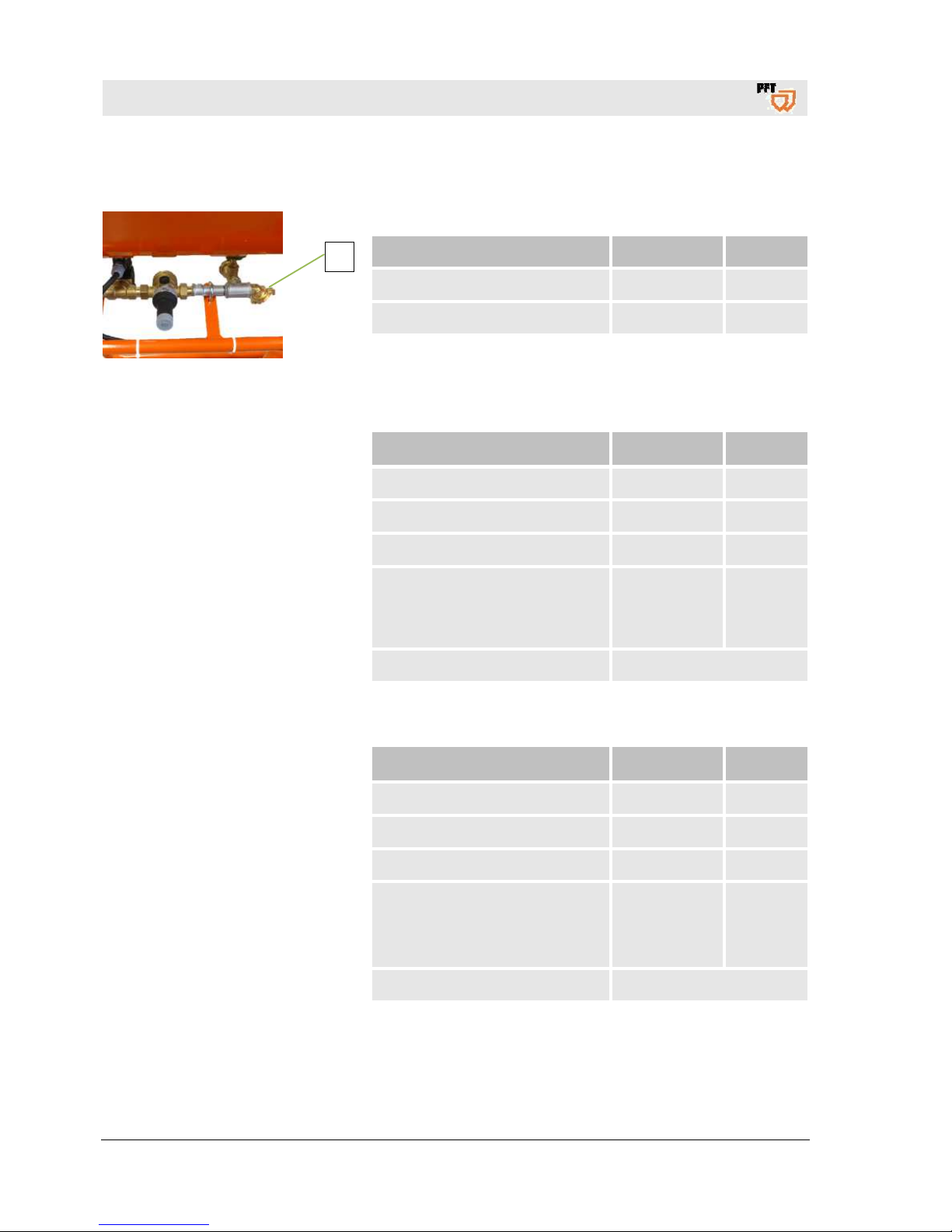
Fig. 1: Water connection
Detail Value Unit
Operating pressure, min. 2.5 bar
Connection (1) 1/2 inch
4.3 Power connection values 230 V 50 Hz
Electric 230 V 50 Hz
Detail Value Unit
Voltage, 1 Ph. 50 Hz 230 V
Power consumption, max. 14.5 A
Speed of mixing shaft 280 rpm
AC current 230 V / 50 Hz, 16 A
supply 3 x 2.5 mm² only to site
main cabinet with specified RCCB
30 mA
16 A
Fuse protection, at least 16 A type B
4.4 Power connection values 230 V 60 Hz
Electric 230 V 60 Hz
Detail Value Unit
Voltage, 1 Ph. 60 Hz 230 V
Power consumption, max. 13 A
Speed of mixing shaft 325 rpm
CEE connection, 3-pin (2P/PE)
supply 3 x 2.5 mm² only to site
main cabinet with specified RCCB
30 mA
16 A
Fuse protection, at least 16 A type B
1
Page 9

PFT continuous mixer HM 2002 Overview - Operation - Spare parts lists
Sound power level
2017-03-14
9
4.5 Power connection values 120 V 60 Hz
Electrics 120 V 60 Hz
Detail Value Unit
Voltage, 1 Ph. 60 Hz 120 V
Power consumption, max. 25 A
Speed of mixing shaft 325 rpm
CEE connection, 3-pin (2P/PE)
supply 3 x 4 mm² only to site main
cabinet with specified RCCB 30
mA
32 A
Fuse protection, at least 32A type C
4.6 Operating conditions
Environment
Detail Value Unit
Temperature range 2-45 °C
Relative humidity, max. 80 %
Duration
Detail Value Unit
Max. operating time at a stretch 8 hours
5 Sound power level
Guaranteed sound power level LWA 78 dB (A)
6 Vibrations
Weighted effective value of acceleration to which the upper body parts are exposed <2.5 m/s²
Page 10
PFT continuous mixer HM 2002 Overview - Operation - Spare parts lists
Dimension sheet HM 2002
10
2017-03-14
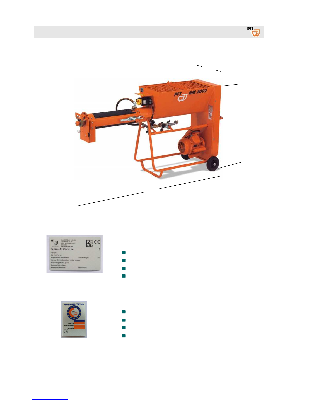
7 Dimension sheet HM 2002
Fig. 2: Dimension sheet
8 Name plate
Fig. 3: Name plate
The type plate is located on the front side of the material container
on the motor side and includes the following information:
Manufacturer
Type
Year of manufacture
Machine number
9 Quality Control sticker
Fig. 4: Quality Control sticker
The following details can be found on the Quality Control sticker:
CE confirmed as per EU directives
Serial no / serial number
Controller / signature
Date of control
1005
575
1870
Page 11
PFT continuous mixer HM 2002 Overview - Operation - Spare parts lists
Structure of HM 2002
2017-03-14
11
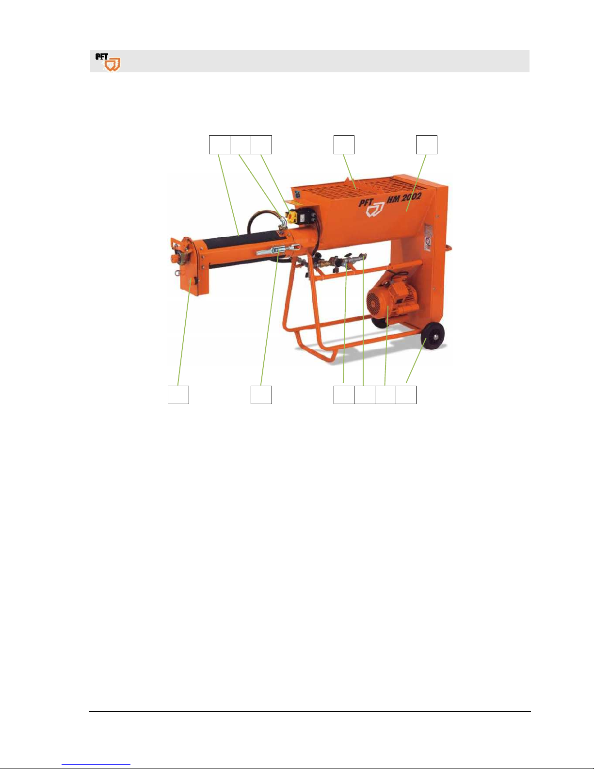
10 Structure of HM 2002
10.1 Overview of HM 2002
1 2 3 4 5
11 10 9 8 7 6
Fig.5: Overview of HM 2002
1. Rubber mixing tube
2. Water to mixing tube
3. ON / OFF switch
4. Protective grille with sack opener
5. Material container with frame
6. Wheel
7. Mixing motor
8. Water inlet, water connection from water supply
9. Water fitting
10. Quick closure at mixing tube
11. Mortar outlet
Page 12
PFT continuous mixer HM 2002 Overview - Operation - Spare parts lists
Structure of HM 2002
12
2017-03-14
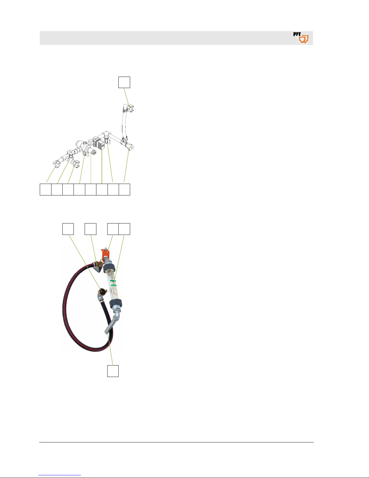
10.2 Water fitting
1
8 7 6 3 5 4 3 2
Fig. 6: Water fitting
1. Water connection to mixing tube.
2. Needle valve to adjust the water quantity.
3. Water drain valve (in case of risk of frost).
4. Solenoid valve.
5. Pressure reducer.
6. Water extraction.
7. Water extraction valve.
8. Water inlet from water supply or water pump.
10.3 Retrofit kit for water flow meter 100 - 1,000 l/h for HM 2002
1 2 3 4
5
Fig. 7: Retrofit kit for water flow meter
1. Water connection to mixing tube.
2. Needle valve to adjust the water quantity.
3. Attachment to material container.
4. Water flow meter 100-1000 l/h.
5. Connection to angular distributor with ball valve.
Page 13
PFT continuous mixer HM 2002 Overview - Operation - Spare parts lists
Connections
2017-03-14
13
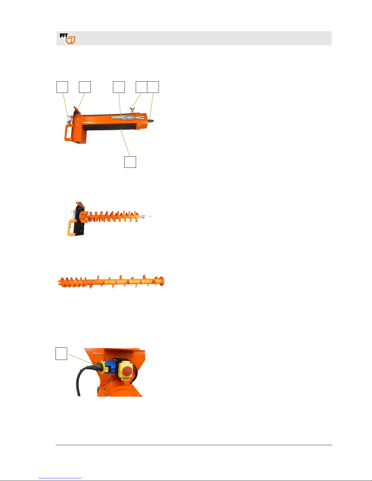
10.4 Rubber mixing tube art.no. 00012594
1 2 3 4 5
6
Fig.8: Rubber mixing tube
1. Square external bearing.
2. Removable star plate for mortar outlet flange.
3. Quick closure.
4. Water inlet at mixing tube.
5. Mixing shaft.
6. Rubber mixing tube.
10.5 Mixing shaft
Fig. 9: Mixing shaft
1. Sprocket mixing shaft HM 2002 (4 levels) article number
00431198 without mortar outlet flange.
10.6 Dosing shaft
Fig. 10: Dosing shaft
1. Dosing shaft 30 l/min for HM 2002 Article number 20547300
11 Connections
11.1 Power connection 230 V 50 Hz
Fig. 11: Power connection 230 V
1. Alternating current connection (1) 230 V.
1
Page 14

PFT continuous mixer HM 2002 Overview - Operation - Spare parts lists
Connections
14
2017-03-14
11.2 Power connection 230 V 60 Hz
Fig. 12: Power connection 230 V
1. Alternating current connection (1) 230 V 60 Hz.
11.3 Power connection 120 V 60 Hz
Fig. 13: Power connection 120 V
1. Alternating current connection (1) 120 V 60 Hz.
1
1
Page 15
PFT continuous mixer HM 2002 Overview - Operation - Spare parts lists
Accessories
2017-03-14
15
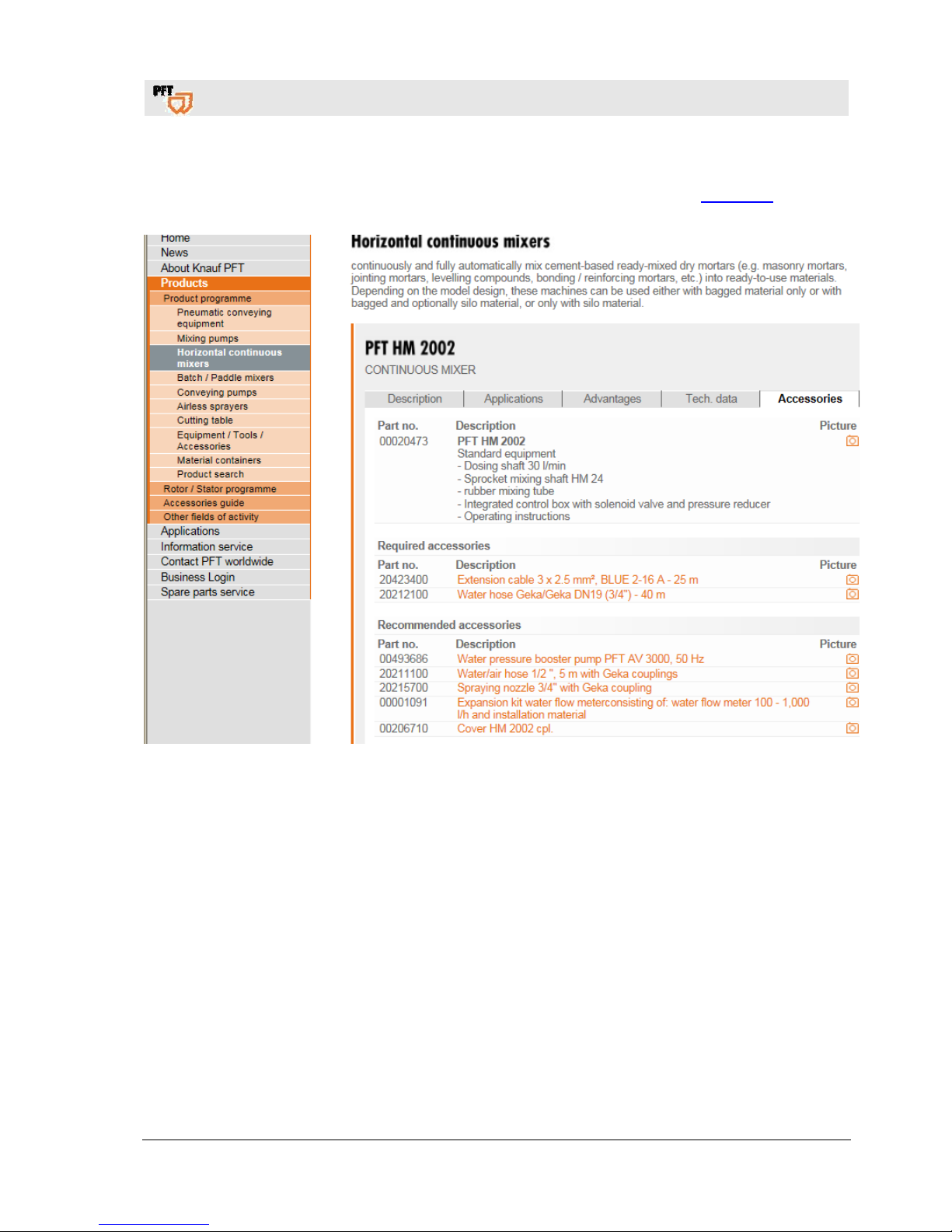
12 Accessories
Recommended accessory / equipment, PFT machines and device catalogue or under www.pft.eu.
Page 16
PFT continuous mixer HM 2002 Overview - Operation - Spare parts lists
Brief description
16
2017-03-14
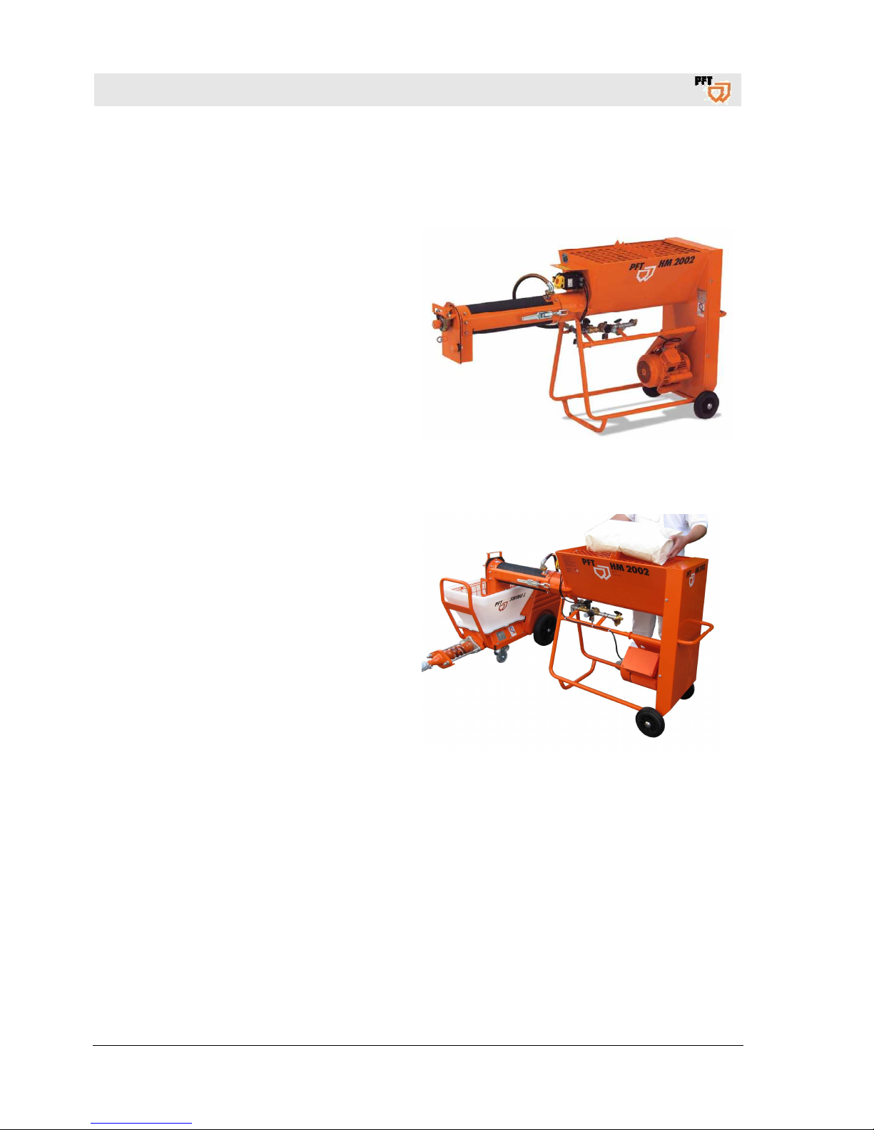
13 Brief description
13.1 CONTINUOUS MIXER PFT HM 2002
CONTINUOUS MIXER
PFT HM 2002
The compact bagged goods mixer PFT HM 2002
for alternating current with high performance.
quickly operational, reliable, easy to use
Thanks to the rubber mixing tube, there is hardly
any caking and the mixer is almost self-cleaning.
14 Material:
14.1 Fields of application
CONTINUOUS MIXER
PFT HM 2002
Mixes all bagged premixed dry mortars fully
automatically with a lime and cement base up to a
maximum 4 mm grain size such as:
• masonry mortar
• Light masonry mortar
• Adhesive and reinforcement mortar
• Flow and joint mortar
• cement plasters
• Finishing plaster
• Grater plaster
• insulation plasters
• Levelling compounds
etc.
Page 17
PFT continuous mixer HM 2002 Overview - Operation - Spare parts lists
Safety rules
2017-03-14
17
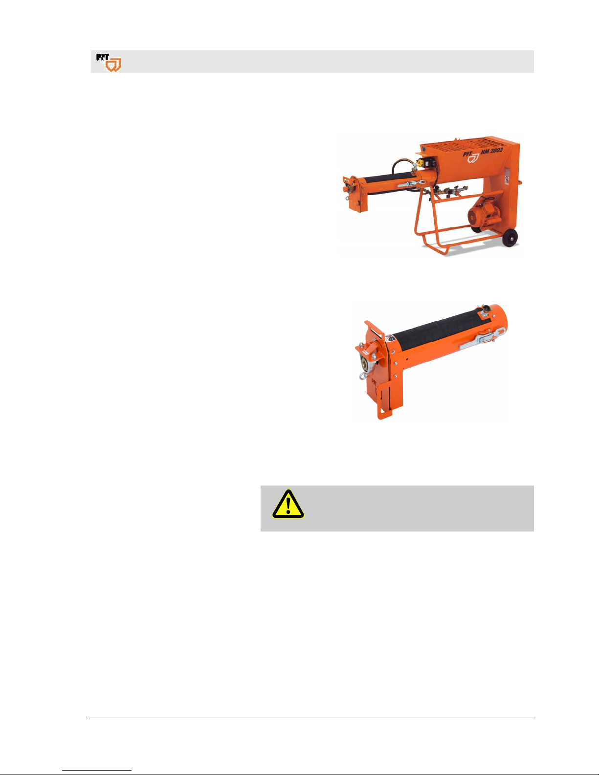
14.2 Advantages at a glance
robust construction
easy operation
minimum maintenance and cleaning expense
smooth trouble-free operation
low filling height
comfortable transportation
maintenance-free square external bearing
protected quick closure
New PFT rubber mixing tube for all continuous mixers
best suitable for processing adhesive mortar
no long-term caking of material
improved mixing quality
easy and thorough cleaning
low wear
cost-effective wear parts
can be retrofitted to current PFT continuous mixers
15 Safety rules
Caution!
Observe the regional safety rules for mortar
conveyors and mortar guns!
Page 18
PFT continuous mixer HM 2002 Overview - Operation - Spare parts lists
Transport, packing and storage
18
2017-03-14
16 Transport, packing and storage
16.1 Safety instructions for transport
Improper transport
ATTENTION!
Damage from improper transport!
Improper transport may cause substantial property
damage.
When unloading the packages on delivery as
well as transport within the company pay
attention and observe the symbols and
instruction on the package.
Use only the specified anchorage points.
Remove packaging only shortly before the
assembly.
Suspended loads
WARNING!
Danger to life from suspended loads!
When lifting heavy loads there is danger to life from
falling parts or uncontrolled swinging parts.
Therefore:
Never step under suspended loads.
Observe the instructions regarding the
provided anchorage points.
Do not fix to projecting machine parts or
eyelets of attached components.
Ensure safe fit of the sling gear.
Use only approved lifting gear and sling gear
with sufficient lifting capacity.
Page 19
PFT continuous mixer HM 2002 Overview - Operation - Spare parts lists
Transport, packing and storage
2017-03-14
19
16.2 Transport inspection
On receipt check the delivery immediately for completeness and
transport damage.
In case of externally visible transport damage, proceed as follows:
Do not accept the delivery or under reserve only.
Note the extent of damage on the transport documentation or
on the delivery note of the carrier.
NOTE!
Report any defect as soon as it is detected. Claims
for damages can be asserted only within the valid
warranty period.
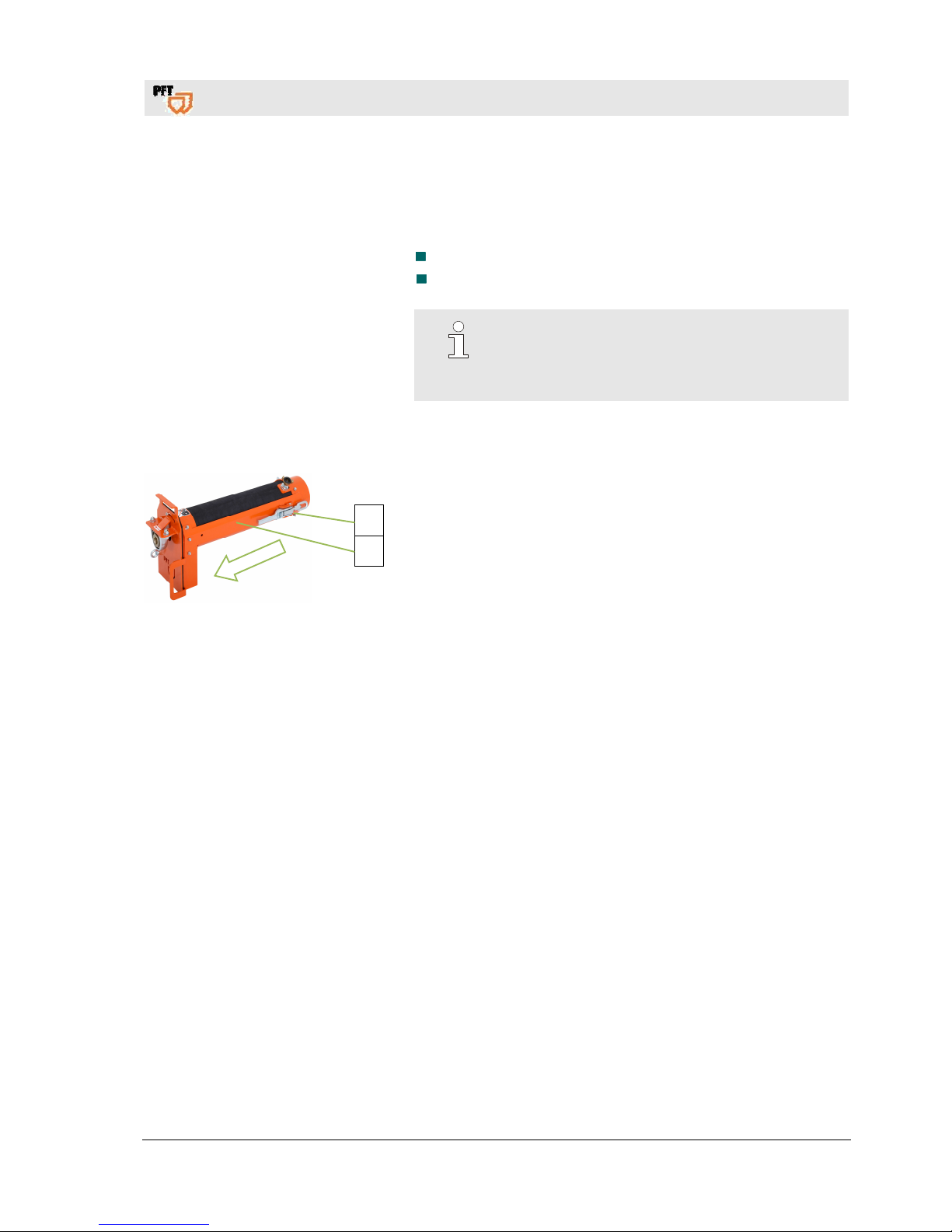
16.3 Transport in individual parts
Fig. 14: Transport
The mixing tube can be removed in order to make it easier to
transport the machine.
1. Release quick-release fasteners (1) and remove the mixing tube
(2) from the front.
16.4 Transport of machine in operation
Carry out the following steps before beginning the transport:
1. First unplug the mains cable.
2. Remove water supply line.
3. Start transport.
1
2
Page 20
PFT continuous mixer HM 2002 Overview - Operation - Spare parts lists
Packaging
20
2017-03-14
17 Packaging
For packaging The individual packages have to be packed in accordance with the
transport conditions to be expected. Only environmentally-friendly
materials were used for the packaging.
The packaging should protect the individual components until the
assembly from transport damage, corrosion and other damage.
Therefore do not destroy the packaging and remove only shortly
before the assembly.
Handling packaging materials If no agreement for the recovery of the packaging has been made,
separate materials according to type and size and reuse or recycle.
ATTENTION!
Environmental damage due to wrong disposal!
Packaging materials are valuable raw materials
and in many cases they can be reused or
reconditioned and recycled.
Therefore:
– Dispose of packaging materials in an
environmentally-friendly way.
– Observe the applicable local disposal
regulations. If required hand over the disposal
to a specialist.
18 Operation
18.1 Safety
Personal protective equipment
The following protective equipment has to be worn for all operative
work:
Protective clothing
Protective goggles
Protective gloves
Safety shoes
Hearing protection
NOTE!
Further protective equipment that is to be worn
when effective particular jobs will be pointed out
separately in the warning instructions of this
chapter.
Page 21
PFT continuous mixer HM 2002 Overview - Operation - Spare parts lists
Preparing the machine
2017-03-14
21
Basic information
WARNING!
Danger of injury due to incorrect operation!
Improper operation may lead to serious damage to
persons or property.
Therefore:
Carry out all operating steps according to the
instructions in this user manual.
Prior to starting your work, ensure that all covers
and protection devices are installed and work as
intended.
Never deactivate protection devices during
operation.
Ensure order and cleanliness in the work area!
Loose components and tools on top of one
another or lying about pose potential accident
risks.
Increased noise level may cause permanent
hearing deficiencies. At close range of the
machine 78 dB(A) can be exceeded due to
operational conditions. Close range is a distance
of less than 5 metres to the machine.
19 Preparing the machine
Prior to operating the machine carry out the following steps
for preparing the machine:
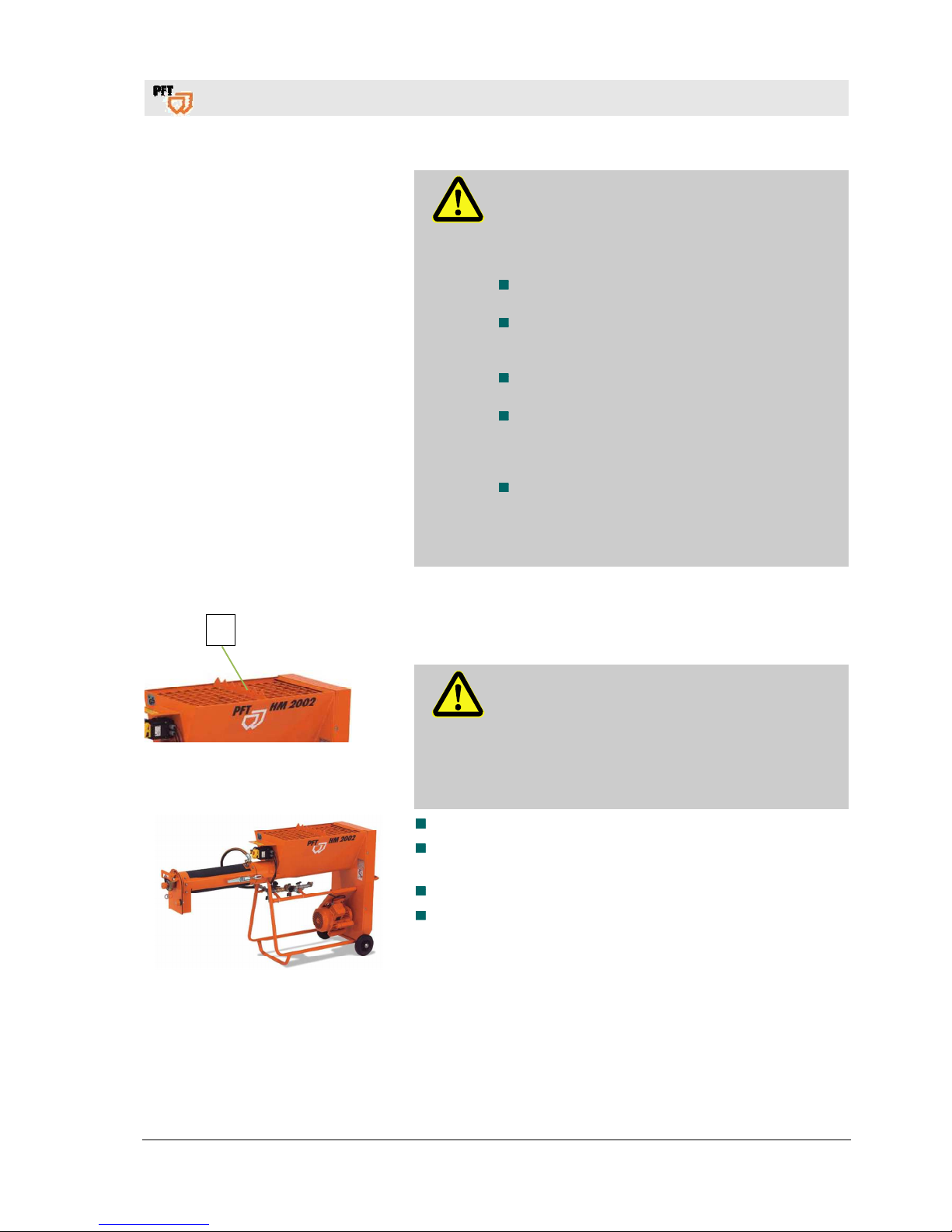
Fig. 15: Grille cover
DANGER!
Rotating dosing shaft!
Risk of injury when reaching into the material
container.
– During machine preparation and operation, the
grille cover (1) must not be removed.
– Never reach into the running machine.
Fig. 16: Set-up
The operating elements have to be freely accessible.
Put up the machine on a stable, even surface and secure
against unwanted movements:
Neither tilt nor roll off the machine.
Put up the machine in such a way that it cannot be hit by falling
objects.
1
Page 22
PFT continuous mixer HM 2002 Overview - Operation - Spare parts lists
Connecting the power supply
22
2017-03-14
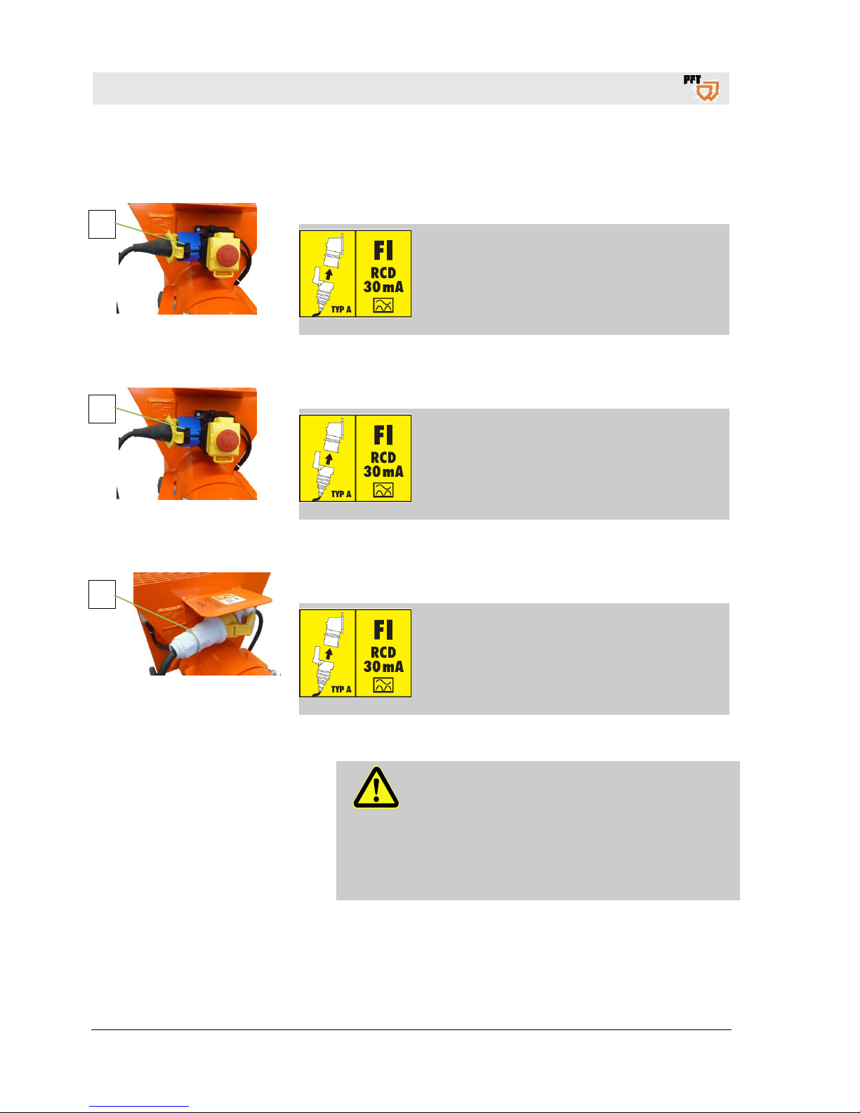
20 Connecting the power supply
20.1 Power connection 230 V 50 Hz
Fig. 17: Power connection
1. Connect the machine (1) only to a 230 V AC network.
DANGER!
Danger of death from electric current!
The connection line has to be fused properly:
Connect the machine only to a power source with
permissible RCCB (30 mA) RCD (residual
current operated device) type A.
20.2 Power connection 230 V 60 Hz
Fig. 18: Power connection
1. Connect the machine (1) only to a 230 V AC network.
DANGER!
Danger of death from electric current!
The connection line has to be fused properly:
Connect the machine only to a power source with
permissible RCCB (30 mA) RCD (residual
current operated device) type A.
20.3 Power connection 120 V 60 Hz
Fig. 19: Power connection
1. Connect the machine (1) only to a 120 V AC network.
DANGER!
Danger of death from electric current!
The connection line has to be fused properly:
Connect the machine only to a power source with
permissible RCCB (30 mA) RCD (residual current
operated device) type A.
20.4 Danger to life from rotating parts
WARNING!
Danger to life from rotating parts!
Improper operation may lead to serious damage to
persons or property.
The respective drive (motors) must be operated
only with the control cabinet of the machine.
Using other or external power sources is forbidden
for safety reasons.
1
1
1
Page 23
PFT continuous mixer HM 2002 Overview - Operation - Spare parts lists
Connecting the water supply
2017-03-14
23
21 Connecting the water supply
21.1 Clean the strainer screen
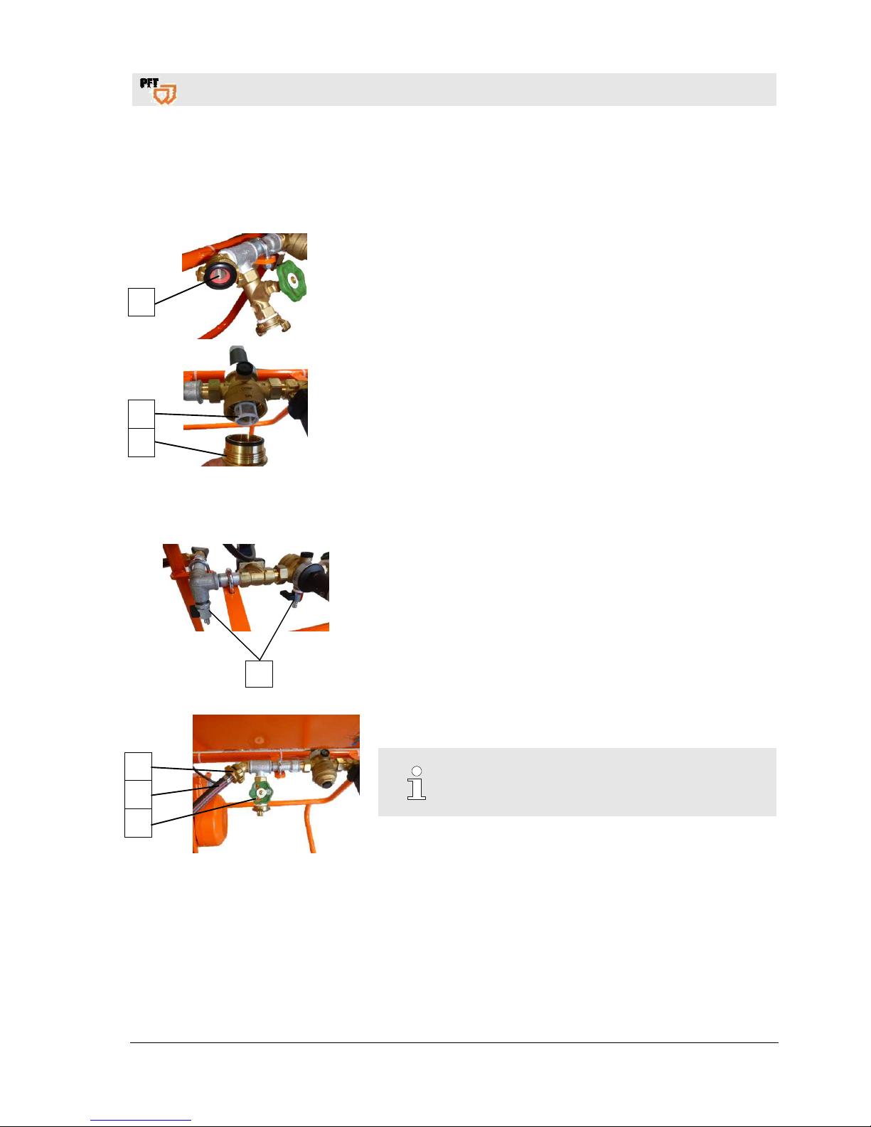
Fig. 20: Water inlet screen
1. Check whether the strainer screen in the water inlet (1) is clean.
2. If necessary, remove the strainer screen from the water inlet
and clean it.
Strainer screen with Geka coupling:
Article number 20152000
3. Remove the brass screen cup (2) from the pressure reducer.
4. Check whether the strainer screen in the pressure reducer (3) is
clean.
Screen for pressure reducer: Article number 20156000
5. Screw the brass cup (2) back.
21.2 Connecting the water hose
1
Fig. 21: Connecting the water hose
1. Close the water drain valves (1).
2. Clean and vent the water hose (2) of the water supply network
and connect it to the water inlet (3).
3. Open the water tap form the water supply line.
4. Open the water extraction valve (4).
5. As soon as water comes out at the water extraction valve (4),
close it again.
NOTE!
Use only clean water free of solids. The minimum
pressure is 2.5 bar when the machine is running.
1
3
2
3
2
4
Page 24
PFT continuous mixer HM 2002 Overview - Operation - Spare parts lists
Setting water factor
24
2017-03-14
21.3 Water from water tank
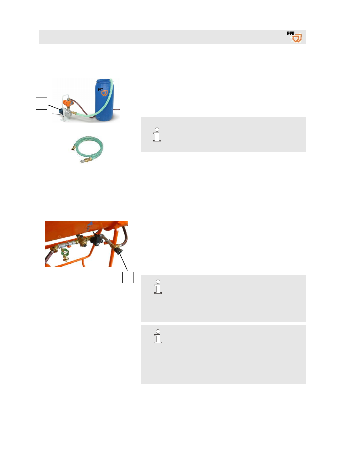
Fig. 22: Booster pump
Fig. 23: Suction strainer complete with
filter screen
Booster pump AV 3000, 230 V, 1 Ph, 50 Hz, 0.6 kW complete
article number 00493686
The connected booster pump ensures the required water pressure
of at least 2.5 bar.
NOTE!
When working from the water tank, the strainer
with filter screen (article number 00136619) has to
be positioned upstream (bleed booster pump).
22 Setting water factor
22.1 Pre-setting the water flow rate
1
Fig. 24: Needle valve
Adjust the expected amount of water at the needle valve (1):
1. Close the needle valve.
2. Then open the needle valve by two turns.
3. In this position, the water flow rate is approx. 200 ltr/h.
4. Using the needle valve, the material consistency can be
adjusted.
NOTE!
Turning the needle valve in clockwise direction
causes lesser water flow so that the material
becomes viscous and vice versa.
The specifications of the material manufacturer
must be observed here.
NOTE!
Any interruption in the mixing operation results in a
slight irregularity in the consistency of the material.
This irregularity normalises by itself as soon as the
machine has been working for a short while.
Therefore it is important not to change the water
quantity for each irregularity. Wait until the
consistency of the material has set again.
1
Page 25
PFT continuous mixer HM 2002 Overview - Operation - Spare parts lists
Hazardous dusts
2017-03-14
25
22.2 Connect the water hose to the mixing tube
1
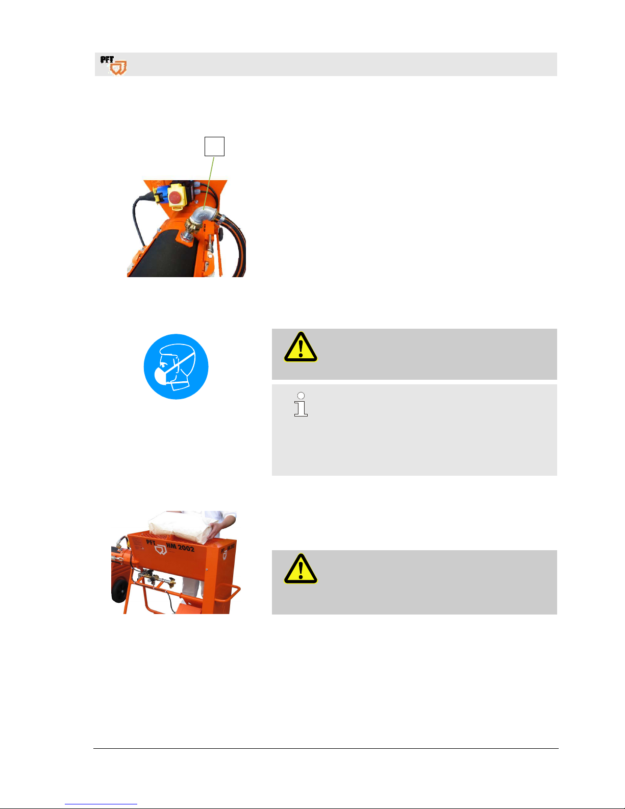
Fig. 25: Connecting the water hose
1. Connect the water hose to the mixing tube.
23 Hazardous dusts
Fig. 26: Dust protection
Warning!
Health hazard caused by dust!
In the long term, inhaled dust can lead to lung
damage or have other adverse health effects.
NOTE!
The machine operator or the person working in the
dusty area always have to wear a dust protection
mask when filling the machine!
The rules of the Committee on Dangerous
Substances (AGS) can be found under Technical
Rules for Dangerous Substances (TRGS 559).
24 Feeding dry material to the machine
Fig. 27: Fill the material container
1. Fill the bagged material into the material container.
DANGER!
Risk of injury at the sack opener!
The sharp edges of the sack opener pose a risk of
injury.
Wear safety gloves.
Page 26
PFT continuous mixer HM 2002 Overview - Operation - Spare parts lists
Putting the machine into operation
26
2017-03-14
25 Putting the machine into operation
25.1 Switching on the machine at 230 V
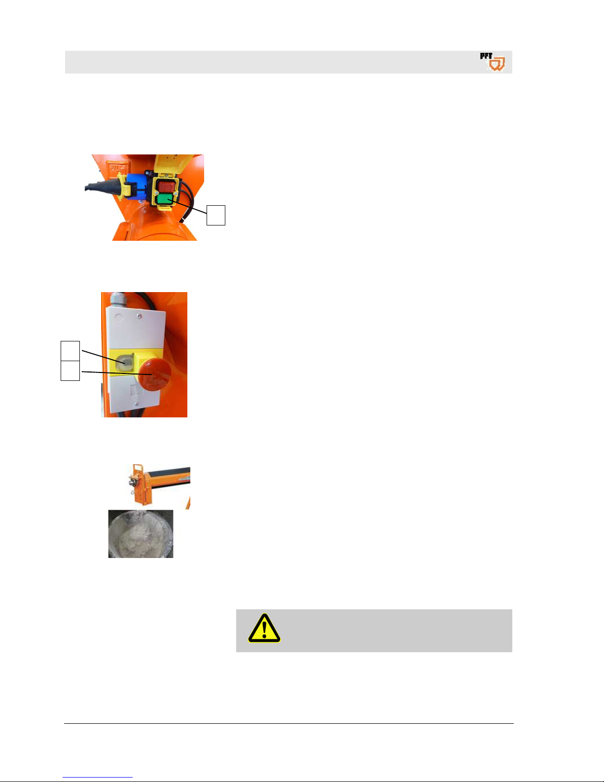
Fig. 28: Switching on at 230 V
1. Switch on the machine using the green switch.
25.2 Switching on the machine at 120 V
Fig. 29: Switching on at 120 V
1. Switch on the machine using the black switch (1).
2. EMERGENCY STOP button (2).
Turn the button to the right (in the direction of the arrow) to
loosen the button.
The machined is switched off in this pressed state.
25.3 Check consistency of material
Fig. 30: Material consistency
1. Check the consistency of material at the mortar outlet.
26 Monitoring the machine
DANGER!
Access by unauthorised persons!
The machine must be operated only if monitored.
1
1
2
Page 27
PFT continuous mixer HM 2002 Overview - Operation - Spare parts lists
Apply mortar
2017-03-14
27
27 Apply mortar
DANGER!
Risk of injury from discharged mortar!
Discharged mortar may lead to injuries to eyes and
face.
– Always wear protective goggles.
– Always position yourself in such a way that you
are not hit by the mortar being discharged.
28 Interruption of work
NOTE!
Always obs
erve the setting time of the material to be
processed:
Clean the mixing tube depending on the setting time
of the material and the duration of the interruption
(pay attention to outside temperature).
The guidelines of the material manufacturers have to
be observed regarding breaks.
29 Switching off the machine
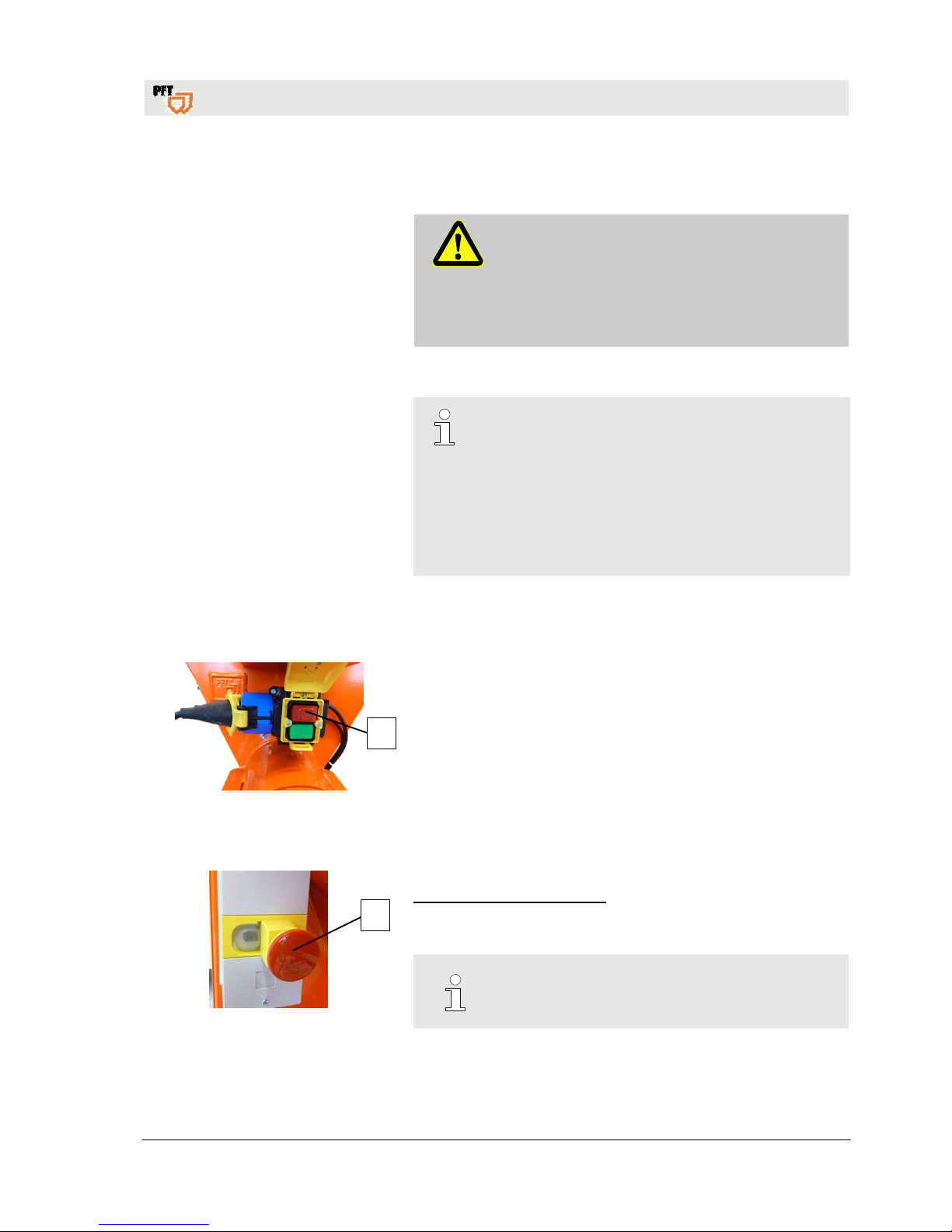
29.1 Switching off HM 2002 230 V
Fig. 31: Switching off at 230 V
1. Switch off the machine using the red switch.
29.2 Switching off HM 2002 120 V
Fig. 32: Switching off at 120 V
EMERGENCY STOP button:
1. Switch the machine off by pressing the red push button (1).
2. The machined is switched off in this pressed state.
NOTE!
Turn the button to the right (in the direction of the
arrow) to loosen the button.
1
1
Page 28
PFT continuous mixer HM 2002 Overview - Operation - Spare parts lists
Stopping in case of an emergency
28
2017-03-14
30 Stopping in case of an emergency
30.1 Emergency-stop switch
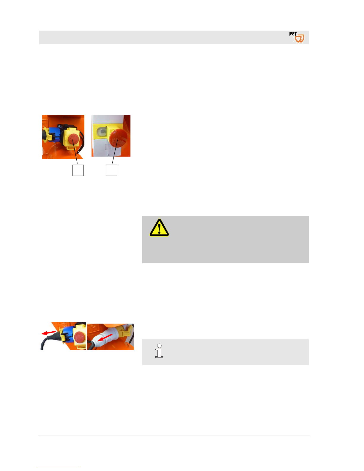
Stopping in case of an emergency In dangerous situation machine movements have to be stopped as
quickly as possible, and the power supply has to be disconnected.
1 2
Fig. 33: Stopping
In case of danger proceed as follows:
1. Switch off the machine by pressing the red push button (1).
2. Switch off the machine by pressing the red push button (2).
3. Disconnect power supply.
4. Inform responsible person at the operational site.
5. If necessary, call for medical assistance and a fire brigade.
6. Recover persons from the danger zone, initiate First Aid
measures.
7. Keep access routes free for emergency vehicles.
After the rescue operations
8. If the severity of the emergency permits inform the competent
authorities.
9. Assign specialised personnel with the troubleshooting.
WARNING!
Danger to life from premature reactivation!
On reactivation there is danger to life for all
persons in the danger zone.
Before reactivation ensure that there are no
persons in the danger zone anymore.
10. Check the system before reactivation and ensure that all safety
equipment is installed and functional.
31 Action in case of power cut
31.1 Disconnect power supply.
Fig. 34: Disconnect power supply.
1. Disconnect power supply.
2. Let qualified staff check the power supply.
NOTE!
The machine is equipped with a restart interlock.
The machine must be restarted after power failure.
Page 29
PFT continuous mixer HM 2002 Overview - Operation - Spare parts lists
Work on troubleshooting
2017-03-14
29
32 Work on troubleshooting
32.1 Reaction in the event of faults
The following strictly applies:
1. In the event of faults presenting immediate danger to persons
or property, activate the emergency OFF function immediately.
2. Determine cause for fault.
3. If the rectification of faults requires works in the danger zone,
switch off the system and secure against restarting.
4. Inform the manager on site immediately about the fault.
5. Depending on the type of fault commission authorised skilled
personnel or rectify the fault yourself.
NOTE!
The following fault table gives information on who
is authorised to rectify the fault.
32.2 Faults
The following chapter describes possible causes for faults and the
activities carried out for their rectification.
In case faults occur frequently, shorten the maintenance intervals
in accordance with the actual load.
In the event of faults that cannot be rectified by means of the
following notes, kindly contact the dealer.
32.3 Safety
Personal protective equipment
The following protective equipment has to be worn for all
maintenance work:
Protective clothing.
Protective goggles, protective gloves, safety shoes, ear
protection.
Page 30

PFT continuous mixer HM 2002 Overview - Operation - Spare parts lists
Work on troubleshooting
30
2017-03-14
Personnel
The work for rectification of faults described here can be carried
out by the operator, unless marked otherwise.
Some works must be carried out only by specially trained skilled
personnel or exclusively by the manufacturer. Information on
this can be found in the description of the individual faults.
Work on the electrical system must, in principle, be carried out
only by electricians.
32.4 Table of faults
Fault Possible cause Solution Rectification by
Machine does
not start
Current
Power supply not in order Repair power supply Service engineer
“On” switch not pressed Press the switch Operator
RCCB was triggered Reset RCCB Service engineer
Machine does
not start
Material
Excessively thickened material in
mixing tube
Empty the mixing tube and start
again
Operator
Excessively dry material in mixing
tube
Empty the mixing tube and start
again
Operator
Water is not
flowing
Solenoid valve (hole in membrane
blocked)
Clean solenoid valve Service engineer
Solenoid coil defective Change solenoid coil Service engineer
Water inlet on the middle body
blocked
Clean the water inlet on the middle
body
Operator
Needle valve closed Open needle valve Operator
Cable to solenoid valve defective Replace cable to solenoid valve Service engineer
Mixing motor
does not start
Mixing motor defective Replace the mixing motor Service engineer
Connection cable defective Change connection cable Service engineer
Machine
stops after a
short while
Water inlet screen contaminated Clean or replace strainer Operator
Hose connection or water pipe too
small
Increase dimensions of hose
connection or water pipe
Operator
Water inlet pipe too long or inlet
pressure too low
if possible, attach an additional
booster pump
Service engineer
Page 31
PFT continuous mixer HM 2002 Overview - Operation - Spare parts lists
Measures to be taken in case of water outage
2017-03-14
31
Mortar flow
ceases
Bad mixture in mixing tube Add more water Operator
Material is clumped and narrows
the water inlet
Remove the material and clean the
water inlet
Operator
Material in material container has
become wet
Remove the wet material and dry
the material container
Operator
Mixing shaft defective Replace the mixing shaft Operator
Mortar flow
‘thick-thin’
Too little water
Increase the water quantity by 10%
for approx. ½ minute and then turn
down slowly
Operator
Mixing shaft defective; no original
PFT agitator
Replace the mixing shaft with
original PFT agitator
Operator
Pressure reducer set incorrectly or
defective
Adjust or replace pressure reducer Service engineer
33 Measures to be taken in case of water outage
NOTE!
Water can be supplied to the machine from a
container by means of a booster pump (article
number 00493686) (see page 24 point 22.3)
34 Cleaning
34.1 Secure against restarting
DANGER!
Danger to life from unauthorised restarting!
When working with the machine there is the risk
that the energy supply is switched on without
authorisation. This poses a danger to life for the
persons in danger area.
– Switch off all energy supplies before starting
any work and secure against restarting.
Page 32
PFT continuous mixer HM 2002 Overview - Operation - Spare parts lists
End of work / clean machine
32
2017-03-14
35 End of work / clean machine
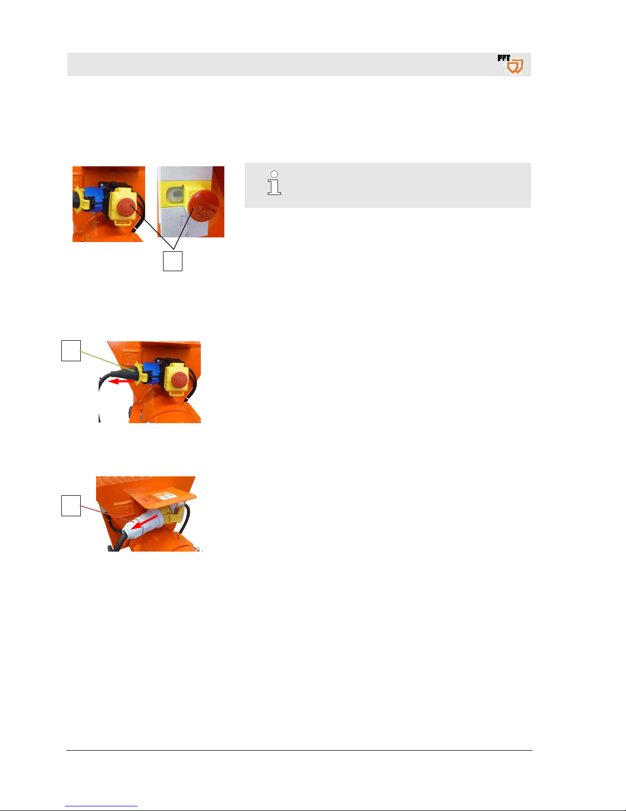
35.1 Empty mixing tube
1
Fig. 35: Switching off
NOTE!
In case of a continuous daytime operation, the
machine is cleaned only at the end of work.
The machine has to be cleaned daily after work:
1. Stop filling material into the material container shortly before
end of work.
2. As soon as diluted material emerges from the mortar outlet,
switch off the machine by pressing the red push button (1).
3. Switch the machine on again and collect the thinned material
into a separate container.
35.2 Disconnect power connection 230 V
Fig. 36: Power cable
1. Unplug power cable 230 V (1).
35.3 Disconnect power connection 120 V
Fig. 37: Power cable
1. Unplug power cable 120 V (1).
1
1
Page 33
PFT continuous mixer HM 2002 Overview - Operation - Spare parts lists
End of work / clean machine
2017-03-14
33
35.4 Secure against restarting
DANGER!
Danger to life from unauthorised restarting!
When working with the machine there is the risk that
the energy supply is switched on without
authorisation. This poses a danger to life for the
persons in danger area.
Switch off all power supplies before starting any
work and secure against restarting.
If protective covers have been removed for
cleaning purposes, they must be properly put back
again without fail after completion.
35.5 Clean HM 2002
ATTENTION!
Water can enter sensitive machine parts!
Before cleaning the machine cover all openings in
which no water must enter for safety and functional
reasons (e.g. electric motors and control cabinets).
NOTE!
Do not direct the water jet on electrical parts such as
gear motor or ON/OFF switch.
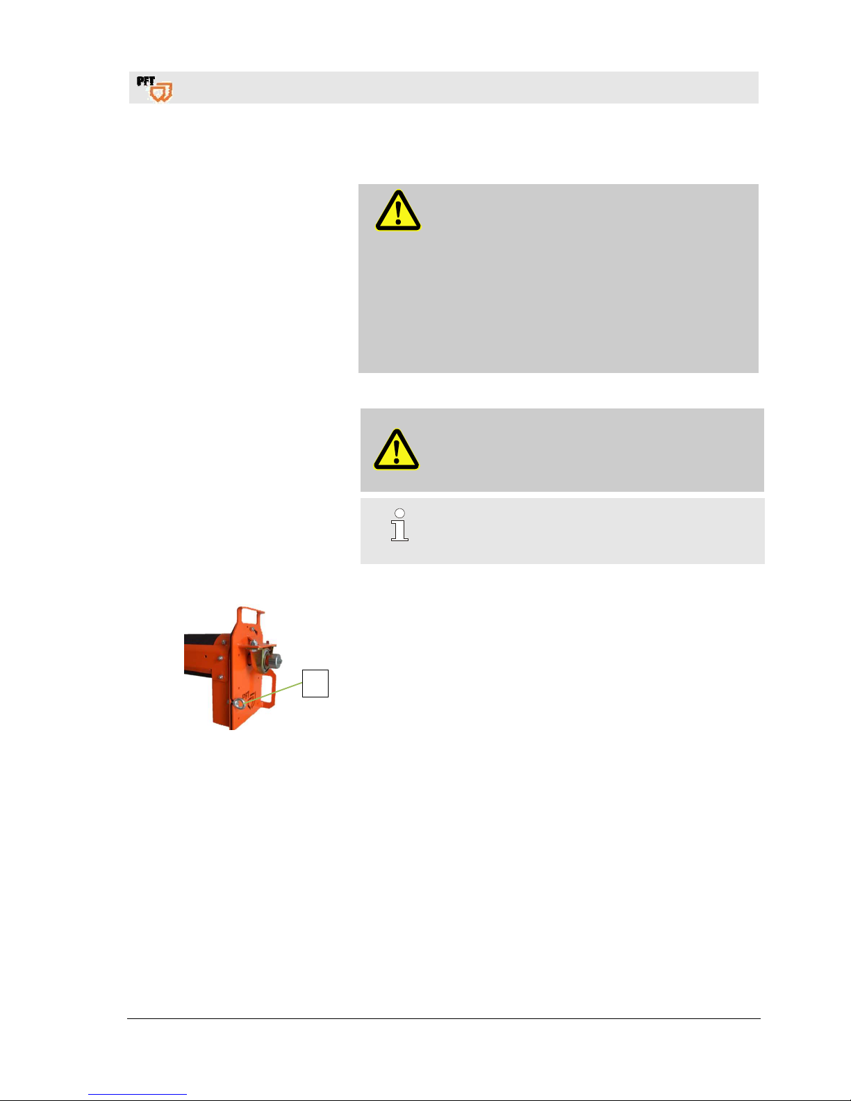
35.6 Cleaning the mixing shaft
Fig. 38: Loosen ring nut
1. Loosen ring nut (1).
1
Page 34
PFT continuous mixer HM 2002 Overview - Operation - Spare parts lists
End of work / clean machine
34
2017-03-14
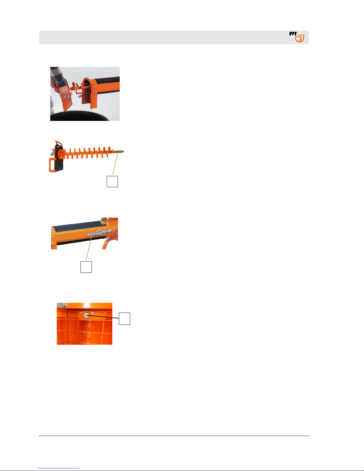
Fig. 39: Remove the mixing shaft
2. Turn the star plate to the left. Pull it forward from the mixing tube
with the mixing shaft and clean.
2
Fig. 40: Cleaning the mixing shaft
3. Slightly lubricate the bearing journal (2) of the mixing shaft after
cleaning.
35.7 Cleaning the mixing tube
1
Fig. 41: Cleaning the mixing tube
1. Open the quick closures (1) on both sides of the mixing tube.
2. Remove and clean the rubber mixing tube.
35.8 Clean the material container
Fig. 42: Clean the material container
1. Clean the material container with water only when it is completely
empty.
2. Loosen the screw (1).
3. Remove the protective grille.
1
Page 35
PFT continuous mixer HM 2002 Overview - Operation - Spare parts lists
Measures in case of risk of frost
2017-03-14
35
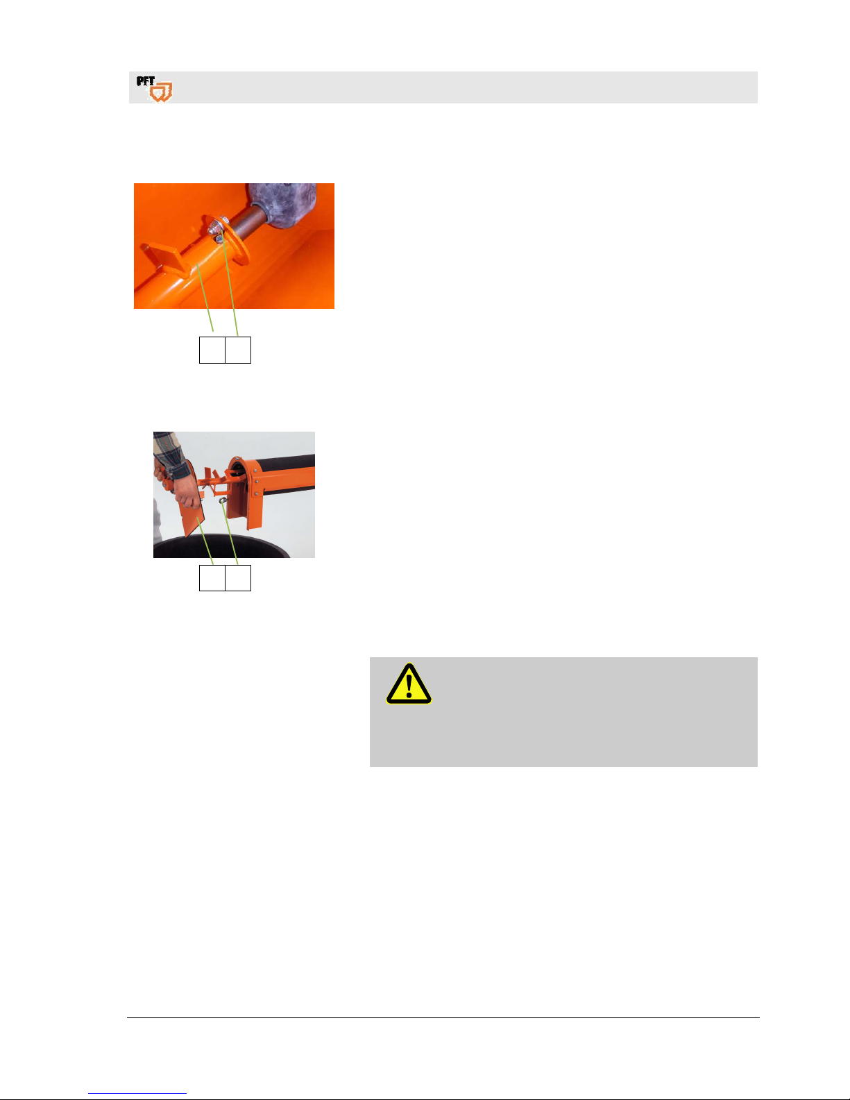
35.9 Cleaning the dosing shaft
2 1
Fig. 43: Cleaning the dosing shaft
1. Loosen the nuts of the screw (1).
2. Remove the dosing shaft (2) and clean it.
3. Reinsert the cleaned dosing shaft and secure with nuts and the
screw.
4. Set the protective grille and secure it.
35.10 Setting the mixing shaft
2 1
Fig. 44: Setting the mixing shaft
1. Assemble clean and dry parts only.
2. Keep the quick closures at the mixing tube clean.
3. Move the cleaned mixing shaft into the mixing tube and connect
with dosing shaft.
4. Fasten the star plate (2) using the ring nut (1).
36 Measures in case of risk of frost
ATTENTION!
Damage by frost!
Water that expands inside the machine during frost
can cause severe damage.
– The following steps are to be carried out if the
machine stands still in case of risk of frost.
Page 36
PFT continuous mixer HM 2002 Overview - Operation - Spare parts lists
Maintenance
36
2017-03-14
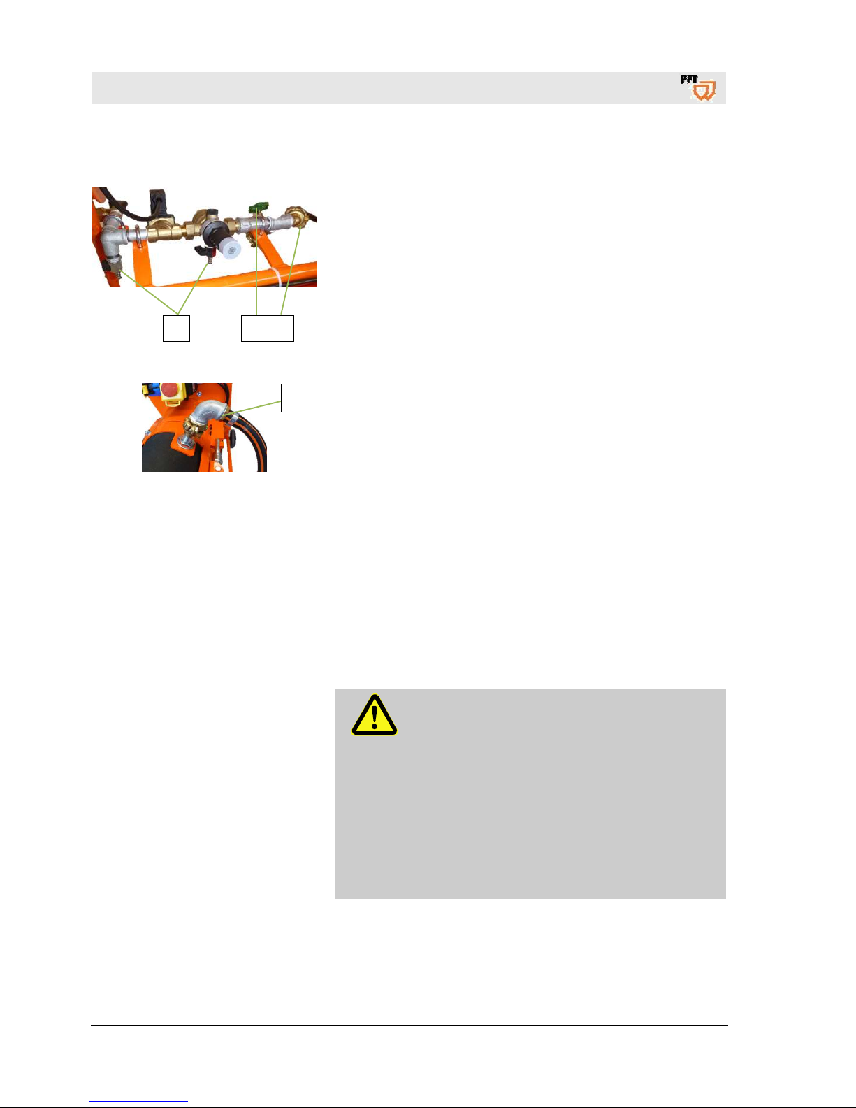
36.1 Measures in case of risk of frost
2 3 1
Fig. 45: In case of risk of frost
1. Disconnect the water hose (1) from the water inlet.
2. Open the ball valves (2) and water extraction valve (3).
Fig. 46: Disconnecting the water hose
3. Disconnect the water hose (4) from the water inlet at the mixing
tube.
37 Maintenance
37.1 Safety
Personnel
The maintenance works described here can be carried out by
the operator, unless marked otherwise.
Some maintenance work must only be carried out by specially
trained technical personnel or exclusively by the manufacturer.
Work on the electrical system must, in principle, be carried out
only by electricians.
Basic information
WARNING!
Risk of injury due to improperly carried out
maintenance work!
Improper maintenance can lead to severe injuries
or considerable property damage.
Therefore:
Ensure order and safety at the assembly site!
Loose, stacked components or components lying
about can cause accidents.
If components were removed, ensure proper
assembly, put back all fastening elements and
observe torque indications for screws.
4
Page 37
PFT continuous mixer HM 2002 Overview - Operation - Spare parts lists
Maintenance
2017-03-14
37
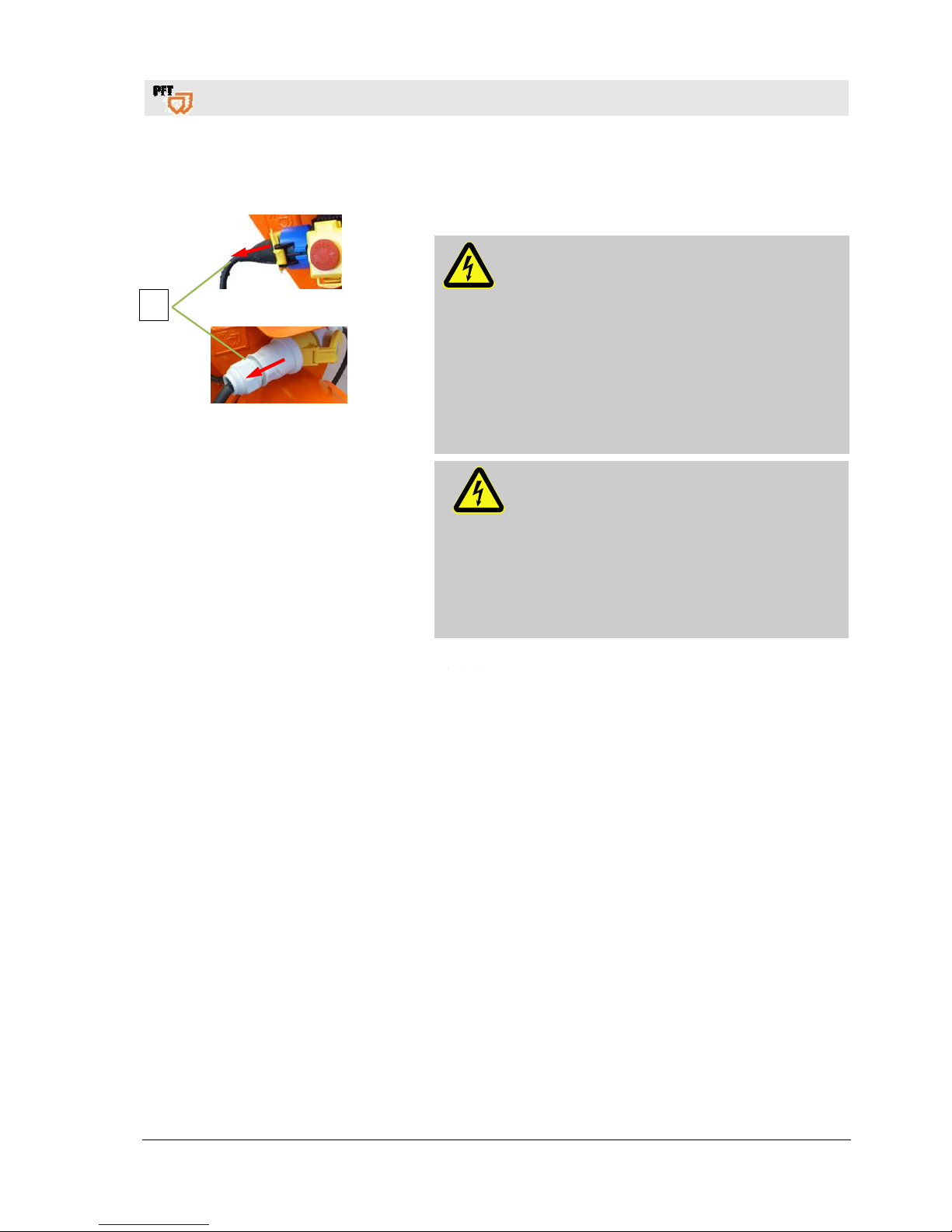
37.2 Remove connection cable
Fig. 47: Disconnect power supply
1. Disconnect power supply
DANGER!
Danger of death from electric current!
There is danger to life if you come in contact with
live parts. Activated electrical components can
carry out uncontrolled movements and cause
serious injuries.
Therefore:
Switch off the energy supply before starting any
work and secure against restarting.
Disconnect the power supply by removing the
connection cable (1).
Electrical system
DANGER!
Danger of death from electric current!
There is danger to life if you come in contact
with electrical components. Activated electrical
components can carry out uncontrolled
movements and cause serious injuries.
Therefore:
– Switch off the energy supply before starting
any work and secure against restarting.
Environmental protection
Observe the following notes on environm ental protection when carryi ng out mainten ance works:
Remove the discharged, exhausted or surplus grease at all
greasing points that are lubricated manually and dispose of
in accordance with the local applicable regulations.
Collect replaced oil in suitable containers and dispose of in
accordance with the local applicable regulations.
1
Page 38
PFT continuous mixer HM 2002 Overview - Operation - Spare parts lists
Maintenance work
38
2017-03-14
37.3 Maintenance plan
The following paragraphs describe the maintenance works that are
require for an ideal and trouble-free operation.
In the event that increased wear is detected during regular checks,
the required maintenance intervals have to be shortened according
to the actual signs of wear.
Should you have any queries regarding maintenance works and
intervals contact the manufacturer, see page 2 for service
addresses.
Interval Maintenance work To be carried out by
daily Clean/replace strainer screen in water inlet. Operator
38 Maintenance work
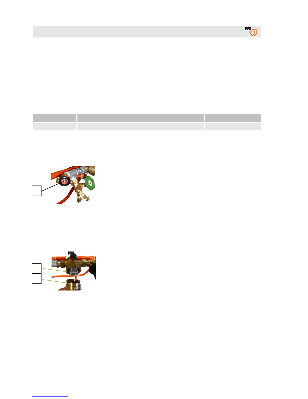
38.1 Strainer screen
Fig. 48: Strainer screen in water inlet.
Check the strainer screen in water inlet daily:
1. Remove the strainer screen (1) from Geka coupling.
2. Clean the strainer screen.
3. Replace the sieve in case of heavy contamination.
4. Reinsert the strainer screen.
Strainer screen with Geka coupling:
Article number 20152000
Implementation by operator.
38.1.1 Strainer screen in pressure reducer
Fig. 49: Strainer screen in pressure
reducer
1. Remove the closure cap (1) from the pressure reducer.
2. Take out the strainer screen (2) and clean (monthly).
3. Replace the screen in case of heavy contamination.
4. Insert screen and screw on the closure cap.
Screen for pressure reducer: Article number 20156000
Execution by service technician.
1
2
1
Page 39
PFT continuous mixer HM 2002 Overview - Operation - Spare parts lists
Maintenance work
2017-03-14
39
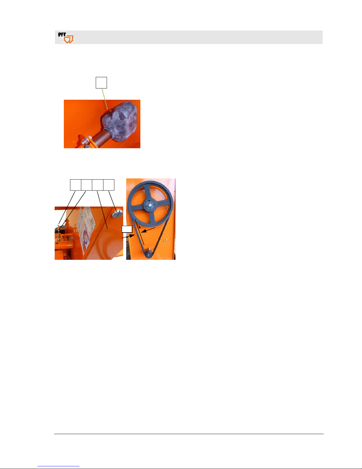
38.2 Lubrication
1
Fig. 50: Lubrication
Lubricate the bearings for the dosing shaft at the lubricating nipple
(1) once in six months.
Implementation by operator.
38.3 Changing the V-belt
Fig. 51: V-belt
1. Loosen the four screws (1) and remove the cover
hood (2).
2. Loosen the counter nuts (3) and screws (4).
3. The V-belt is tensioned by the dead weight of the
gear motor.
4. The indentation depth should not be more than one
centimetre.
4 3 2 1
1 cm
Page 40

PFT continuous mixer HM 2002 Overview - Operation - Spare parts lists
Disassembly
40
2017-03-14
38.4 Actions after completed maintenance
1. After finishing the maintenance works and prior to switching on
the machine, the following steps have to be carried out:
2. Check all previously loosened screw connections for secure fit.
3. Check if all previously removed safety systems and covers are
properly reinstalled.
4. Ensure that all used tools, materials and other equipment were
removed from the work area.
5. Clean the work area and remove any spilled materials such as
liquids, processing material or similar.
6. Ensure that all safety systems of the installation work perfectly.
39 Disassembly
After the useful service life has been reached, the device has to be
dismantled and disposed of in an environmental-friendly manner.
39.1 Safety
Personnel
Disassembly must be carried out only by specially trained
technical personnel.
Work on the electrical system must be carried out by qualified
electricians only.
Basic information
WARNING!
Risk of injury in case of improper disassembly!
Stored residual energies, sharp components, points
or edges at and inside the device or at the required
tools might cause injuries.
Therefore:
Prior to starting the works ensure that there is
sufficient space.
Carefully handle components with sharp edges.
Ensure order and cleanliness at the working place!
Loose components and tools on top of one
another or lying about pose potential accident
risks.
Dismantle components correctly. Pay attention to
partly high dead weight of the components. If
required use lifting equipment.
Secure components that they do not fall down or
fall over.
In case of doubt, consult the dealer.
Page 41
PFT continuous mixer HM 2002 Overview - Operation - Spare parts lists
Disposal
2017-03-14
41
Electrical system
DANGER!
Danger of death from electric current!
There is danger to life if you come in contact with live
parts. Activated electrical components can carry out
uncontrolled movements and cause serious injuries.
Therefore:
Prior to beginning the disassembly, switch off the
power supply and finally disconnect it.
39.2 Disassembly
Clean the device for phasing out and disassemble under
observance of applicable health and safety rules as well as
environmental regulations.
Prior to starting the disassembly:
Switch off device and secure against restarting.
Physically separate the complete energy supply to the device,
discharge stored residual power.
Remove operating supplies as well as remaining processing
materials and dispose of in an environment-friendly way.
40 Disposal
If no agreement for the recovery or the disposal was made, recycle
the disassembled components:
Scrap metals.
Recycle plastic elements.
Dispose of remaining components, sorted according to the type
of material.
ATTENTION!
Environmental damage in case of incorrect
disposal!
Waste from electronic and electrical equipment,
electronic components, lubricants and other
auxiliary materials are subject to hazardous waste
treatment and must be disposed of by specialised
companies only!
The local authority or special waste management operators can
supply information on environmentally-friendly disposal.
Page 42
PFT continuous mixer HM 2002 Overview - Operation - Spare parts lists
ET drawing / ET list of HM 2002
42
2017-03-14
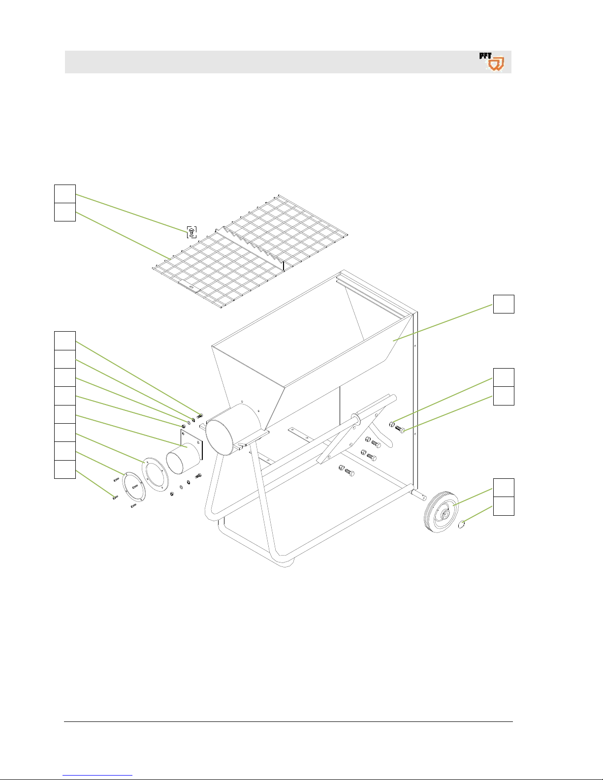
41 ET drawing / ET list of HM 2002
41.1 Material container with frame
1
2
3
4
5
15
14
13
12
11
10
9
8
7
6
Page 43

PFT continuous mixer HM 2002 Overview - Operation - Spare parts lists
ET drawing / ET list of HM 2002
2017-03-14
43
ITEM Qty Article no. Article description
1
1 20 54 63 10 Material container HM 2002 with frame RAL 2004
2
4 20 20 89 00 Safety nut M12 galvanised
3
4 20 20 68 01 Hex. screw M12 x 30 galvanised
4
2 20 54 83 10 Wheel 180 x 50 x 90
5
2 20 20 86 03 Quick fastener with cap 20s x N 2 7
6
4 20 20 96 11 Countersunk screw with hexagon socket M4 x 12, galvanised
7
1 20 54 95 15 Clamping flange for mixing tube gasket HM2/200/2002
8
1 20 54 80 10 Rubber gasket D154 x D107 x 5
9
1 20 54 71 03 Dosing wear tube HM 200/2002 D102 x 145
10
2 20 20 72 00 Safety nut M8 galvanised
11
2 20 20 93 13 Washer B 8.4, galvanised
12
2 20 20 93 14 Serrated washer A 8.4, galvanised
13
2 20 20 61 00 Hex. screw M8 x 20 galvanised
14
1 20 54 62 00 Protective grille of HM 2000/2002 RAL 2004
15 1 00 21 45 19 Retainer washer and hex. screw M8x25 complete with groove
Page 44
PFT continuous mixer HM 2002 Overview - Operation - Spare parts lists
ET drawing / ET list of HM 2002
44
2017-03-14
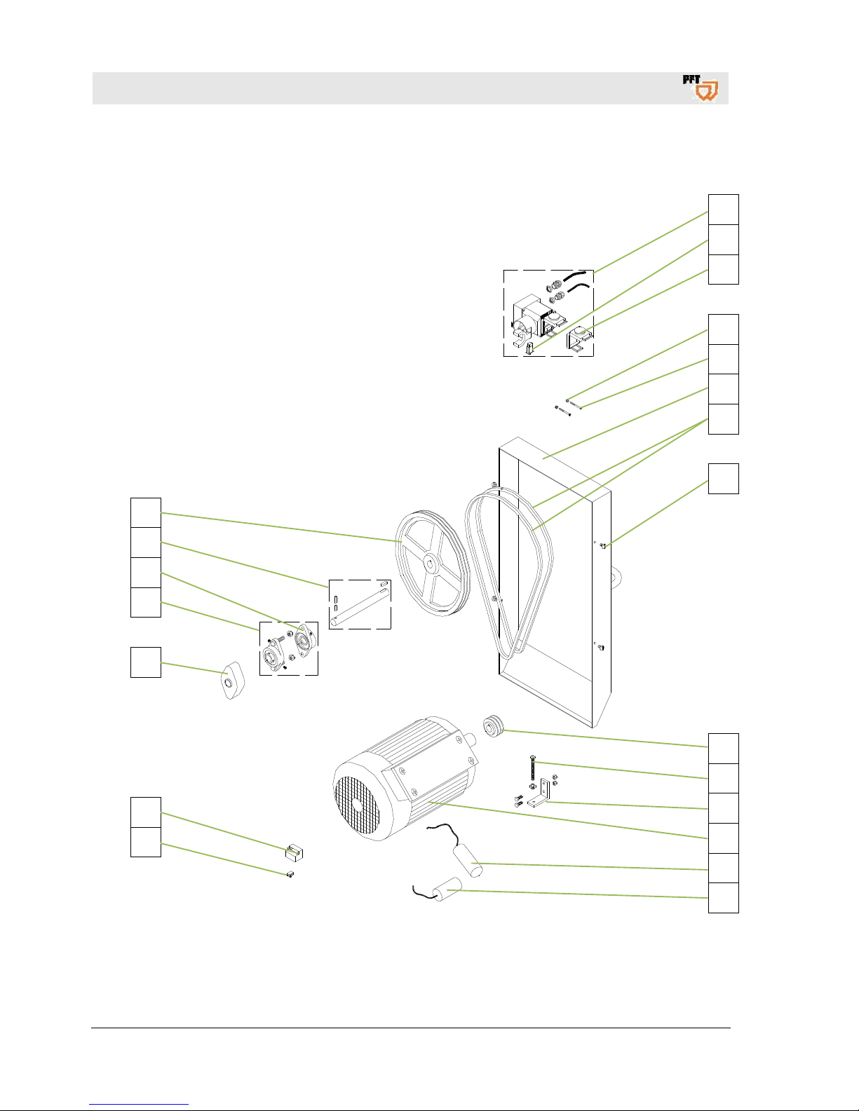
41.2 Gear motor
1
2
3
4
5
6
7
8
9
10
11
12
13
14
21
20
19
18
17
16
15
Page 45

PFT continuous mixer HM 2002 Overview - Operation - Spare parts lists
ET drawing / ET list of HM 2002
2017-03-14
45
ITEM Qty Article no. Article description
1
1 00 00 21 28
On/Off switch of HM 22/2002, 230 V 50 Hz complete with connection cable
and thermal protection 14 A
2
1 20 45 69 42 Thermo switch 10-12 A 230 V 50 Hz
3
1 00 05 44 88
Emergency stop button cover (yellow/red complete with screws) for On-Off
switch of HM 22/2002 230 V 1Ph. (art. no. 00002128)
4
2 20 20 66 02 Safety nut M5, galvanised
5
2 20 20 64 06 Cylinder head screw M5 x 50, galvanised
6
1 20 54 63 00 Cover hood of HM 2000/2002 RAL 2004
7
2 20 54 66 00 V-belt
8
4 20 20 78 11 Flat head screw M8 x 12, galvanised
9
1 20 54 65 00 V-belt pulley diameter 63 mm
10
1 20 20 78 03 Hex. screw M8 x 80 galvanised
11
1 20 54 62 10 Motor fixing angle of HM 2002 RAL 2004
12
1 20 14 19 00 Motor 2.2 KW 230 V 50 Hz 1 Phase
1 00 59 33 73 Motor 2.2 kW 120 V 60 Hz 1 Phase
1 On request Motor 2.2 KW 230 V 60 Hz 1 Phase
13
1 On request Capacitor 130 mF D=46 x 84 (Motor 2.2 KW 230 V 50 Hz 1 Phase)
14
1 00 02 12 00 Capacitor 50 myF D=45 x 116 (Motor 2.2 KW 230 V 50 Hz 1 Phase)
15
1 20 44 81 00 Klixon relay type 2CR4-273 (motor 2.2 KW 230 V 50 Hz 1 Phase)
16
1 20 44 80 00 Resistance 0.68 OHM, 12.5 W (motor 2.2 KW 230 V 50 Hz 1 Phase)
17
1 20 54 77 00 Protective cap for HM 2000/2002
18
1 20 54 67 00 Flange bearing unit complete with pivot ball bearing
19
1 00 03 62 43 Y-flange bearing, type FYTB 25TF
20
1 20 54 74 01 Drive shaft complete with clamping pins and feather keys 245 mm
21
1 20 54 64 00 V-belt pulley diameter 355 mm
Page 46
PFT continuous mixer HM 2002 Overview - Operation - Spare parts lists
ET drawing / ET list of HM 2002
46
2017-03-14
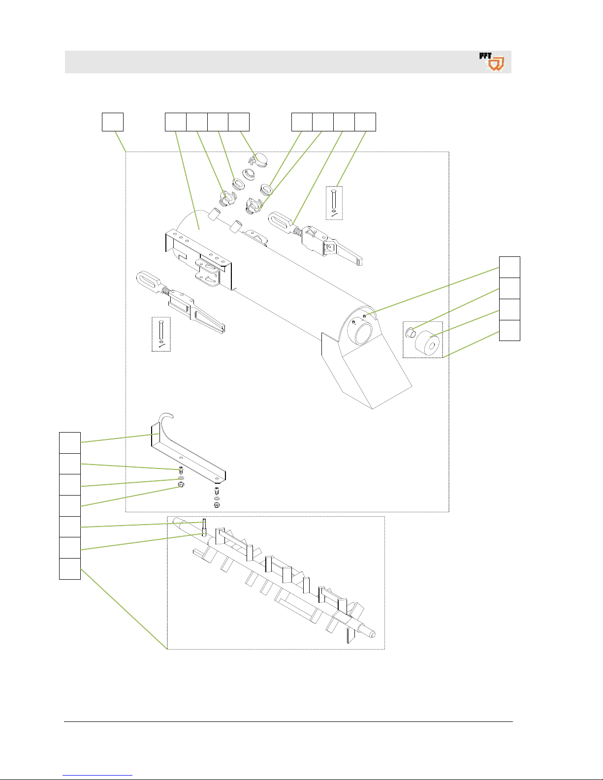
41.3 Mixing tube HM complete, art.no. 00002116
1 2 3 4 5 4 3 6 7
8
9
10
11
18
17
16
15
14
13
12
Page 47

PFT continuous mixer HM 2002 Overview - Operation - Spare parts lists
ET drawing / ET list of HM 2002
2017-03-14
47
ITEM Qty Article no. Article description
1
1 00 00 21 16 Mixing tube HM 22/24 complete
2
1 00 00 21 17 Mixing tube HM 22/24
3
2 20 20 09 00 Geka coupling 1/2” external thread
4
3 20 20 17 00 Gasket Geka coupling (pack.unit=50 pieces)
5
1 20 20 16 50 Geka coupling blind cover
6
2 20 10 08 01 Quick closure with locking device
7
2 20 20 85 22 Splint bolt with washer und splint, galvanised
8 2 20 20 99 92 Threaded pin with hexagon socket M6 x 6, galvanised
9
1 20 02 60 01 Plain bearing flange sleeve
10
1 20 02 60 02 Bearing bush thermoplast D60 x 40
11
1 20 54 82 10 End bearing HM 2/2000/2002 with bearing bush
12
1 00 01 99 67 Mixing shaft HM 2/22/24/2002 with reamer
13
1 20 54 76 00 Clamping pin 10 x 40
14
1 20 54 76 03 Clamping pin 6 x 40
15
2 20 20 72 00 Safety nut M8 galvanised
16
2 20 20 93 13 Washer B 8.4, galvanised
17
2 00 00 86 14 Safety screw, fillister head M 8x16 A2
18
1 00 00 71 52 Safety hooks for CEE plug
Page 48
PFT continuous mixer HM 2002 Overview - Operation - Spare parts lists
ET drawing / ET list of HM 2002
48
2017-03-14
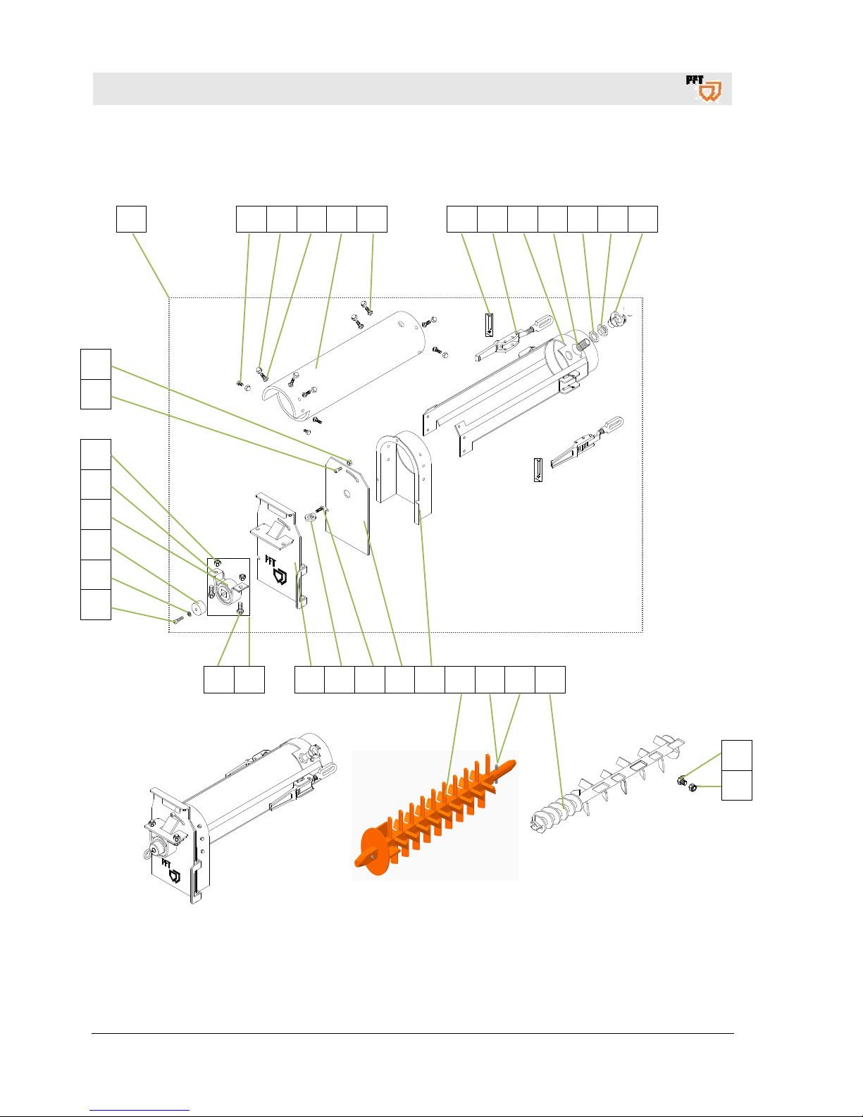
41.4 Mixing tube HM rubber, art.no. 00012594
1 2 3 4 5 6 7 8 9 10 11 12 13
33
34
32
31
30
29
28
27
26
25
24 23 22 21 20 19 18 17 16 15 14
Page 49

PFT continuous mixer HM 2002 Overview - Operation - Spare parts lists
ET drawing / ET list of HM 2002
2017-03-14
49
ITEM Qty Article no. Article description
1
1 00 01 25 94 Mixing tube HM 2 with rubber mixing section and rigid mortar outlet flange
2
2 20 20 87 01 Hexagon screw M8 x 16 (VPE 10)
3
10 20 20 66 03 Safety capped nut M8, galvanised
4
4 20 20 63 22 Saucer-head screw M8 x 20, galvanised
5
1 00 01 25 93 Rubber mixing tube HM 104/204 620 mm, notched out
6
4 20 20 63 23 Saucer-head screw M8 x 25, galvanised
7
2 20 20 85 22 Splint bolt with washer und splint, galvanised
8
2 20 10 08 01 Quick release fastener with locking device M14
9
1 00 01 25 91 Flange of rubber mixing tube HM 2 for rigid mortar outlet
10
1 00 00 22 29 Water inlet for rubber mixing tube HM 2
11
1 20 20 93 15 Washer
12
1 00 00 28 11 Tube nut G 1/2"
13
1 20 20 13 00 Geka coupling 1/2" internal thread
14
1 00 00 25 69 Dosing shaft HM 22/24 35l at 280 rpm
15
1 20 54 76 06 Clamping pin 10 x 50
16
1 20 54 76 05 Clamping pin 6 x 50
17
1 00 43 11 98 Sprocket mixing shaft HM 2002 (4 levels) RAL2004
18
1 00 01 25 92 Mortar outlet flange of rubber mixing tube HM 2, rigid
19
1 00 01 94 21 Rubber star plate for mortar outlet flange
20
1 20 20 78 00 Hex. screw M 8 x 30 galvanised
21
1 20 20 79 50 Ring nut M8, galvanised
22
1 00 01 94 20 Star plate for mortar outlet flange
23
1 20 54 55 01 Square external bearing with bearing housing
24
2 20 20 99 63 Hexagon screws M12 x 25 galvanised (pack.unit 10)
25
1 00 02 04 09 Cylinder screw with hexagon socket M8 x 25, galvanised
26
1 20 20 93 14 Serrated washer A 8.4, galvanised
27
1 20 54 54 09 Locking washer HM
28
1 20 54 55 06 Square external bearing
29
1 00 04 13 96 Bearing housing
30
2 20 20 89 00 Safety nut M12 galvanised
31
1 20 20 97 11 Cylinder screw with hexagon socket M8 x 20 galvanised
32
1 20 20 64 00 Hex-nut M 8, galvanised
33
1
20 20 87 02 Hexagonal screw M8 x 10, galvanised
34
1
20 20 72 00 Safety nut M8 galvanised
Page 50
PFT continuous mixer HM 2002 Overview - Operation - Spare parts lists
ET drawing / ET list of HM 2002
50
2017-03-14
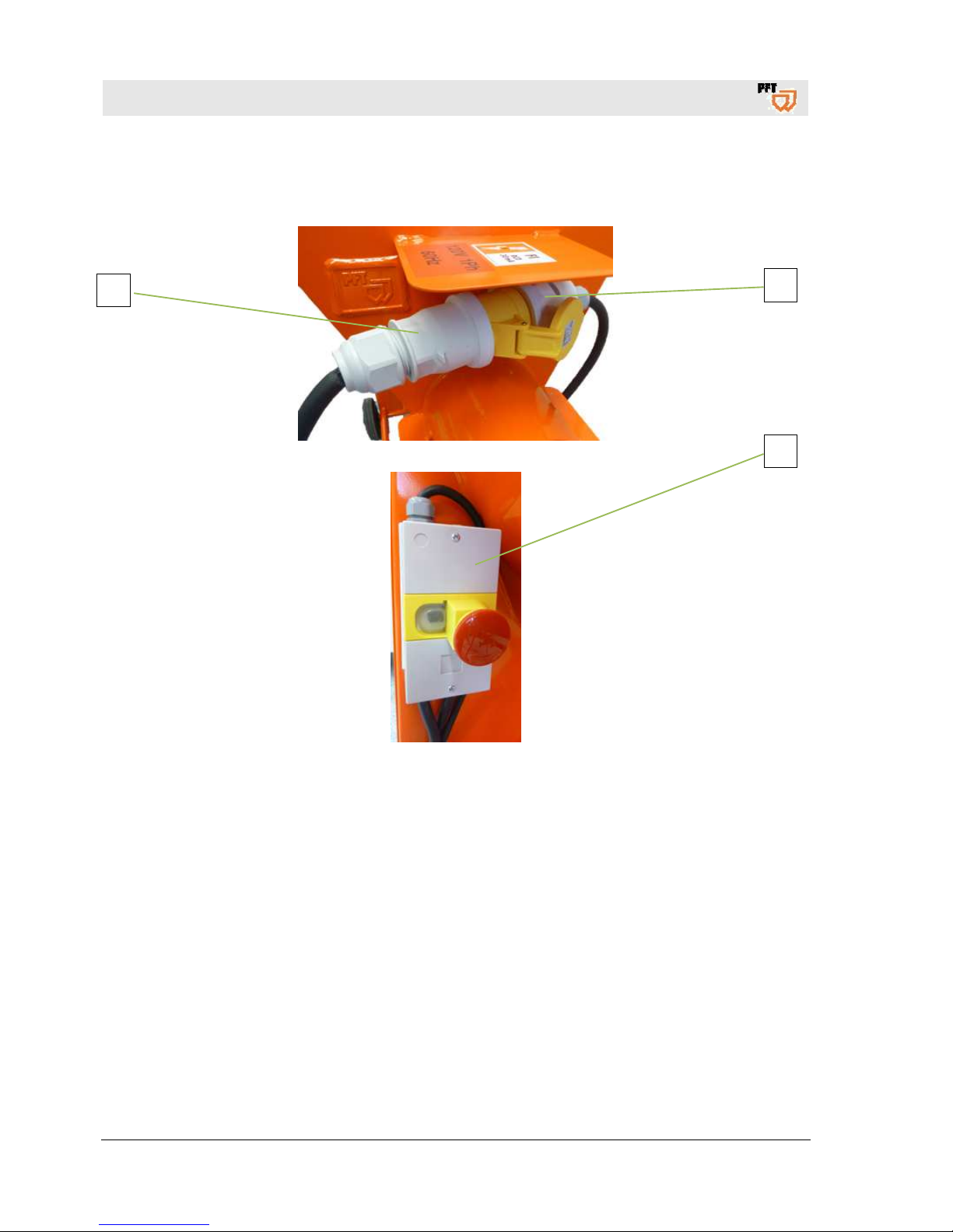
41.5 Cable set 120 V 60 Hz art.no. 00593375
1
2
3
Page 51

PFT continuous mixer HM 2002 Overview - Operation - Spare parts lists
ET drawing / ET list of HM 2002
2017-03-14
51
ITEM Qty Article no. Article description
1
1 On request CEE connection plug 3 x 16 A, yellow
2
1 On request Motor protection switch
3
1 On request CEE coupling 3 x 16A, yellow
Page 52
PFT continuous mixer HM 2002 Overview - Operation - Spare parts lists
ET drawing / ET list of HM 2002
52
2017-03-14
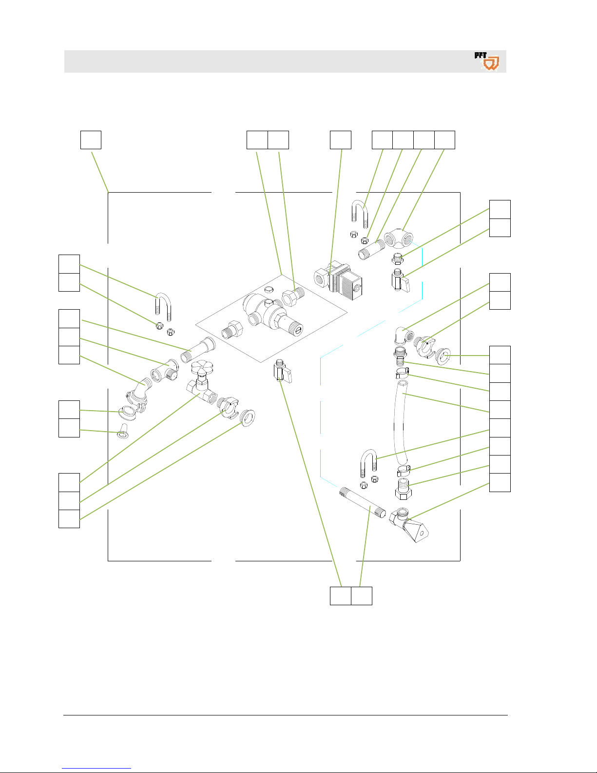
41.6 Water fitting HM 2002
1 2 3 4 5 6 7 8
10 19
9
10
11
12
13
14
15
16
5
15
17
18
5
6
24
23
22
13
21
20
12
13
Page 53

PFT continuous mixer HM 2002 Overview - Operation - Spare parts lists
ET drawing / ET list of HM 2002
2017-03-14
53
ITEM Qty Article no. Article description
1
1 00 00 27 75 Water fitting HM 2002 50 Hz
1 00 59 34 64 Water fitting HM 2002 60 Hz
2
1 00 00 15 58 Pressure reducer D06F 1/2"
3 1 20 20 31 07 Flat nipple 1/2" external thread with union nut 3/4” internal thread
4 1 20 15 03 01 Solenoid valve 1/2", 230 V, 50 Hz Type 6213 A (water fitting 00002775)
00 59 33 77 Solenoid valve 1/2", 120 V, 60 Hz Type 6213 A (water fitting 00593464)
5
3 20 20 99 85 Round steel bow M8 x 3/4" x 43, galvanised
6
6 20 20 72 00 Safety nut M8 galvanised
7
1 20 20 34 01 Double nipple 1/2" x 60, galvanised
8
1 20 20 46 20 Angular distributor 3 x 1/2" internal thread, galvanised
9
1 20 20 52 00 Reducing nipple 1/2" external thread 1/4" internal thread, galvanised
10
2 20 21 53 03 Ball valve 1/4" external thread with sleeve 10mm
11
1 20 20 36 11 Angle 1/2" internal thread, galvanised
12
2 20 20 09 00 Geka coupling 1/2" external thread
13
4 20 20 17 00 Gasket of Geka coupling (PACKING UNIT = PCS 50)
14
1 20 19 04 10 Hose coupling 1/2" external thread sleeve 1/2"
15
2 00 05 91 96 Hose clip 19-21
16
1 20 21 35 01 Water hose/air hose 1/2" x 700mm
17
1 20 20 37 80 Hose fitting 1/2" conical with union nut 3/4"internal thread
18
1 20 15 77 00 Needle valve 1/2"
19
1 20 20 34 11 Double nipple 1/2" x 120, galvanised
20
1 20 21 52 00 Shut-off valve 1/2” without drain
21
1 20 15 20 00 Strainer screen for Geka coupling (PACKING UNIT = 10 PCS)
22
1 00 14 75 67 Geka coupling nipple 1/2"external thread - 45° inclination
23
1 20 20 42 00
T-piece 1/2" internal thread 1/2" external thread 1/2" internal thread,
24
1 20 20 34 22 Extension 1/2" x 80, galvanised
Page 54
PFT continuous mixer HM 2002 Overview - Operation - Spare parts lists
ET drawing / ET list of HM 2002
54
2017-03-14
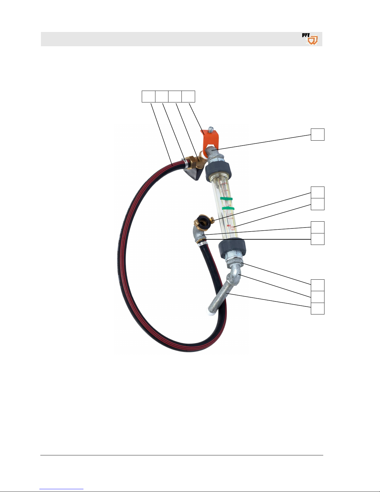
41.7 Retrofit kit for water flow meter 100 - 1,000 l/h for HM 2002
1 2 3 4
5
6
7
8
9
10
11
12
Page 55

PFT continuous mixer HM 2002 Overview - Operation - Spare parts lists
ET drawing / ET list of HM 2002
2017-03-14
55
ITEM Qty Article no. Article description
1
1 20213502 Water hose/air hose 1/2" x 960 mm
2
2 00059196 Hose clip 19-21
3
1 20157700 Needle valve 1/2” type 6701
4 1 00020117 Bracket of flow meter HM 2002
5 1 20203511 Bend 1/2" 90 ° external thread-external thread, galvanised
6
1 20200900 Geka coupling 1/2" external thread (PACKING UNIT = 10 PCS)
7
1 00002213 Water flow meter 100-1000 l/h 250 mm
8
1 20203611 Angle 1/2" internal thread, galvanised
9
1 20190410 Hose coupling 1/2" external thread sleeve 1/2"
10
1 20205400 Reduction nipple 1”external thread 1/2" internal thread
11
1 20203610 Angle 1/2" internal thread-external thread, galvanised
12
1 20203414 Double nipple 1/2" x 180, galvanised
Page 56

PFT continuous mixer HM 2002 Overview - Operation - Spare parts lists
Index
56
2017-03-14
42 Index
A
Accessories ........................................................ 15
Action in case of power cut ................................ 28
Actions after completed maintenance ............... 40
Advantages at a glance ..................................... 17
Apply mortar ....................................................... 27
B
Brief description ................................................. 16
C
Cable set 120 V 60 Hz art.no. 00593375 .......... 50
Changing the V-belt ........................................... 39
Check consistency of material ........................... 26
Clean HM 2002 .................................................. 33
Clean the material container .............................. 34
Clean the strainer screen ................................... 23
Cleaning ............................................................. 31
Cleaning the dosing shaft .................................. 35
Cleaning the mixing shaft .................................. 33
Cleaning the mixing tube ................................... 34
Connect the water hose to the mixing tube ....... 25
Connecting the power supply ............................ 22
Connecting the water hose ................................ 23
Connecting the water supply ............................. 23
Connection of water from water tank ................. 24
Connection value of water ....................................8
Connections ....................................................... 13
CONTINUOUS MIXER PFT HM 2002 ............... 16
D
Danger to life from rotating parts ....................... 22
Dimension sheet HM 2002 ................................ 10
Disassembly ....................................................... 41
Disassembly ....................................................... 40
Disconnect power supply. .................................. 28
Disposal ............................................................. 41
Division .................................................................7
Dosing shaft ....................................................... 13
E
EC Declaration of Conformity .............................. 5
Emergency-stop switch ...................................... 28
Empty mixing tube ............................................. 32
End of work / clean machine .............................. 32
ET ....................................................................... 42
Examination ......................................................... 6
Examination by machine operator ....................... 6
F
Faults ................................................................. 29
Feeding material to the machine ........................ 25
Fields of application ........................................... 16
G
Gear motor ......................................................... 44
General information ......................................... 6, 7
Grille cover ......................................................... 21
H
Hazardous dusts ................................................ 25
I
Index .................................................................. 56
Interruption of work ............................................ 27
K
Keep the manual for future reference .................. 7
L
Lubrication .......................................................... 39
M
Machine preparation .......................................... 21
Maintenance ....................................................... 36
Maintenance plan ............................................... 38
Maintenance work .............................................. 38
Material container with frame ............................. 42
Material: ............................................................. 16
Measures in case of risk of frost ........................ 36
Measures to be taken in case of water outage .. 31
Mixing shaft ........................................................ 13
Mixing tube HM complete, art.no. 00002116 ..... 46
Page 57

PFT continuous mixer HM 2002 Overview - Operation - Spare parts lists
Index
2017-03-14
57
Mixing tube HM rubber, art.no. 00012594 .......... 48
Monitoring the machine ...................................... 26
N
Name plate ......................................................... 10
O
Operating conditions ............................................. 9
Operating manual ................................................. 6
Operation ............................................................ 20
Overview of HM 2002 ......................................... 11
P
Packaging ........................................................... 18
Packaging ........................................................... 20
Periodic inspection ............................................... 6
Personal protective equipment
installation ....................................................... 29
operation ......................................................... 20
Personnel
disassembly .................................................... 40
Initial start-up .................................................. 30
installation ....................................................... 30
Power connection 120 V ..................................... 32
Power connection 120 V 60 Hz .......................... 22
Power connection 120 V 60 Hz .......................... 14
Power connection 230 V ..................................... 32
Power connection 230 V 50 Hz .......................... 13
Power connection 230 V 50 Hz .......................... 22
Power connection 230 V 60 Hz .......................... 22
Power connection 230 V 60 Hz .......................... 14
Power connection values 120 V 60 Hz ................. 9
Power connection values 230 V 50 Hz ................. 8
Power connection values 230 V 60 Hz ................. 8
Pre-setting the water flow rate ............................ 24
Putting the machine into operation ..................... 26
Q
Quality Control sticker ........................................ 10
R
Reaction in the event of faults ............................ 29
Remove connection cable .................................. 37
Retrofit kit for water flow meter 100 - 1,000 l/h for
HM 2002 ................................................... 12, 54
Risk of frost .........................................................35
Rubber mixing tube art.no. 00012594 ................13
S
Safety ........................................................... 29, 36
Safety ..................................................................20
Safety ..................................................................40
Safety instructions for transport ..........................18
Safety rules .........................................................17
Secure against restarting ....................................33
Secure against restarting ....................................31
Setting the mixing shaft ......................................35
Setting water factor .............................................24
Sound power level ................................................ 9
Stopping in case of an emergency .....................28
Stopping in case of an emergency .....................28
Storage ...............................................................18
Strainer screen ...................................................38
Strainer screen in pressure reducer ...................38
Structure of HM 2002 ..........................................11
Switching off HM 2002 120 V .............................27
Switching off HM 2002 230 V .............................27
Switching off the machine ...................................27
Switching on the machine at 120 V ....................26
Switching on the machine at 230 V ....................26
T
Table of faults .....................................................30
Technical data ...................................................... 7
Transport.............................................................18
Transport in individual parts................................19
Transport inspection ...........................................19
Transport of machine in operation ......................19
V
Vibrations .............................................................. 9
W
Water fitting .........................................................12
Water fitting HM 2002 .........................................52
Work on troubleshooting .....................................29
Page 58

PFT continuous mixer HM 2002 Overview - Operation - Spare parts lists
58
2017-03-14
Page 59

PFT continuous mixer HM 2002 Overview - Operation - Spare parts lists
2017-03-14
59
Page 60

PFT continuous mixer HM 2002 Overview - Operation - Spare parts lists
60
2017-03-14
THE FLOW OF PRODUCTIVITY
Knauf PFT GmbH & Co. KG
P.O. Box no. 60 97343 Iphofen
Einersheimer Straße 53 97346 Iphofen
Germany
Phone +49 9323 31-760
Fax +49 9323 31-770
Technical hotline +49 9323 31-1818
www.pft.eu
 Loading...