

Page 1
74
Table of contents
2019-01-15
Operating manual
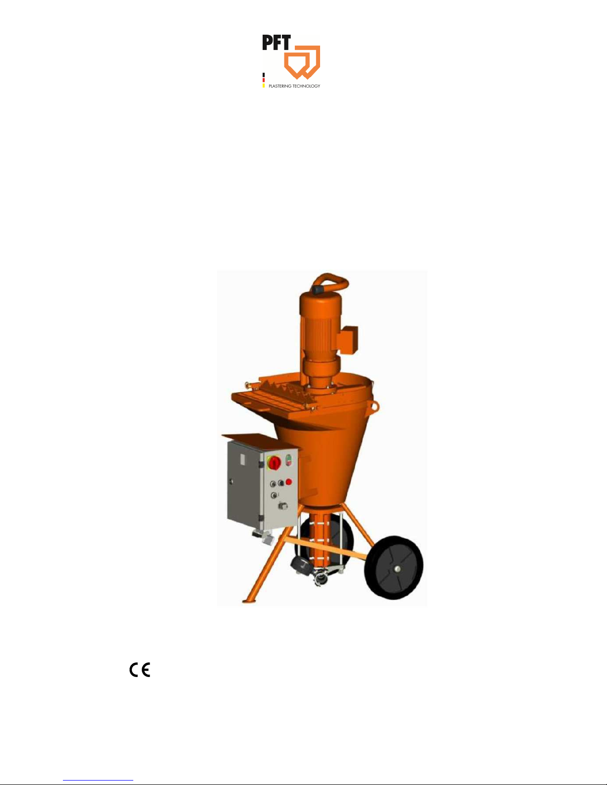
Mixing pump BOLERO 230V, 2,2kW
Part 2 EC Declaration of Conformity
Overview - Operation - Spare parts lists
Article number of the operating manual: 00 25 58 50
Article number of the parts list-machine: 00 24 53 37
Read the operating manual prior to starting any works!
Page 2

2
2019-01-15
© Knauf PFT GmbH & Co.KG
Postfach 60 97343 Iphofen
Einersheimer Straße 53 97346 Iphofen
Germany
Phone: +49 (0) 93 23/31-760
Fax: +49 (0) 0 93 23/31-770
Technical hotline +49 9323 31-1818
Page 3

Mixing pump BOLERO 230V, 2,2kW Overview - Operation - Spare parts lists
Table of contents
2019-01-15
3
1 EC Declaration of Conformity ..................... 5
2 Examination .................................................. 6
2.1 Examination by machine operator ....... 6
2.2 Periodic inspection .............................. 6
3 General information ..................................... 7
3.1 Information regarding the operating
manual ................................................. 7
3.2 Keep the manual for future
reference .............................................. 7
3.3 Division ................................................ 7
4 Spare parts lists ........................................... 8
5 Accessories .................................................. 8
6 Technical data .............................................. 9
6.2 Power connection ................................ 9
6.3 Operating conditions .......................... 10
6.4 Power values ..................................... 10
7 Sound power level ..................................... 10
8 Vibrations ................................................... 10
9 Dimension sheet ........................................ 11
10 Name plate .................................................. 11
11 Quality Control sticker .............................. 11
12 Assembly .................................................... 12
12.1 Overview ............................................ 12
13 Description of assemblies ........................ 13
13.1 Gear motor with protective grille ........ 13
13.2 Agitator .............................................. 13
13.3 Material container with control
cabinet ............................................... 13
13.4 Control cabinet .................................. 14
14 Operating modes ....................................... 14
14.1 Selector switch pump motor .............. 14
14.2 Selector switch mixing function in
conveying breaks ............................... 14
15 Connection .................................................. 15
15.1 Connection mortar hose ..................... 15
16 Recommended accessories ...................... 15
17 Accessories ................................................ 15
17.1 Remote control cable ......................... 15
18 Functional description ............................... 16
19 Material ........................................................ 16
19.1 Flowability / Flow characteristics ........ 16
20 Mortar pressure gauge .............................. 16
21 Safety rules ................................................. 16
22 Transport, packing and storage................ 17
22.1 Safety instructions for transport ......... 17
22.2 Closing the motor tilt flange................ 17
22.3 Close quick closure during transport .. 18
22.4 Transport checklist ............................. 18
22.5 Transport in individual parts ............... 18
22.6 Transport by crane ............................. 19
22.7 Transportation of operational
machines ............................................ 19
23 Packaging .................................................... 20
24 Operation ..................................................... 20
24.1 Safety ................................................. 20
25 Preparation .................................................. 21
25.1 Connection of power supply ............... 22
25.2 Motor connecting cable for pump
motor .................................................. 22
26 Fill water into the material container ........ 22
26.1 Trial run .............................................. 23
27 Mortar pressure gauge .............................. 23
28 Mortar hoses ............................................... 24
28.1 Prepare mortar hoses ........................ 24
28.2 Connect mortar hose .......................... 24
Page 4

Mixing pump BOLERO 230V, 2,2kW Overview - Operation - Spare parts lists
Table of contents
4
2019-01-15
28.3 Connect Zargomat and gluing gun .... 25
29 Putting the machine into operation .......... 25
29.1 Start off machine ................................ 25
29.2 Fill machine with factory prepared
dry material ........................................ 25
29.3 Hazardous dusts ................................ 26
29.4 Connect remote control ..................... 26
30 Switching on ............................................... 27
30.1 Apply material .................................... 27
30.2 Switching off the machine .................. 27
30.3 Switch machine on again ................... 28
30.4 Re-tighten pump ................................ 28
31 Interruption of work ................................... 28
32 Stopping in case of emergency ................ 29
32.1 Emergency OFF switch ..................... 29
33 Measures to be taken in the event of a
power failure ............................................... 29
33.1 Turning the main switch to position
“0” ....................................................... 29
33.2 Discharging mortar pressure ............. 30
33.3 Switching on the machine again
after a power failure ........................... 30
34 Work on troubleshooting .......................... 31
34.1 Reaction in the event of faults ........... 31
34.2 Fault displays ..................................... 31
34.3 Faults ................................................. 31
34.4 Safety ................................................. 32
34.5 Table of faults .................................... 32
35 Conveying stationary / clogging .............. 33
35.1 Signs for clogging .............................. 33
35.2 Causes for blockages: ....................... 34
35.3 Earlier damage to the mortar hose .... 34
35.4 Removal of clogging in hoses ........... 34
35.5 Risk of injury to due overpressure ..... 35
35.6 Cleaning the pump ............................ 35
36 End of shift / Cleaning ............................... 36
36.1 Switching off the energy supplies ...... 36
36.2 Cleaning BOLERO ............................ 36
36.3 Clean mortar hose ............................. 37
36.4 Clean Zargomat and gluing gun ........ 38
36.5 Clean he material container .............. 38
36.6 Switching on the machine ................. 38
36.7 Removing the connection cable ........ 38
36.8 Open protective grille......................... 39
36.9 Clean material container ................... 39
37 Risk of frost ................................................ 40
38 Maintenance ............................................... 40
38.1 Safety ................................................ 40
38.2 Cleaning ............................................ 41
38.3 Maintenance plan .............................. 42
38.4 Gear motor ........................................ 42
38.5 Remove agitator ................................ 43
38.6 Lubricate freewheel ........................... 43
38.7 Measures after effected
maintenance ...................................... 43
39 Disassembly ............................................... 44
39.1 Safety ................................................ 44
39.2 Disassembly ...................................... 45
39.3 Disposal ............................................. 45
40 Spare parts list pump shaft ...................... 45
41 Index............................................................ 46
Page 5

Mixing pump BOLERO 230V, 2,2kW Overview - Operation - Spare parts lists
EC Declaration of Conformity
2019-01-15
5
1 EC Declaration of Conformity
Company:
Knauf PFT GmbH & Co. KG
Einersheimer Straße 53
97346 Iphofen
Germany
declare under our sole responsibility that the product:
Machine type: BOLERO
Type of device: Mixing pump
Serial number:
Guaranteed sound power level: 78 dB
is in conformity with the following CE directives:
• Outdoor directive (2000/14/EC),
• Machine directive (2006/42/EC),
• Electromagnetic Compatibility Directive (2014/30/EG).
Operative Conformity Assessment according to Outdoor Directive 2000/14/EC:
Internal production control as per article 14 paragraph 2 in connection with annex V.
This declaration relates exclusively to the machinery in the state in which it was placed on the market, and
excludes components which are added and/or operations carried out subsequently by the final user. The
declaration ceases to be valid, if the product is modified without authorisation.
Person authorised to compile the relevant technical documentation:
Dipl.-Wirtsch.-Ing. (FH) Michael Duelli, Einersheimer Straße 53, 97346 Iphofen.
The technical documentation is available from:
Knauf PFT GmbH & Co.KG, Technische Abteilung, Einersheimer Straße 53, 97346 Iphofen.
Iphofen, Dr. York Falkenberg
Managing Director
Place, Date of issue Name and signature Details about the signatory
Page 6

Mixing pump BOLERO 230V, 2,2kW Overview - Operation - Spare parts lists
Examination
6
2019-01-15
2 Examination
2.1 Examination by machine operator
Prior to each shift, the machine operator has to examine the
effectiveness of the control and safety devices as well as the
proper fitting of the protection devices.
The safe working condition of construction machinery has to be
checked by the machine operator during operation.
If the safety devices show any defects or if any other defects are
detected that compromise a safe operation, the supervisor has to
be informed immediately.
In case of defects that cause harm to persons, the operation of the
construction machine has to be stopped to eliminate the defects.
2.2 Periodic inspection
Construction machinery has to be inspected for their safe working
condition in accordance with the operating conditions and the
operational requirements as needed, however at least once a year
by an expert.
Pressure vessels have to undergo the prescribed expert
inspections.
The inspection results have to be documented and kept at least
until the next inspection.
Page 7

Mixing pump BOLERO 230V, 2,2kW Overview - Operation - Spare parts lists
General information
2019-01-15
7
3 General information
3.1 Information regarding the operating manual
This operating manual gives important information on handling the
device. A prerequisite for safe working is the observance of all
stated safety guidelines and instructions.
Furthermore the local accident prevention guidelines and general
safety instructions for the application area of the device are to be
adhered to.
Read the operating manual thoroughly before starting any work! It
is a part of the product and has to be kept near the tool and easily
accessible to the staff at all times.
If the tool is given to third parties, also include the operating
manual.
The figures in this manual are for presentation purposes of facts
not necessarily to scale and may slightly differ from the actual
model of the device.
3.2 Keep the manual for future reference
The operating manual has to be available during the whole service
life of the product.
3.3 Division
The operating manual is divided into 2 books:
Part 1 Safety
General safety instructions mixing pumps/feed pumps
Article number: 00 17 27 09
Part 2 Overview, operation, service and spare parts lists (this
volume).
For safe operation of the device both parts have to be read and
observed. Together they form one operating manual.
Page 8
Mixing pump BOLERO 230V, 2,2kW Overview - Operation - Spare parts lists
Spare parts lists
8
2019-01-15
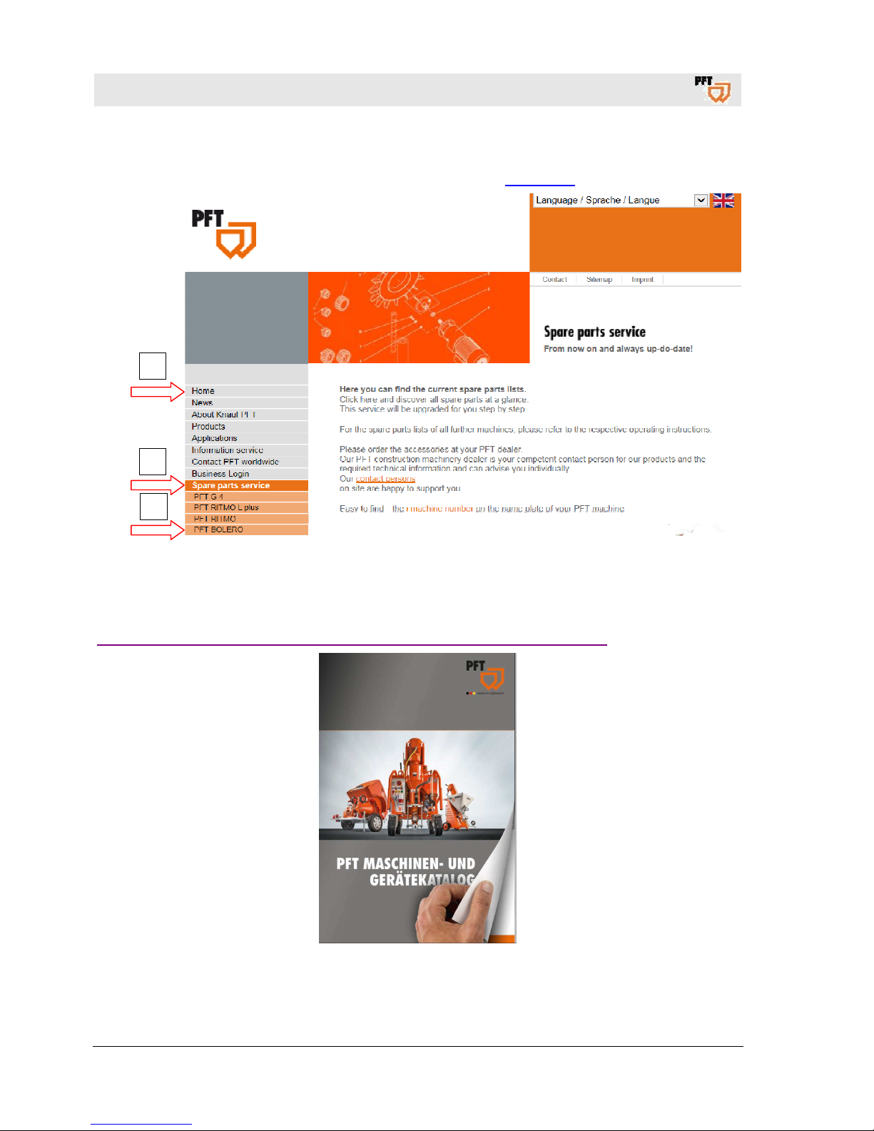
4 Spare parts lists
Spare parts lists for the machine can be found on the internet at www.pft.net.
5 Accessories
For recommended accessories/equipment, see PFT Machine and Equipment Catalogue or:
http://www.pft.eu/www/en/produkte/produktprogramm/mischpumpen/mischpumpe.php
1
2
3
Page 9

Mixing pump BOLERO 230V, 2,2kW Overview - Operation - Spare parts lists
Technical data
2019-01-15
9
6 Technical data
6.1.1 General information
Description Value Unit
Weight 112 kg
Length approx. 800 mm
Width approx. 696 mm
Height approx. 1480 mm
Filling height 950 mm
Individual weights
Description Value Unit
Pump motor with protective grille 42 kg
Undercarriage with pump and
control cabinet
64 kg
Agitator 6 kg
Hopper dimensions
Description Value Unit
Filling height 950 mm
Hopper content 68 l
6.2 Power connection
Electrical details
Description Value Unit
Voltage, AC 50 Hz 230 V
Power consumption, max. 8,7 A
Power input, max. 2,2 kW
Fuse protection min. 3 x 16 A
Drive pump motor 2,2 kW
Speed pump motor approx. 0 - 170 rpm
Power input pump motor, max.
8,7 A
Page 10

Mixing pump BOLERO 230V, 2,2kW Overview - Operation - Spare parts lists
Sound power level
10
2019-01-15
6.3 Operating conditions
Environment
Description Value Unit
Temperature range 2-45 °C
Relative humidity, max. 80 %
Duration
Description Value Unit
Max. operating time at a stretch 8 hours
6.4 Power values
Pump capacity
D4-2 standard equipment
Description Value Unit
Pump capacity, approx. 0 - 11 l/min.
Operating pressure, max. 20 bar
Grain size max. 4 mm
Feed range *, max. at 25 mm ∅
15 m
Feed range *, max. at 35 mm ∅
25 m
* reference value depending on conveying height, pump condition and version,
mortar quality, composition and consistency.
7 Sound power level
Guaranteed sound power level LWA 78dB (A)
8 Vibrations
Weighted effective value of acceleration to which the upper body parts are exposed <2.5 m/s²
Page 11
Mixing pump BOLERO 230V, 2,2kW Overview - Operation - Spare parts lists
Dimension sheet
2019-01-15
11
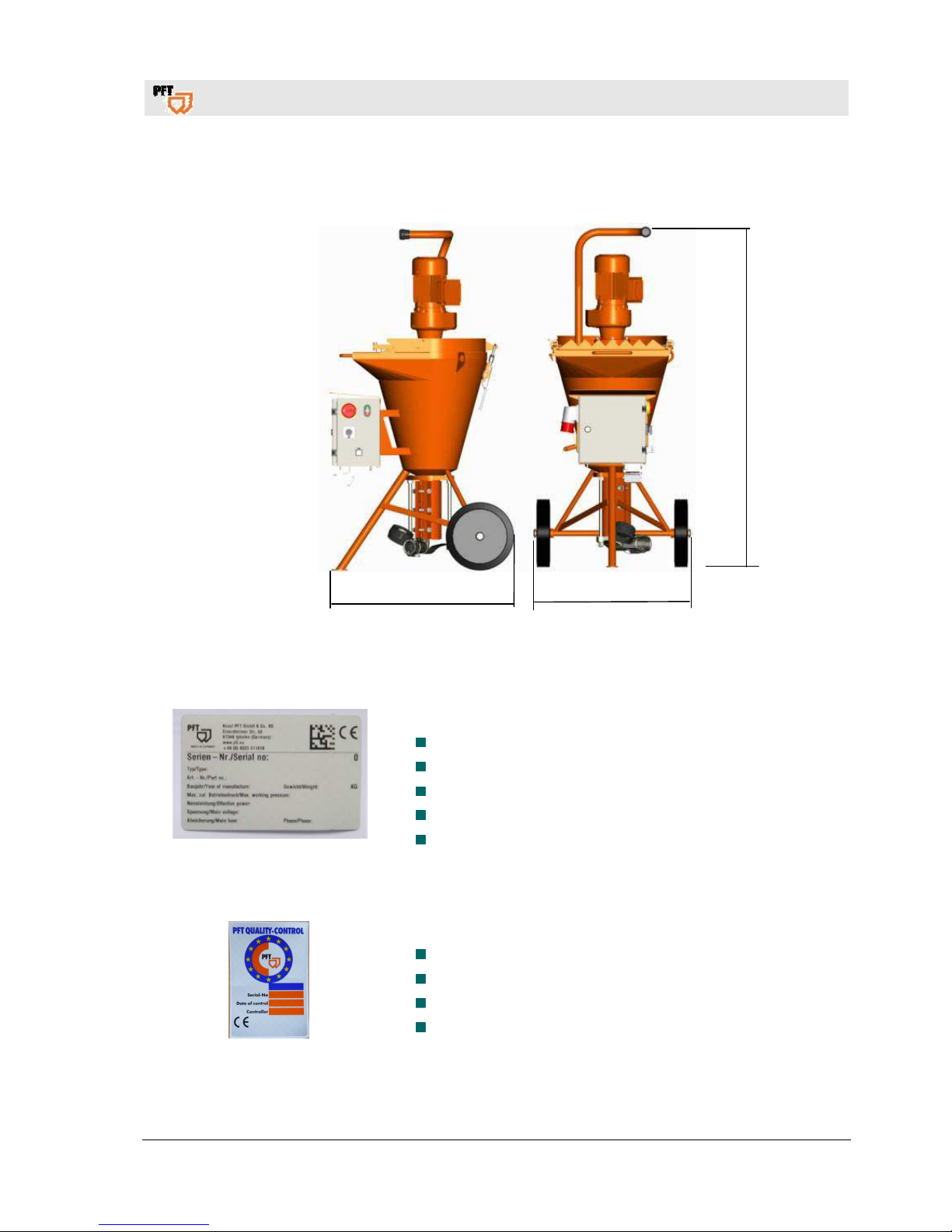
9 Dimension sheet
Fig. 1: Dimension sheet PFT BOLERO
10 Name plate
Fig.2: Name plate
The following details can be found on the name plate:
Manufacturer
Type
Year of manufacture
Machine number
Permissible operating pressure
11 Quality Control sticker
Fig.3: Quality Control sticker
The following details can be found on the Quality Control sticker:
CE confirmed as per EU directives
Serial number
Controller / signature
Date of control
696
800
Page 12
Mixing pump BOLERO 230V, 2,2kW Overview - Operation - Spare parts lists
Assembly
12
2019-01-15
12 Assembly
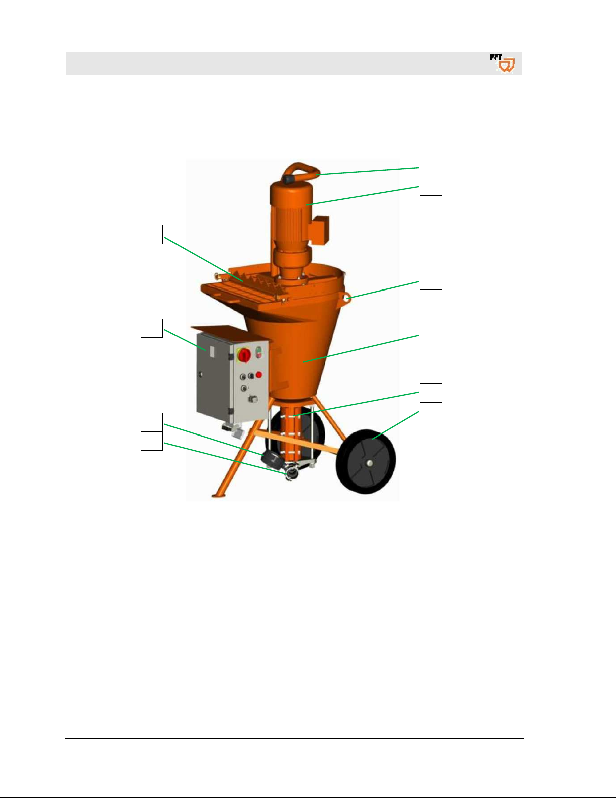
12.1 Overview
Fig. 4: Overview BOLERO
1 Motor protection handle
2 Gear motor
3 Crane eyelet
4 Material container
5 Pump unit
6 Plastic wheel
7 Connection mortar pressure hose
8 Mortar pressure gauge
9 Control cabinet
10 Protective grille with sack opener
1
2
3
4
5
6
10
9
8
7
Page 13
Mixing pump BOLERO 230V, 2,2kW Overview - Operation - Spare parts lists
Description of assemblies
2019-01-15
13
13 Description of assemblies
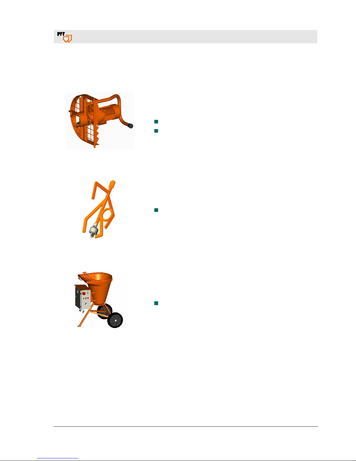
13.1 Gear motor with protective grille
Fig.5: Gear motor with protective grille
The mixing pump PFT Bolero consists of the following main
components:
Protective grille with motor flange and gear motor.
The gear motor with motor flange can be removed from the
material container for transport purposes.
13.2 Agitator
Fig.6: Agitator
Agitator BOLERO with freewheel and lubrication nipple.
13.3 Material container with control cabinet
Fig. 7: Material container with control
cabinet
Material container with control cabinet.
Page 14
Mixing pump BOLERO 230V, 2,2kW Overview - Operation - Spare parts lists
Operating modes
14
2019-01-15
13.4 Control cabinet
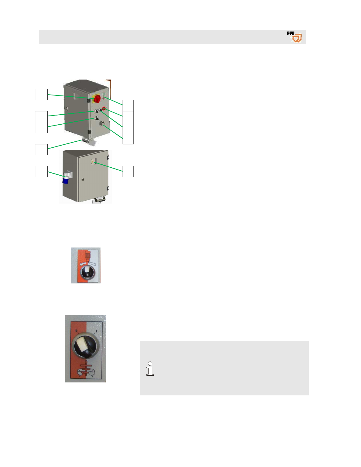
Fig. 8: Control cabinet
1. Operation button machine ON / OFF (control voltage).
2. Control lamp LED red, motor protection switch triggered.
3. Potentiometer for engine speed / material quantity.
4. Dummy plug / connection remote control.
5. Viewing window for frequency converter.
6. Main terminal 230V, 1phase, 16A.
7. Power connection 10 pin for pump motor.
8. Selector switch mixing backwards.
9. Selector switch operating mode "mixing OFF pumps".
10. Main switch is at the same time "EMERGENCY-OFF" switch.
14 Operating modes
14.1 Selector switch pump motor
Fig. 9: Selector switch
Selector switch pump motor:
Selector switch in middle position - agitator is switched off.
Selector switch in right position - pump.
Selector switch to left position - mix.
14.2 Selector switch mixing function in conveying breaks
Fig. 10: Selector switch
Selector switch mixing function:
Selector switch to "0" - mixing function is switched off.
Selector switch in position "1" - mixing function is switched on.
NOTE!
For special mortar, an additional mixer function can
be switched.
When the selector switch to position "1" on the
machine with conveyor breaks (off by remote control)
automatically in the mixing process. The material is
mixed continuously.
1
2
3
4
5
10
9
8
7
6
Page 15
Mixing pump BOLERO 230V, 2,2kW Overview - Operation - Spare parts lists
Connection
2019-01-15
15
15 Connection
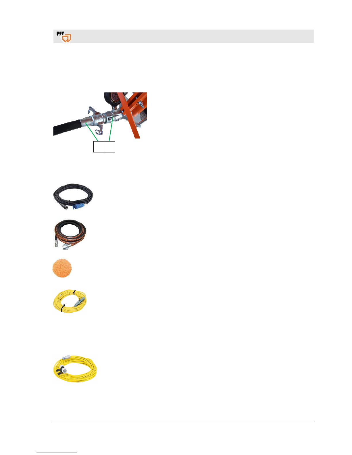
15.1 Connection mortar hose
1 2
Fig. 11: Connection mortar hose
1. Connection mortar hose (1) at the mortar pressure gauge (2).
16 Recommended accessories
Fig. 12: Power cable
Power cable 3 x 2,5 25m with Schuko-plug and coupling CEE 3 x
16A 6h blue
(article number 20423420)
Fig. 13: Mortar hose
RONDO mortar pressure hose 25mm 15m with hydraulically fitted
couplings
(article number 00021101)
Fig. 14: Sponge ball
RONDO sponge ball 30mm diameter solid (pack.unit 20)
(article number 20210500)
Fig. 15: Extension cable
Extension cable 25m for remote control with plug and coupling
(article number 20456931)
17 Accessories
17.1 Remote control cable
Fig. 16: Remote control cable
Remote control cable 25m complete with ON/OFF switch and
control lamp
(article number 20456929)
Page 16
Mixing pump BOLERO 230V, 2,2kW Overview - Operation - Spare parts lists
Functional description
16
2019-01-15
18 Functional description
The handy PFT BOLERO is a combined mixing, pumping and spraying machine. The new PFT BOLERO is
the perfect machine if material which is roughened up intermittently are to be processed.
In anticlockwise mode of the mixing shaft the material is mixed continuously. In clockwise mode the feed
pump is connected and pumps the ready-mixed material to the point of use.
19 Material
19.1 Flowability / Flow characteristics
NOTE!
The pump D4-2 can be used up to 20 bar operating pressure.
The possible conveying distance depends mainly on the flowability of the material.
If 20 bar operating pressure are exceeded the mortar hose length has to be reduced.
In order to avoid machine faults and increased wea
r of the pump motor, pump shaft and the
pump itself, only original PFT spare parts such as
PFT rotors
PFT stators
PFT agitator
PFT mortar hoses must be used.
These are compatible with each other and form a constructive unit with the machine.
Non-compliance does not only cause loss of guarantee, but also bad mortar quality is to be
expected.
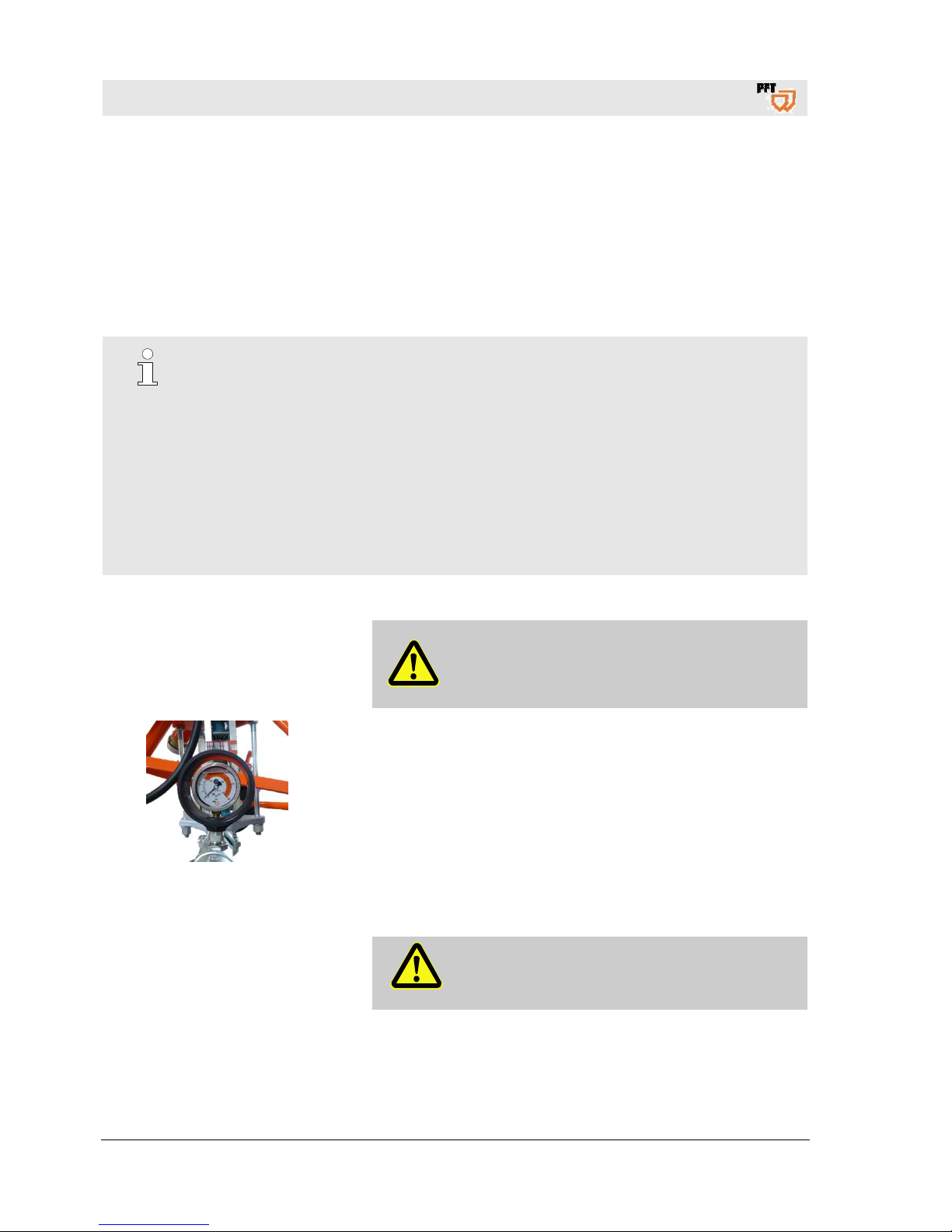
20 Mortar pressure gauge
Attention!
The use of a mortar pressure gauge is
recommended for safety-related reasons.
Fig. 17: Mortar pressure gauge
PFT mortar pressure gauge
Some advantages of the mortar pressure gauge:
Exact adjustment of the correct mortar consistency.
Constant control of the right conveying pressure.
Early detection of clogging or overload of the pump motor.
Relieving pressure.
Is a major contribution to the safety of the operators.
Long service life of the PFT pump parts.
21 Safety rules
Attention!
Observe the regional safety rules for mortar
conveyors and mortar guns!
Page 17
Mixing pump BOLERO 230V, 2,2kW Overview - Operation - Spare parts lists
Transport, packing and storage
2019-01-15
17
22 Transport, packing and storage
22.1 Safety instructions for transport
Improper transport
CAUTION!
Damage from improper transport!
Improper transport may cause substantial property
damage.
– When unloading the packages on delivery as
well as transport within the company pay
attention and observe the symbols and
instruction on the package.
– Use only the specified anchorage points.
– Remove packaging only shortly before the
assembly.
Suspended loads
WARNING!
Danger to life from suspended loads!
When lifting heavy loads there is danger to life from
falling parts or uncontrolled swinging parts.
– Never step under suspended loads.
– Observe the instructions regarding the provided
anchorage points.
– Do not fix at projecting machine parts or eyelets
of attached components and ensure safe fit of
the sling gear.
– Use only approved lifting gear and sling gear
with sufficient lifting capacity.
– Do not use any ruptured or frayed ropes and
straps.
– Do not rest ropes and belts at sharp edges and
corners, do not knot or twist.
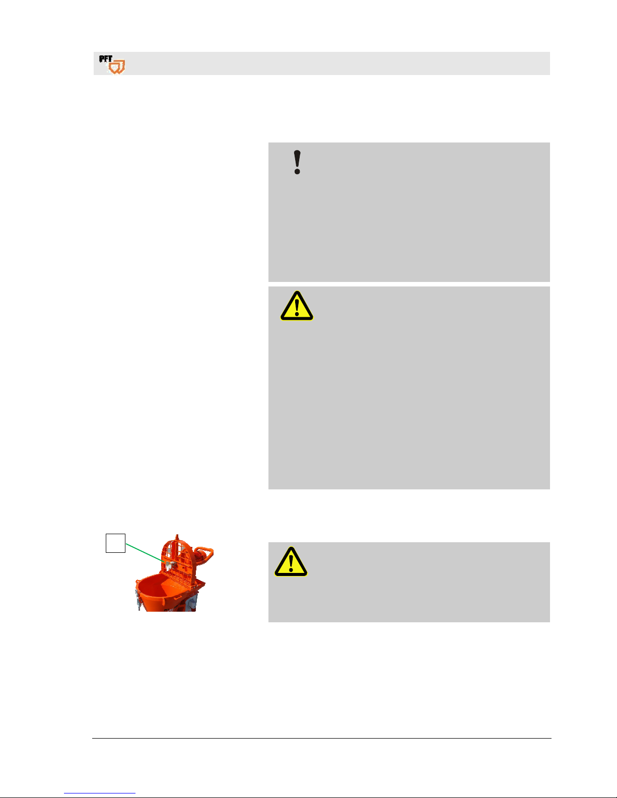
22.2 Closing the motor tilt flange
Fig. 18: Closing the motor tilt flange
DANGER!
Danger of crushing at the motor tilt flange!
There is a danger of crush injuries when closing
the motor tilt flange.
Never reach into the closing range of the motor
tilt flange.
1
Page 18
Mixing pump BOLERO 230V, 2,2kW Overview - Operation - Spare parts lists
Transport, packing and storage
18
2019-01-15
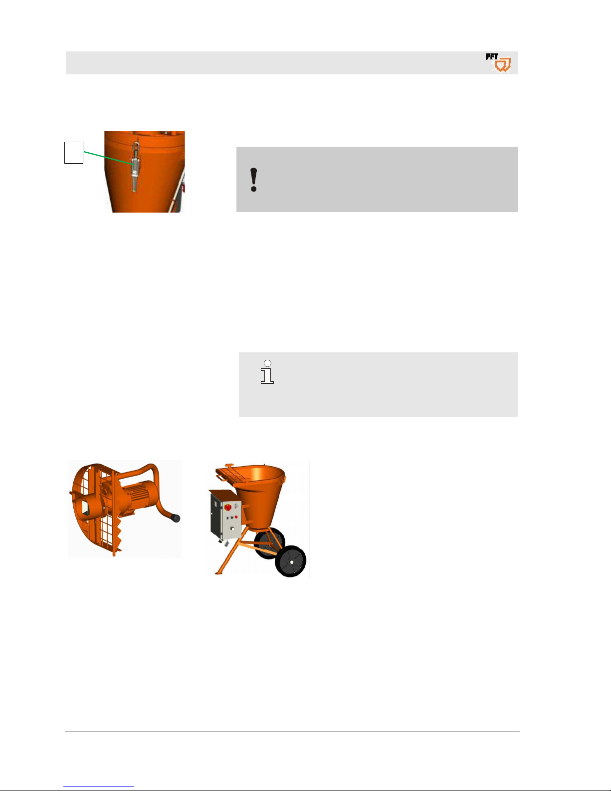
22.3 Close quick closure during transport
Fig. 19: Close quick closure
CAUTION!
Ensure in general terms that the quick closure (1) for
the protective grille is closed when moving the
machine.
22.4 Transport checklist
Inspect the goods for damage and missing parts immediately
after delivery.
If external transportation damage can be seen, proceed as follows:
Do not accept the delivery, or accept it only under reservations.
Note the damage on the transportation documents or
the delivery note of the carrier.
Submit the appropriate claim.
NOTE!
Always submit a claim for the defects as soon as
they are detected. Damage claims can only be
accepted within the applicable deadlines for
submission.
22.5 Transport in individual parts
Fig. 20: Gear motor with
protective grille
Fig. 21: Material container and
control cabinet
1. Take the machine apart for easier
transport.
2. The units gear motor with protective
grille, material container with
undercarriage and pump.
3. Loosen cable connections. Open linch
pins, remove gear motor with
protective grille from the undercarriage.
1
Page 19
Mixing pump BOLERO 230V, 2,2kW Overview - Operation - Spare parts lists
Transport, packing and storage
2019-01-15
19
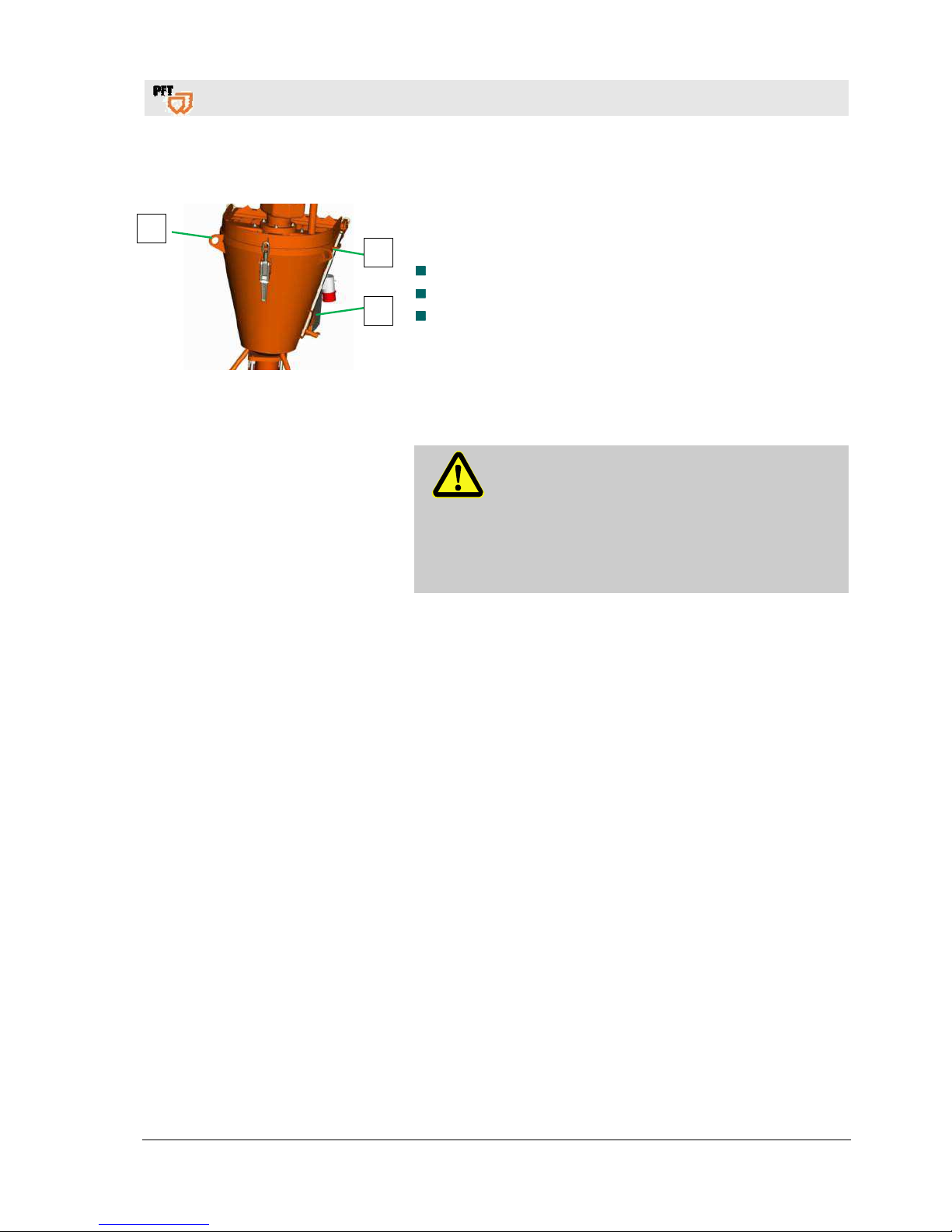
22.6 Transport by crane
Fig. 22: Crane transport
Attachment:
Remove loose parts (1) at the machine.
Attach ropes or belts at lifting rings (2).
Ensure that the package is straight, possibly observe
eccentric centre of gravity.
22.7 Transportation of operational machines
DANGER!
Danger of injury due to leaking mortar!
Injury to the face and eyes can occur.
Therefore:
Make sure all hoses are depressurised before
opening the couplings (note the indicator on
the mortar pressure gauge).
1. Carry out the following steps before transporting:
2. First unplug the main power cable.
3. Detach all other connected cables.
4. Remove the water supply lines.
5. Begin transport.
6. Remove loose parts during crane transport.
2
1
2
Page 20
Mixing pump BOLERO 230V, 2,2kW Overview - Operation - Spare parts lists
Packaging
20
2019-01-15
23 Packaging
On packaging The individual packages have to be packed in accordance with the
transport conditions to be expected. Only environmentally-friendly
materials were used for the packaging.
The packaging should protect the individual components until the
assembly from transport damage, corrosion and other damage.
Therefore do not destroy the packaging and remove only shortly
before the assembly.
Handling packaging materials If no agreement for the recovery of the packaging has been made,
separate materials according to type and size and reuse or recycle.
CAUTION!
Environmental damage due to wrong disposal!
Packaging materials are valuable raw materials
and many times they can be reused or
reconditioned and recycled.
Therefore:
– Dispose of packaging materials in an
environmentally-friendly way.
– Observe the applicable local disposal
regulations. If required hand over the disposal
to a specialist.
24 Operation
24.1 Safety
Personal protective equipment
The following protective equipment has to be worn for all operative
work:
Protective clothing
Protective goggles
Protective gloves
Safety shoes
Hearing protection
Breathing protection
NOTE!
Further protective equipment that is to be worn
when effective particular jobs will be pointed out
separately in the warning instructions of this
chapter.
Page 21
Mixing pump BOLERO 230V, 2,2kW Overview - Operation - Spare parts lists
Preparation
2019-01-15
21
Basic information
WARNING!
Risk of injury due to improper operation!
Improper operation may lead to serious damage to
persons or property.
Carry out all operating steps according to the
instructions in this user manual.
Prior to starting your work ensure that all covers
and protection devices are installed and work as
intended.
Never deactivate protection devices during
operation.
Ensure order and cleanliness in the work are!
Loose components and tools on top of another or
lying about pose potential accident risks.
Increased noise level may cause permanent
hearing deficiencies. At close range of the
machine 78 dB(A) can be exceeded due to
operational conditions. Close range is a distance
of less than 5 metres to the machine.
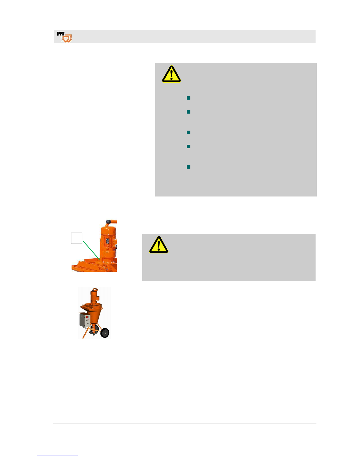
25 Preparation
Fig. 23: Grille cover
Prior to operating the machine carry out the following steps for
preparing the machine:
DANGER!
Rotating mixing shaft!
Risk of injury when reaching into the material container.
– During machine preparation and operation the grille
cover (1) must not be removed.
– Never reach into the running machine.
Fig. 24: Ensure stable stand
1. Put up the machine on a stable, even surface and secure against
unwanted movements:
Neither tilt nor roll off the machine.
Put up the machine in such a way that it cannot be hit by falling
objects.
The operating elements have to be freely accessible.
1
Page 22
Mixing pump BOLERO 230V, 2,2kW Overview - Operation - Spare parts lists
Fill water into the material container
22
2019-01-15
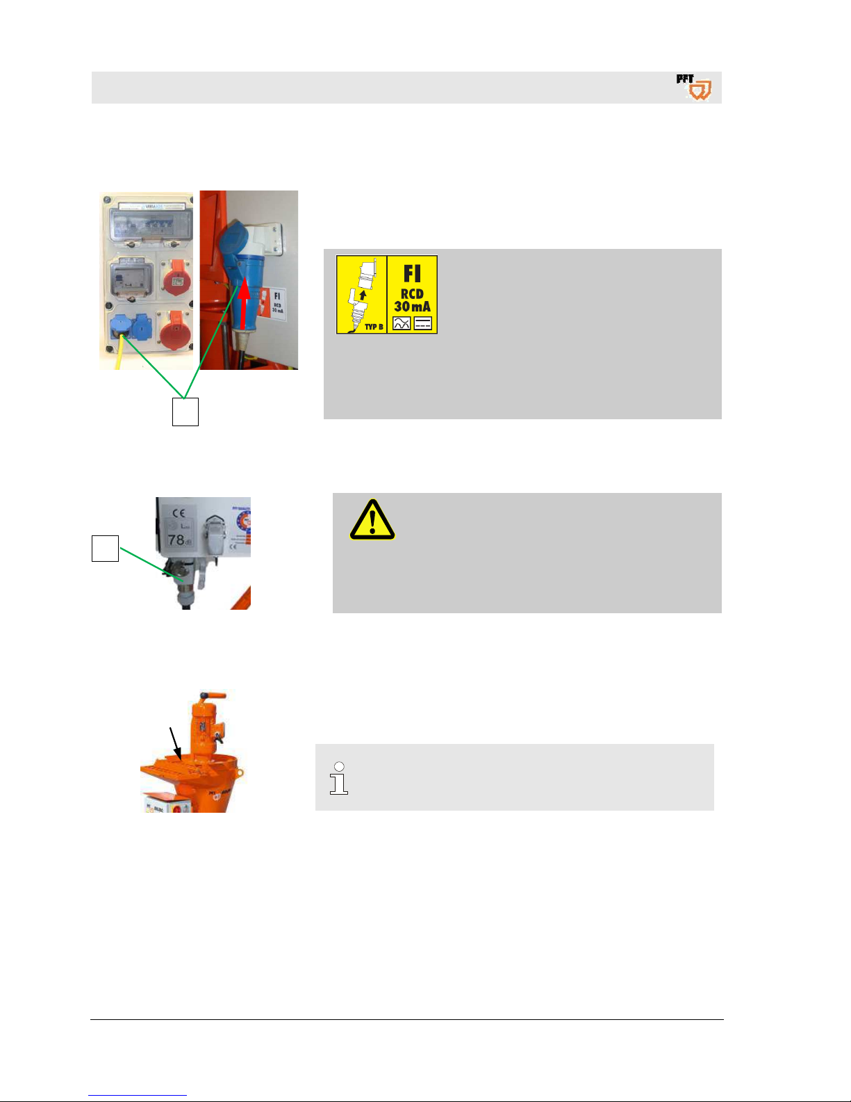
25.1 Connection of power supply
1
Fig. 25: Connect power
1. Connect the machine only to a 230V AC power supply line.
DANGER!
Danger to life from electric current!
The connecting cable must be secured
correctly:
Connect the machine only to a power
source with permissible FI circuit breaker
(30mA) RCD (Residual Current operated
Device) Type B, sensitive to all current
types, for the operation of frequency
converters.
25.2 Motor connecting cable for pump motor
Fig. 26: Motor connection cable
WARNING!
Danger of death due to rotating parts!
Improper operation can lead to serious injuries
or equipment damage.
The respective drives (motors) may only be
operated via the corresponding control box of
the machine.
1. Connect motor connecting cable (1) to control cabinet.
26 Fill water into the material container
Fig. 27: Fill in water
1. Pour about 2 litres of water into the material container.
NOTE!
Never let the pump run dry as this reduces the
service life of the pump.
1
Page 23
Mixing pump BOLERO 230V, 2,2kW Overview - Operation - Spare parts lists
Mortar pressure gauge
2019-01-15
23
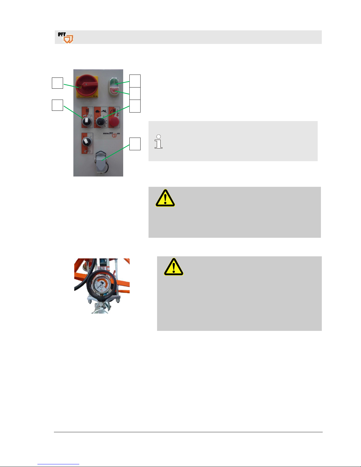
26.1 Trial run
Fig. 28: Trial run
1. Turn main switch (1) to position "I".
2. Put on dummy connector (2).
3. Press green operating button (3) control voltage "ON".
4. White control lamp (4) lights up.
5. Turn potentiometer (5) to level 4.
6. Turn selector switch (6) to the right.
NOTE!
In anticlockwise mode of the agitator the material is
mixed continuously. In clockwise mode the feed
pump is connected and pumps the ready-mixed
material to the point of use.
7. Let the machine run shortly until the water has been pumped out of
the machine container.
8. Switch off the machine at selector switch (6) (position "0").
WARNING!
Danger of death due to rotating parts!
Improper operation can lead to serious injuries
or equipment damage.
The respective drives (motors) may only be
operated via the corresponding control box of
the machine.
27 Mortar pressure gauge
Fig. 29: Mortar pressure gauge
DANGER!
Operating pressure too high!
Machine parts can open in an uncontrolled manner
and injure the operator.
– Do not operate the machine without mortar
pressure gauge.
– Use only mortar hoses with a permissible
operating pressure of at least 40 bar.
– The burst pressure of the mortar hose must
reach at least 2.5 times the value of the
operating pressure.
3
4
5
2
1
6
Page 24
Mixing pump BOLERO 230V, 2,2kW Overview - Operation - Spare parts lists
Mortar hoses
24
2019-01-15
28 Mortar hoses
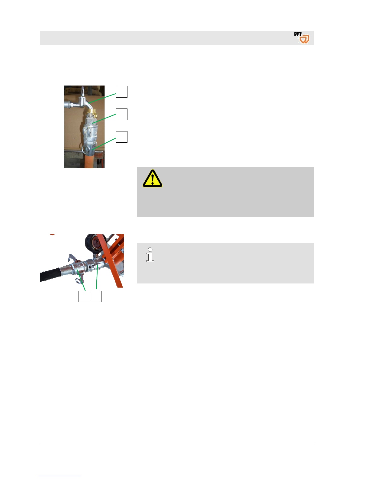
28.1 Prepare mortar hoses
Fig. 30: Prepare mortar hose
1. Connect the cleaner coupling (1) at the water extraction valve (2).
2. Connect mortar hose (3) and water.
3. More mortar hose and cleaner coupling again and separate.
4. Remove all the water from the mortar hose.
5. Pre-lubricate the mortar hose with about one litre of wallpaper
paste.
6. The wallpaper paste is mixed through the mortar hose with the first
mixing.
7. Collect the wallpaper paste in suitable container and dispose of as
per regulations.
DANGER!
Torn off hoses can beat about and injure bystanders!
Never loosen the hose couplings as long as there is
pressure on the mortar hoses (check mortar pressure
gauge)! The mix could burst out under pressure and
result in serious injuries, especially injuries to the
eyes.
28.2 Connect mortar hose
1 2
Fig. 31: Connect mortar hose
1. Connect mortar hose (1) at the mortar pressure gauge (2).
NOTE!
Ensure clean and correct connection of the couplings!
Ensure tightness. Dirty couplings and rubber seals are
not watertight, and water might leak under pressure
inevitably leading to blockages.
2. Lay mortar hoses in large radius so that no kinks form in the hoses.
3. Attach risers carefully in order to prevent them from tearing off
under their own weight.
2
1
3
Page 25
Mixing pump BOLERO 230V, 2,2kW Overview - Operation - Spare parts lists
Putting the machine into operation
2019-01-15
25
28.3 Connect Zargomat and gluing gun
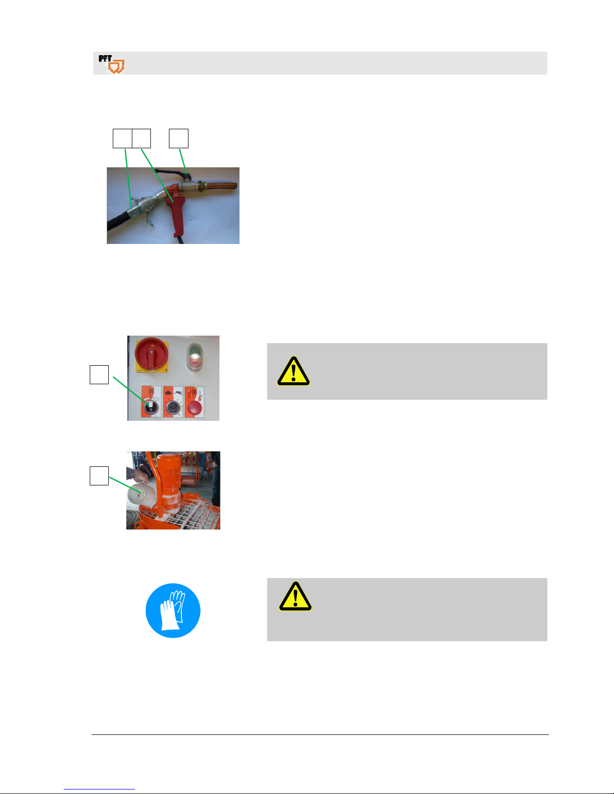
2 1 3
Fig. 32: Gluing gun
1. Connect Zargomat and gluing gun (1) to mortar hose (2).
2. Ensure that the ball valve (3) at the gluing gun is closed.
29 Putting the machine into operation
29.1 Start off machine
Fig. 33: Mixing
Attention!
Never fill the material container with the mixer
standing still.
1. Turn selector switch (1) to the left for mixing the bagged goods.
Fig. 34: Fill in water
2. Pour specified water quantity (mixing water) (2) for one material
sack into the material container.
29.2 Fill machine with factory prepared dry material
DANGER!
Risk of injury at the sack opener!
The sharp edges of the sack opener pose a risk of
injury.
– Wear safety gloves.
1
2
Page 26
Mixing pump BOLERO 230V, 2,2kW Overview - Operation - Spare parts lists
Putting the machine into operation
26
2019-01-15
29.3 Hazardous dusts
Warning!
Health hazard caused by dust!
In the long term, inhaled dust can lead to lung
damage or have other adverse health effects.
NOTE!
The machine operator or the person working in the
dusty area always have to wear a dust protection
mask when filling the machine!
The rules of the Committee on Dangerous
Substances (AGS) can be found under Technical
Rules for Dangerous Substances (TRGS 559).
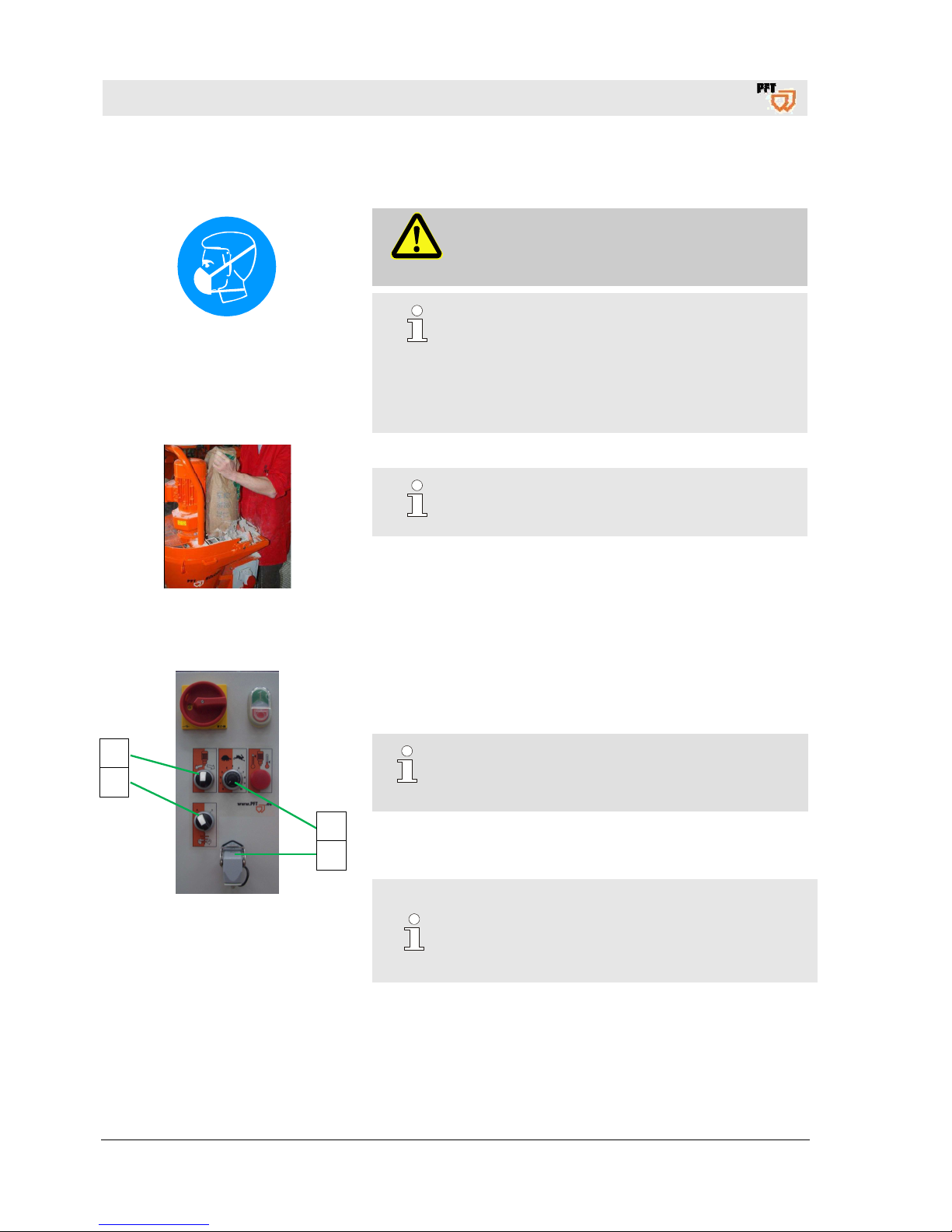
Fig. 35: Fill in bagged material
1. Empty the bagged material into the material container.
NOTE!
For initial filling with bagged material slowly pour
half of the first bag into the material container!
2. Mix material well.
3. Turn selector switch operating mode "mixing OFF pumps" to
position "0".
29.4 Connect remote control
Fig. 36: Remote control
1. Remove dummy plug (1) from control cabinet.
2. Connect the remote control cable of the Zargomat and gluing
gun at the control cabinet.
NOTE!!
The machine can be switched on and off using the
ON/OFF switch at the Zargomat and gluing gun.
3. Turn selector switch (2) to the right.
4. Using the potentiometer (3) the engine speed is changed, thus
also the required material quantity.
NOTE!
When the selector switch (4) to position "1" on the
machine with conveyor breaks (off by remote control)
automatically in the mixing process. The material is
mixed continuously.
2
4
3
1
Page 27
Mixing pump BOLERO 230V, 2,2kW Overview - Operation - Spare parts lists
Switching on
2019-01-15
27
30 Switching on
30.1 Apply material
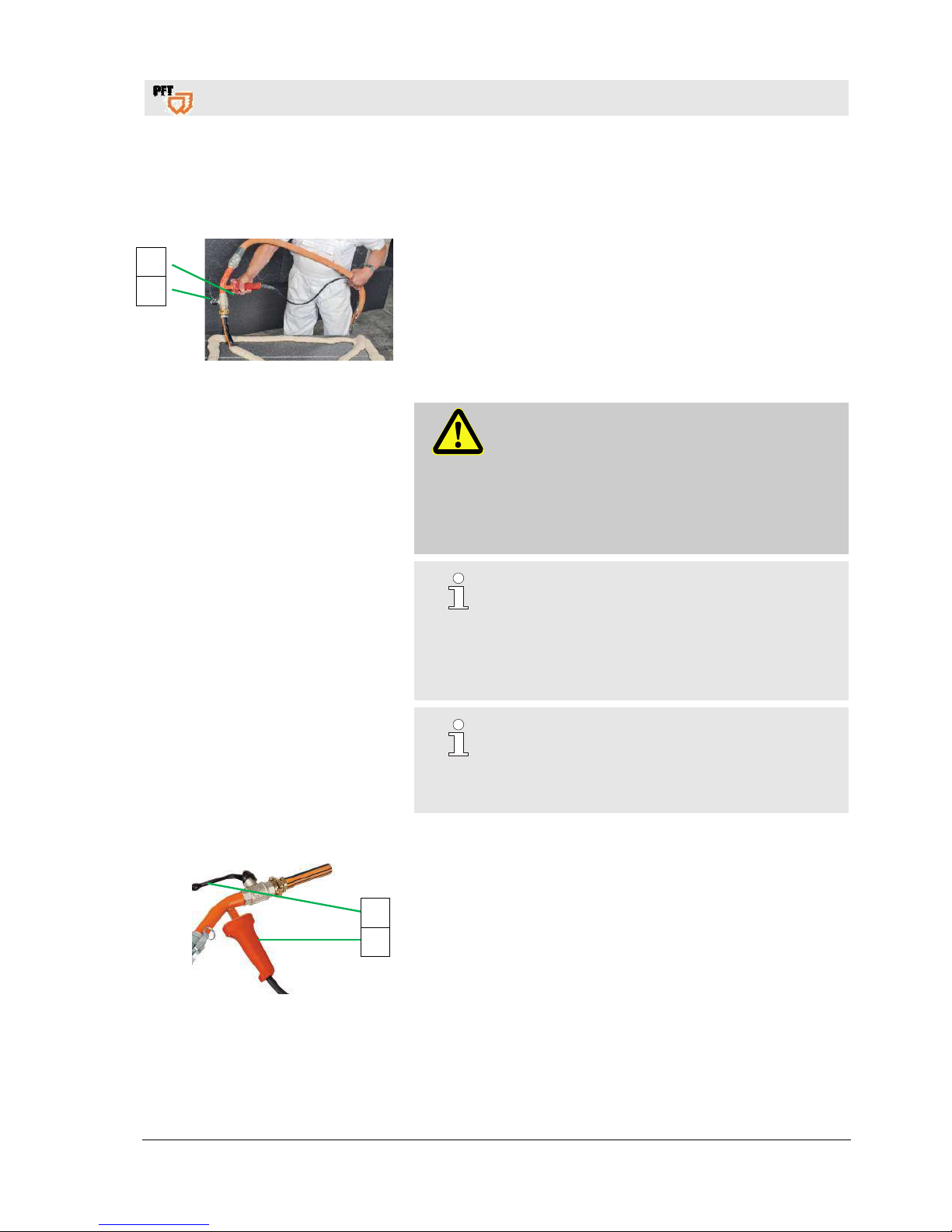
Fig. 37: Apply material
1. Point the gluing gun in the direction of the object to be
processed.
2. Ensure that nobody is in the discharge area of the gluing gun.
3. Open the ball valve (1).
4. Actuate the ON/OFF switch (2) at the gluing gun.
5. The conveying process of the material starts.
DANGER!
Risk of injury from discharged mortar!
Discharged mortar may lead to injuries to eyes and
face.
– Never look into the spraying device.
– Always wear protective goggles.
– Always position yourself in such a way that you
are not hit by the mortar being discharged.
NOTE!
The possible conveying distance depends mainly
on the flowability of the mortar. Heavy, sharpedged mortar has poor flow characteristics. Runny
materials have good flow characteristics.
If 20 bar operating pressure are exceeded thicker
mortar hoses have to be used.
NOTE!
If the water quantity is too little even mixing and
spraying is no longer guaranteed; blockages may
form inside the hose and high wear of the pump
parts will become an issue.
30.2 Switching off the machine
Fig. 38: Switching off the machine
1. Actuate the ON/OFF switch (1) (switching off).
2. The machine stops.
3. Close ball valve (2).
2
1
2
1
Page 28
Mixing pump BOLERO 230V, 2,2kW Overview - Operation - Spare parts lists
Interruption of work
28
2019-01-15
30.3 Switch machine on again
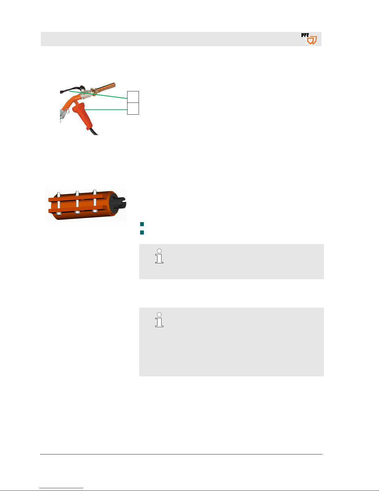
Fig. 39: Switch on machine
1. Open the ball valve (1).
2. Actuate ON switch (2) at the gluing gun (switching ON).
3. The machine starts again.
30.4 Re-tighten pump
Abb. 40: Tighten pump
1. In the case of decreasing feed pressure the stator can be retightened.
2. Do not re-tighten the pump during operation.
3. Pump parts that do not deliver the required feed pressure when
tightened have to be replaced.
When replacing the pump it has to be ensured that
all screws of the retaining clamp are equally tightened.
In case of rubber stators, the tension rod bolts are not tightened too
much and that the sheath end lies flush and centrally in the flanges.
NOTE!
Store the assembled pump (rotor in stator) only for a
few days as rotor and stator can permanently connect
to each other in case of prolonged storage.
31 Interruption of work
NOTE!
Always observe the setting time of the material to be
processed:
Clean the system and mortar hoses depending on the
setting time of the material and the length of the
interruption (pay attention to outside temperature).
The guidelines of the material manufacturers have to be
observed regarding breaks.
1
2
Page 29
Mixing pump BOLERO 230V, 2,2kW Overview - Operation - Spare parts lists
Stopping in case of emergency
2019-01-15
29
32 Stopping in case of emergency
32.1 Emergency OFF switch
Switching off in an emergency Machine movements and the energy supply must be disabled as
quickly as possible in dangerous situations.
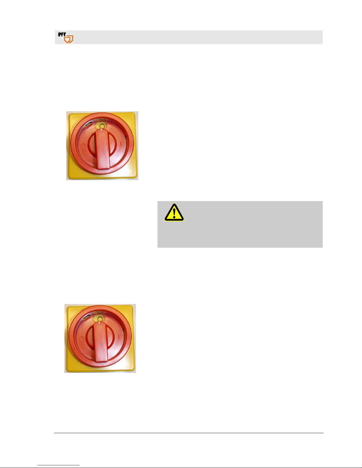
Fig. 41: Switching off
Proceed as follows in the event of an emergency:
1. Turn the main switch to position “0”.
2. Secure the main switch against being activated again using
a padlock.
3. Inform supervisors at the site.
4. If necessary, call emergency services.
5. Remove persons from the danger zone and carry
out first-aid measures.
6. Ensure emergency vehicles have unobstructed access.
7. If the seriousness of the emergency warrants this, inform
the responsible authorities.
8. Assign specialist personnel to begin rectifying the fault.
WARNING!
Danger of death due to premature restarting!
All persons in the danger zone are at extreme
risk when the machine is switched back on.
Ensure that the danger zone is clear before
switching the machine back on.
9. Check the equipment before switching it back on and ensure
that all safety devices are in place and functioning properly.
33 Measures to be taken in the event of a power failure
33.1 Turning the main switch to position “0”
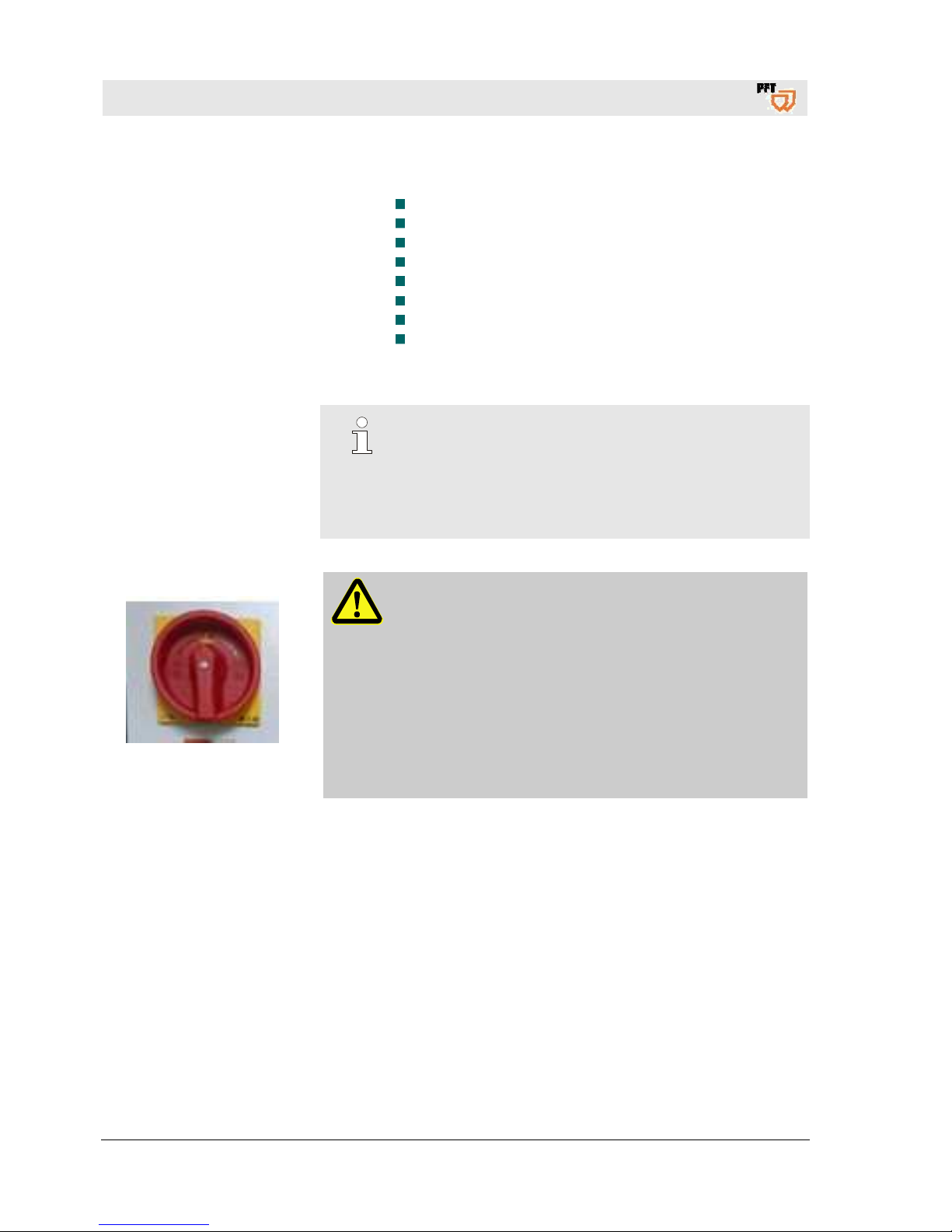
Fig. 42: Switch at position “0”
1. 1. Close the ball valve on the sprayer.
2. Turn the main switch to position “0”.
3. Disconnect the connector plug from the air compressor.
4. Have the power supply connection checked by an expert.
Page 30
Mixing pump BOLERO 230V, 2,2kW Overview - Operation - Spare parts lists
Measures to be taken in the event of a power failure
30
2019-01-15
33.2 Discharging mortar pressure
1 2
Fig. 43: Checking the mortar pressure
DANGER!
Overpressure on the machine!
When opening machine components, these can fly
open in an uncontrolled manner and injure the
operator.
Only open the machine if the pressure has fallen
to “0 bar”.
DANGER!
Danger of injury due to leaking mortar!
Escaping mortar can lead to injuries to the eyes
and face.
Therefore:
Never look into the spray gun.
Always wear protective goggles.
Always position the machine so that you cannot
be hit should mortar escape.
Cover working area with foil.
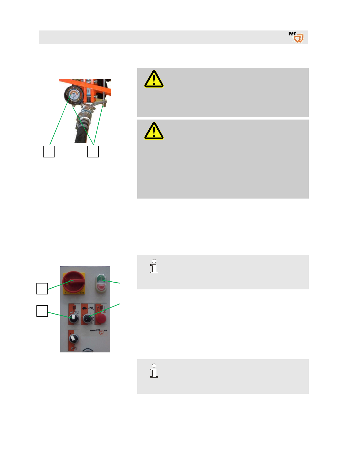
1. Open the ball valve.
2. Check the mortar pressure gauge (1) to see if the pressure has
fallen to “0 bar”. If necessary, discharge any mortar pressure by
unscrewing the nuts (2) slightly.
3. Afterwards re-tighten the nuts (2).
33.3 Switching on the machine again after a power failure
Fig. 44: Undervoltage trigger
NOTE!
The BOLERO is equipped with an undervoltage
trigger. In the event of a power failure, the system
must be started as follows.
1. Turn the selector switch (1) to the “Zero” position (middle position).
2. Close ball valve on gluing gun.
3. Turn the main switch (2) to the “I” position.
4. Press green operating button (3) control voltage "ON".
5. Using the potentiometer (4) the engine speed is changed, thus
also the required material quantity.
6. Open the ball valve and press the switch on the gluing gun.
7. The machine starts again
NOTE!
In the event of a prolonged power failure,
the BOLERO and the material hoses
should be cleaned immediately.
3
4
2
1
Page 31
Mixing pump BOLERO 230V, 2,2kW Overview - Operation - Spare parts lists
Work on troubleshooting
2019-01-15
31
34 Work on troubleshooting
34.1 Reaction in the event of faults
Reaction in the event of faults
Basically applies:
1. In the event of faults presenting immediate danger to persons
or property activate the emergency OFF function immediately.
2. Determine cause for fault.
3. If the rectification of faults requires works in the danger zone,
switch off the system and secure against restarting.
4. Inform the manager on site immediately about the fault.
5. Depending on the type of fault commission authorised skilled
personnel or rectify the fault yourself.
NOTE!
The following fault table gives information on who
is authorised to rectify the fault.
34.2 Fault displays
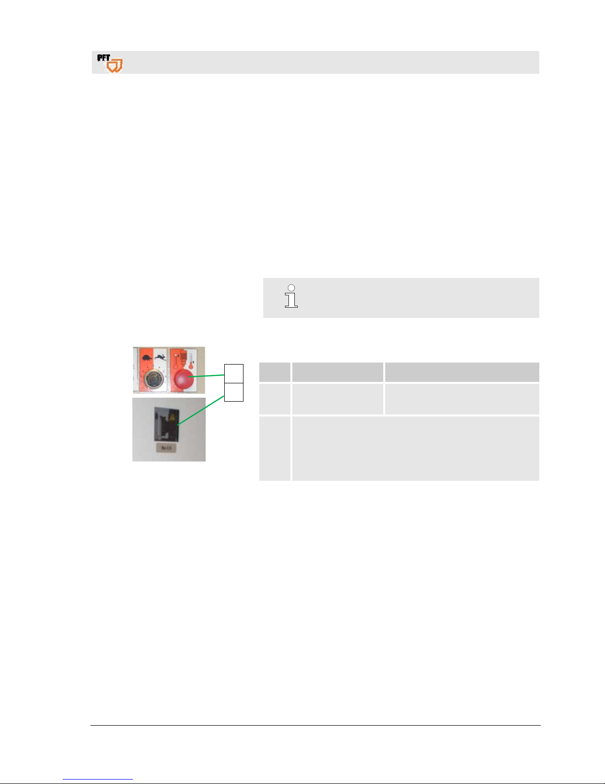
Fig. 45: Fault displays
The following installation indicates faults:
Pos. Light signal Description
1 Red pilot lamp
Lights up in case of fault in the
frequency converter.
2
Faults in the frequency converter are shown on the
display.
Corrective measures are described in the attached quick
start guide frequency converter V1000.
34.3 Faults
The following chapter describes possible causes for faults and the
activities carried out for their rectification.
In case faults occur frequently shorten the maintenance intervals in
accordance with the actual load.
In the event of faults that cannot be rectified by means of the
following notes, kindly contact the dealer.
1
2
Page 32

Mixing pump BOLERO 230V, 2,2kW Overview - Operation - Spare parts lists
Work on troubleshooting
32
2019-01-15
34.4 Safety
The works for the rectification of faults described here can be
carried out by the operator, unless marked otherwise.
Some works must be carried out only by specially trained skilled
personnel or exclusively by the manufacturer. Information on
this can be found in the description of the individual faults.
Works at the electrical system must be carried out by qualified
electricians only.
Personal protective equipment
The following protective equipment has to be worn for all
maintenance work:
Protective clothing
Protective goggles
Protective gloves
Safety shoes
34.5 Table of faults
Fault Possible cause Rectification of faults Rectification by
Machine
does not
start
power
Power supply not in order Repair power supply Service engineer
Main switch not activated Activate main switch Operator
RCCB was triggered Reset RCCB Service engineer
Motor protection switch triggered
Turn motor protection switch in
control cabinet to position 1
Service engineer
"Operation button ON" not pressed Press "operation button ON" Operator
Contactor defective Change contactor Service engineer
Fuse defective Change fuse Service engineer
Machine
does not
start
material
Thickened material in material
container
Remove thickened material or add
water
Operator
Excessively dry material in pump part Remove pump and clean Service engineer
Pump
motor
does not
start
Pump motor defective Exchange pump motor
Service engineer
Connection cable defective Change connection cable
Service engineer
Plug or inbuilt socket defective Change plug or inbuilt socket
Service engineer
Motor protection switch defective or
triggered
Change motor protection switch or
reset
Service engineer
Mortar
flow
ceases
(air
bubbles)
Poor mixture Add more water
Let mixture be mixed for a longer
time
Operator
Clumped material
Add more water or clean agitator
or replace
Operator
Agitator defective Replace agitator Operator
Driving dog defective Replace driving dog Service engineer
Page 33

Mixing pump BOLERO 230V, 2,2kW Overview - Operation - Spare parts lists
Conveying stationary / clogging
2019-01-15
33
Mortar
flow "thickthin"
Rotor worn or defective Replace rotor Service engineer
Stator worn or clamping bracket
tightened too little
Replace stator or re-tighten
clamping bracket
Service engineer
Clamping bracket defective (oval) Replace clamping bracket Service engineer
Inner wall of mortar hose defective Replace mortar hose Operator
Rotor too deep in pressure flange Replace pressure flange Service engineer
No original PFT spare parts Use original PFT spare parts Service engineer
Control
lamp red,
fault lights
up
Overload due to the pump getting
blocked with dry material
Remove pump and clean Service engineer
Overload due to low water volume Add more water when starting off Operator
Motor protection switch pump motor
triggered
Reactivate protection switch Service engineer
35 Conveying stationary / clogging
Clogging might form in the mortar hoses for several reasons. This means that the material to be conveyed
remains stuck in the mortar hoses and cannot be pumped to the hose end.
35.1 Signs for clogging
Implementation by operator:
Blockages can occur in the pressure flange or in the mortar
hoses.
Indications are:
rapidly increasing pressure head,
blocking of pump,
running difficulties or blockage of the pump motor,
expansion and turning of the mortar hose,
no material discharge at the hose end.
Page 34
Mixing pump BOLERO 230V, 2,2kW Overview - Operation - Spare parts lists
Conveying stationary / clogging
34
2019-01-15
35.2 Causes for blockages:
Highly worn mortar hoses,
work interruptions,
badly greased mortar hoses,
residual water in mortar hose,
clogging of the pressure flange,
strong tapering at the couplings,
kink in mortar hose,
badly pumpable and demixed materials.
35.3 Earlier damage to the mortar hose
NOTE!
If in the event of a machine fault by material clogging the
pressure in the mortar hose exceeds 60 bar, even only
temporarily, replacement of the mortar hose is
recommended as there might be damage in the hose that is
not externally visible.
35.4 Removal of clogging in hoses
Fig. 46: Switching off
DANGER!
Danger from discharged material!
Never loosen the hose couplings as long as the pressure
head is reduced! Material to be conveyed can be
discharged under pressure and cause injuries particularly to
the eyes.
Persons commissioned with the cleaning of clogged hoses
have to wear personal protective equipment (protective
goggles, gloves) for safety reasons, and to position
themselves in such a way that they cannot be hit by
discharged material. Other persons have to clear the area.
Page 35
Mixing pump BOLERO 230V, 2,2kW Overview - Operation - Spare parts lists
Conveying stationary / clogging
2019-01-15
35
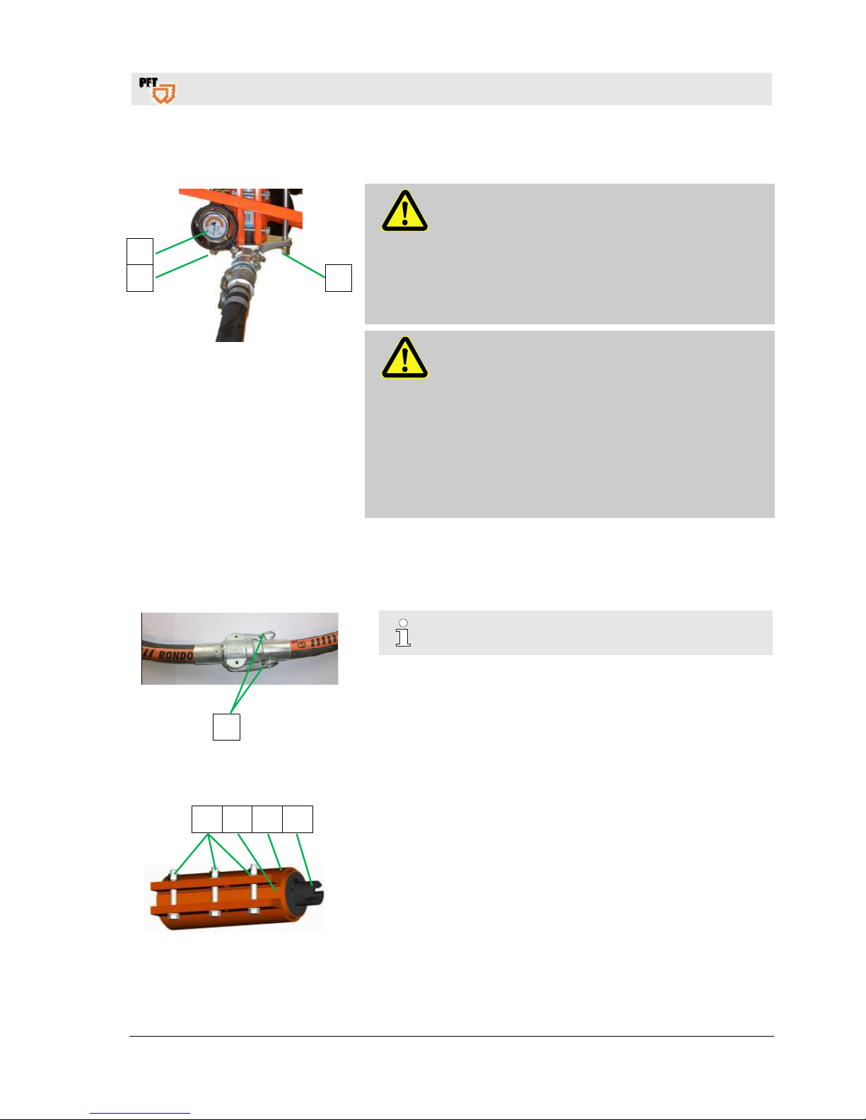
35.5 Risk of injury to due overpressure
Fig. 47: Checking the grout pressure
DANGER!
Overpressure on the machine!
When opening machine components, these can
fly open in an uncontrolled manner and injure
the operator.
Only open the mortar hoses if the mortar pressure
gauge (1) indicates the pressure has fallen to
“0 bar”.
DANGER!
Danger of injury due to leaking mortar!
Escaping mortar can lead to injuries to the eyes
and face.
Therefore:
Always wear protective goggles.
Protective clothing, protective gloves, safety shoes,
ear protection.
Always position the machine so that you cannot
be hit should mortar escape.
1. Undo both nuts (2) on the pressure flange slightly to ensure
the residual pressure can escape.
2. As soon as the pressure has dropped to “0 bar”, tighten the nuts
(2) again.
3
Fig. 48: Detaching the coupling
NOTE!
Immediately clean the mortar hoses.
3. Cover coupling connections with tear-resistant film.
4. Release cam lever (3) and hose connections.
5. Remove blockage by tapping or shaking at the point of
the blockage.
6. If necessary, introduce a flushing hose into the mortar hose and
flush out the material (PFT flushing hose item no. 00113856).
35.6 Cleaning the pump
1 2 3 4
Fig. 49: Cleaning the pump
1. Remove pump unit
2. Loosen nuts from the clamping bracket (1).
3. Push the stator (2) out of the clamping bracket (3).
4. Push the rotor (4) out of the stator (2) and clean.
5. Clean pressure flange.
6. Clean material container and agitator.
7. Reassemble completely the pump unit.
1
2
2
Page 36
Mixing pump BOLERO 230V, 2,2kW Overview - Operation - Spare parts lists
End of shift / Cleaning
36
2019-01-15
36 End of shift / Cleaning
36.1 Switching off the energy supplies
Securing against restarting
DANGER!
Danger of death due to unauthorised restarting!
When working on the machine, there is a danger of
unauthorised switching on of the electrical supply.
This puts those in the danger area at extreme risk.
Before starting work, switch off all electrical power
supplies and secure them against being switched
back on again.
36.2 Cleaning BOLERO
CAUTION!
Water can enter sensitive machine parts!
Before cleaning the machine, seal all openings
where water could enter and impair the safety
and functions of the machine (e.g.: electric motors
and control boxes).
NOTE!
Do not aim the water jet at electrical components,
such as the gear motor or control box.
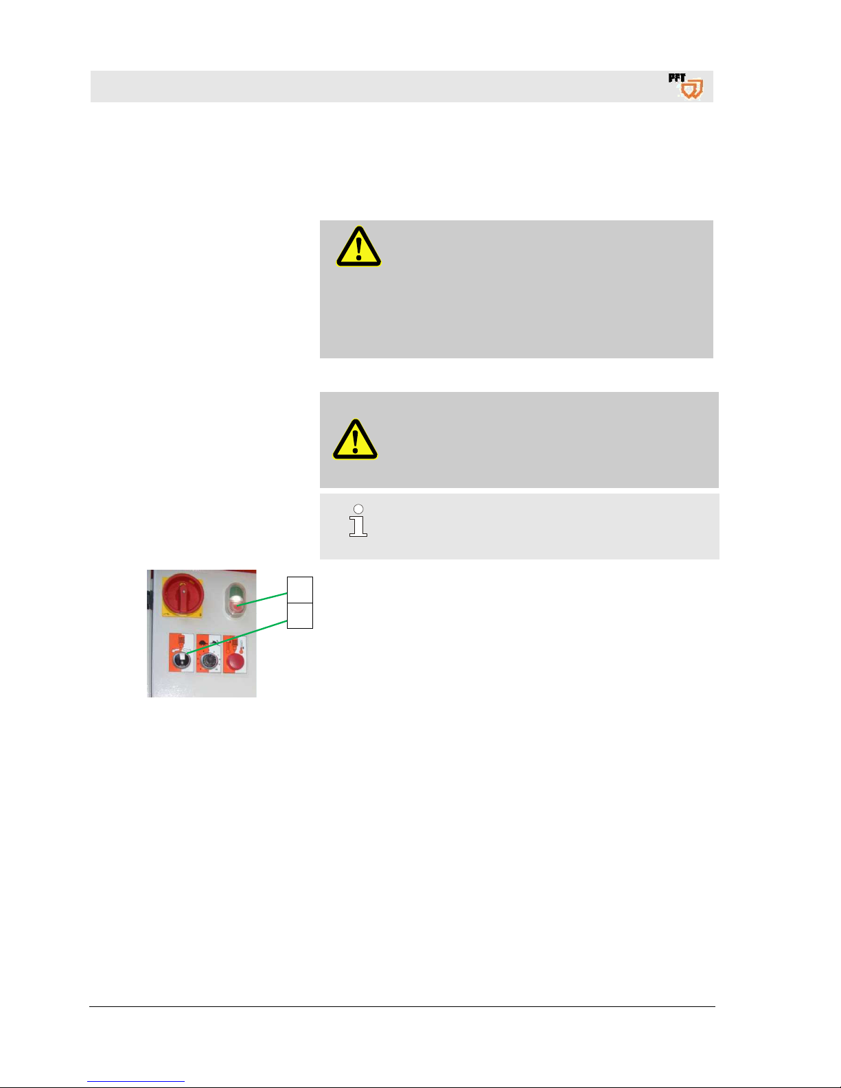
Fig. 50: Switching off
The machine has to be cleaned daily after work and in case of
longer breaks.
Switching off the machine:
1. Turn selector switch (1) to middle position.
2. Press red operating button (2) control voltage "OFF".
3. Open ball valve at the glue gun so that the residual pressure in
the hose can escape.
2
1
Page 37
Mixing pump BOLERO 230V, 2,2kW Overview - Operation - Spare parts lists
End of shift / Cleaning
2019-01-15
37
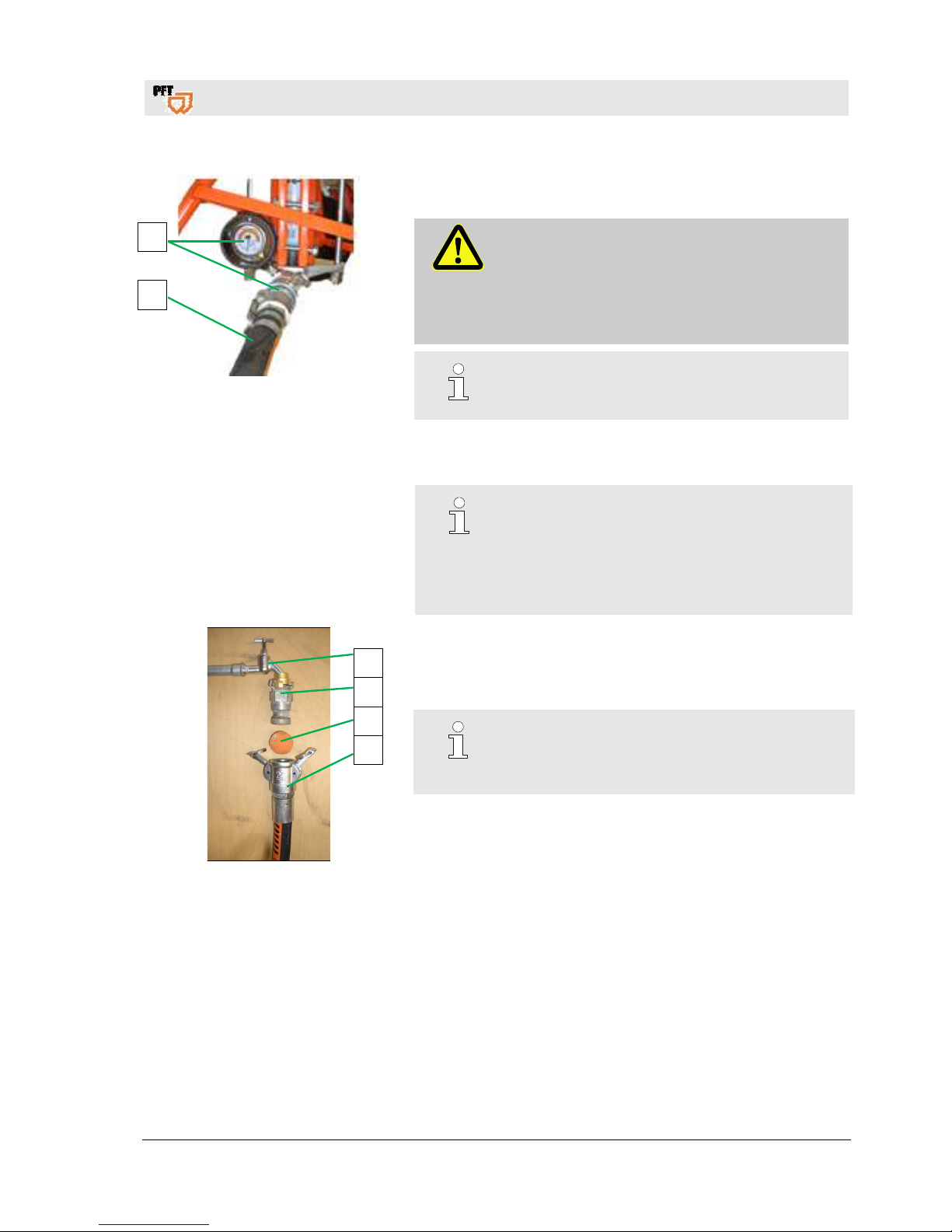
Fig. 51: Mortar pressure to "0 bar"
4. Check at the mortar pressure gauge (1) if the mortar pressure is
at "0 bar".
DANGER!
Overpressure on the machine!
When opening machine parts they can open in an
uncontrolled manner and injure the operator.
– Open machine only when the pressure is at "0
bar".
NOTE!
Mortar hoses and spraying device have to be
cleaned immediately after finishing work.
5. Disconnect mortar hose (2) from mortar pressure gauge (1).
36.3 Clean mortar hose
NOTE!
Material remains that can deposit on the inside of
the mortar hose, may cause damages, continue to
build up and narrow the diameter. Clean mortar
hoses therefore are indispensable to have troublefree conveying next time the hoses are being used.
Fig. 52: Clean mortar hoses
1. Connect the cleaner coupling (1) at the water extraction valve
(2).
2. Press the water saturated sponge ball (3) into the mortar hose
(4).
NOTE!
Do not rinse the mortar hoses with water before.
The material has to be pushed out of the hoses with
the sponge ball.
3. Connect the mortar hose (4) with the spraying device at the
cleaner coupling (1).
4. Open the water extraction valve (2) until the sponge ball (3) exits
the spraying device.
5. In case of strong soiling repeat this process.
6. In case of different hose diameters, the mortar hoses have to be
cleaned separately with the matching sponge balls.
3
4
2
1
3
4
Page 38
Mixing pump BOLERO 230V, 2,2kW Overview - Operation - Spare parts lists
End of shift / Cleaning
38
2019-01-15
36.4 Clean Zargomat and gluing gun
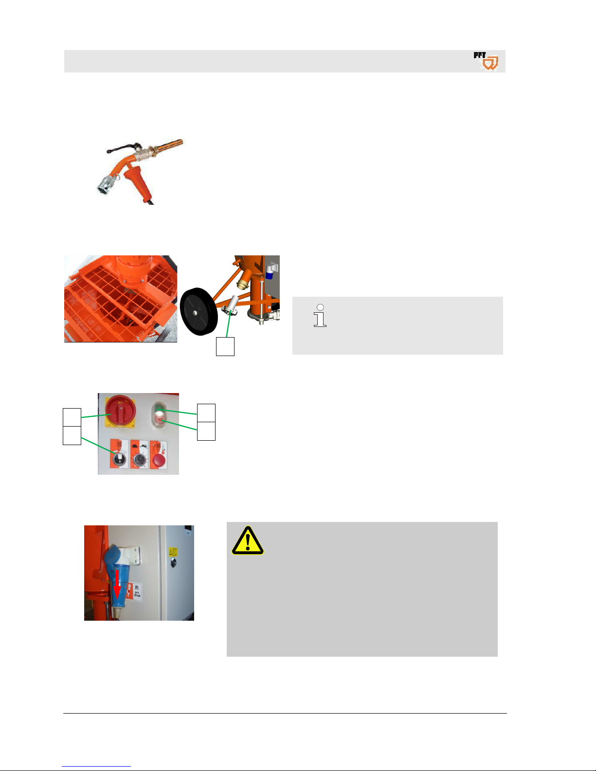
Fig. 53: Clean Zargomat gun
1. Remove the remote control cable of the Zargomat and gluing
gun from the control cabinet.
2. Disconnect the Zargomat and gluing gun from the mortar hose.
3. Clean the Zargomat and gluing gun.
36.5 Clean he material container
Fig. 54: Cleaning
Open the dummy cap (1).
Hose out the material container with a water jet.
NOTE!
Do not direct the water jet on electrical
parts, such as gear motor or control
cabinet.
36.6 Switching on the machine
Fig. 55: Switching on
1. Press green operating button (1) control voltage "ON".
2. Turn selector switch (2) to the right to pump.
3. Pump the water from the material container until clear water
emerges from the mortar hose gauge.
4. Switch off machine at the red operating switch.
5. Turn main switch (3) to position "0".
36.7 Removing the connection cable
Fig. 56: Removing the connection cable
DANGER!
Danger of death due to unauthorised restarting!
When working on the machine, there is a danger of
unauthorised switching on of the electrical supply.
This puts those in the danger area at extreme risk.
Therefore:
Before starting work, switch off the electrical
power supply and secure it against being
switched back on again.
Interrupt the power supply by removing
the connection cable.
1
4
2
1
3
Page 39
Mixing pump BOLERO 230V, 2,2kW Overview - Operation - Spare parts lists
End of shift / Cleaning
2019-01-15
39
Securing against restarting
DANGER!
Danger of death due to unauthorised restarting!
When working on malfunctions, there is a danger of
unauthorised switching on of the electrical supply.
This puts those in the danger area at extreme risk.
Therefore:
Before starting work, switch off all electrical power
supplies and secure them against being switched
back on again.
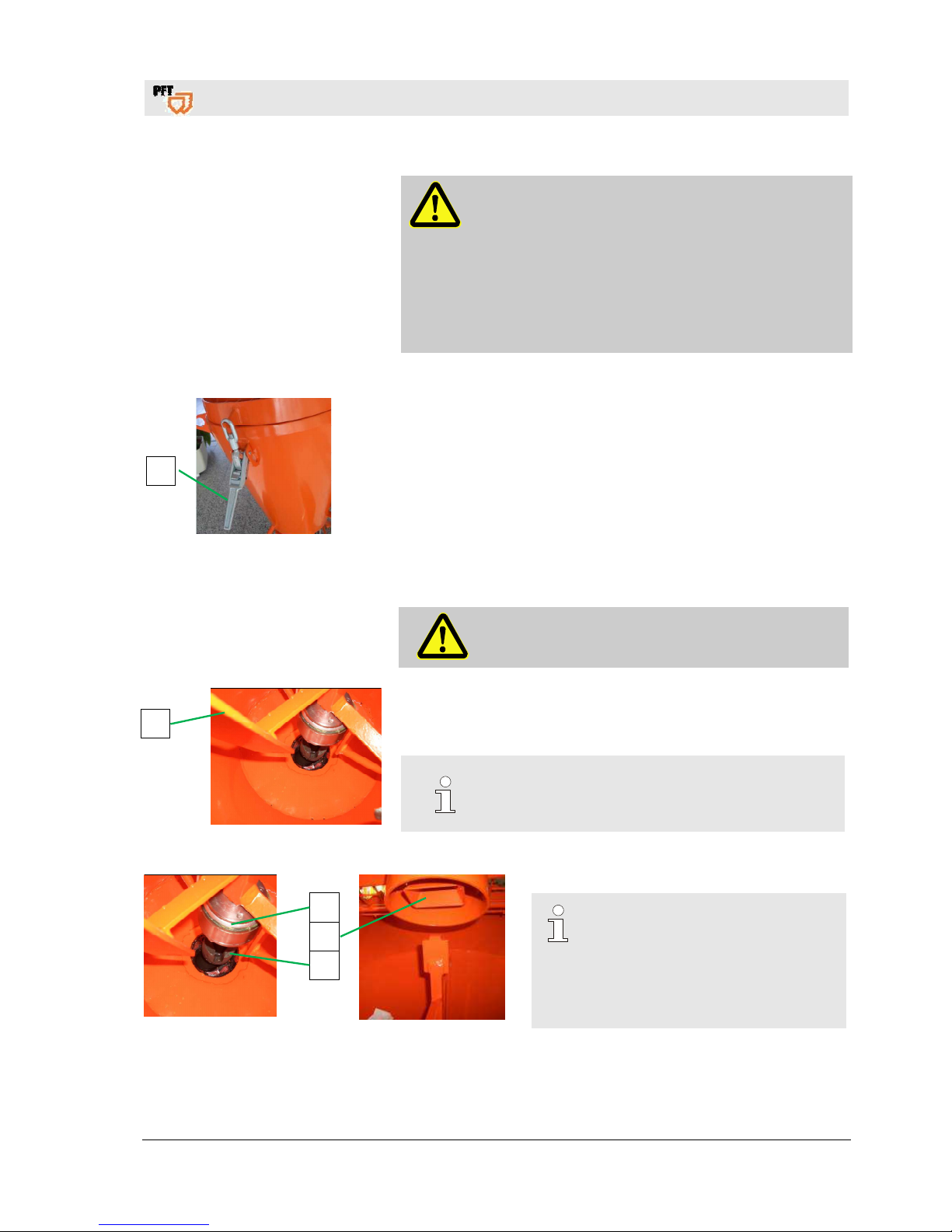
36.8 Open protective grille
Fig. 57: Open the protective grille
1. Open the quick closure (1) and tip the motor with protective
grille.
36.9 Clean material container
DANGER!
Never reach into rotating or moving parts when the
machine is running!
Fig. 58: Agitator
1. Remove the agitator (1) from the material container and
completely clean from material remains.
2. Clean material container.
NOTE!
Do not use aggressive detergents.
3. Put back the agitator after cleaning.
Fig. 59: Put back agitator
NOTE!
When inserting the agitator (1)
ensure that the freewheel of the
agitator (2) in the head of the rotor
(3) grips properly into the drive dog
(4) when closing the protective
grille.
1
1
2
4
3
Page 40
Mixing pump BOLERO 230V, 2,2kW Overview - Operation - Spare parts lists
Risk of frost
40
2019-01-15
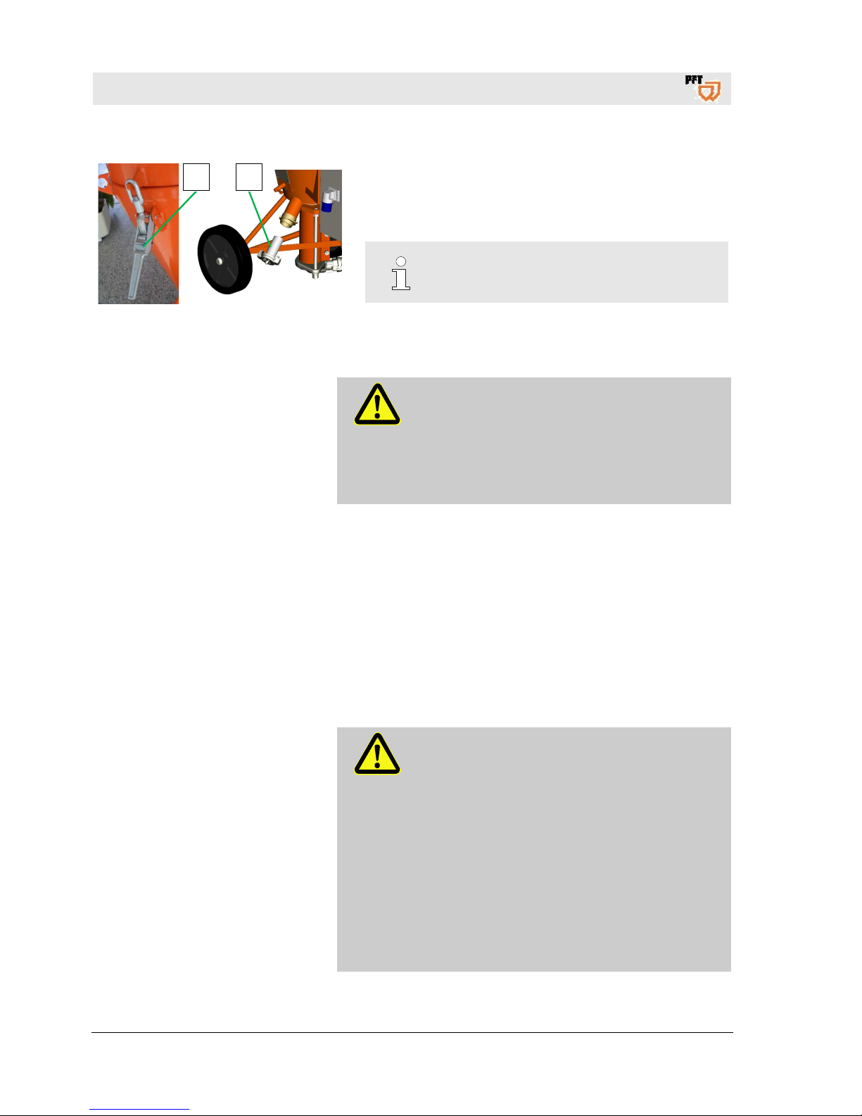
Fig. 60: Close protective grille
4. Close quick closure (5).
5. Close cleaning cover (6).
NOTE!
Ensure that the quick closure is always
closed.
37 Risk of frost
CAUTION!
Damage by frost!
Water that expands inside the machine during frost
can cause severe damage.
– In case of danger of frost the machine and
conduits have to be emptied completely from
residue water.
38 Maintenance
38.1 Safety
The maintenance works described here can be carried out by
the operator, unless marked otherwise.
Some maintenance works must be carried out only by specially
trained skilled personnel or exclusively by the manufacturer.
Information on this can be found in the description of the
individual faults.
Works at the electrical system must be carried out by qualified
electricians only.
Basic information
WARNING!
Risk of injury due to incorrect implementation
of maintenance works!
Improper maintenance may lead to serious
damage to persons or property.
Therefore:
– Prior to starting the works ensure that there is
enough space to carry out the works.
– Ensure order and safety at the assembly site!
Loose, stacked components or components
lying about are accident sources.
– If components were removed, ensure proper
assembly, put back all fastening elements and
observe torque indications for screws.
5 6
Page 41
Mixing pump BOLERO 230V, 2,2kW Overview - Operation - Spare parts lists
Maintenance
2019-01-15
41
Electrical system
DANGER!
Danger to life from electric current!
There is danger to life in contact with live parts.
Activated electrical components can carry out
uncontrolled movements and cause serious
injuries.
Therefore:
– Switch off the energy supply before starting any
works and secure against restarting.
Environmental protection
Observe the following notes on environmental protection when
carrying out maintenance works:
Remove the discharged, exhausted or surplus grease at all
greasing points that are lubricated manually and dispose of in
accordance with the local applicable regulations.
Collect replaced oil in suitable containers and dispose of in
accordance with the local applicable regulations.
38.2 Cleaning
The inside of the material container can be cleaned with a water
hose after having been emptied completely.
CAUTION!
Water can enter sensitive machine parts!
– Before cleaning the machine cover all openings
in which no water must enter for safety and
functional reasons (e.g. electric motors and
control cabinets).
– Remover covers completely after cleaning.
Page 42
Mixing pump BOLERO 230V, 2,2kW Overview - Operation - Spare parts lists
Maintenance
42
2019-01-15
38.3 Maintenance plan
The following paragraphs describe the maintenance works that are
require for an ideal and trouble-free operation.
In the event that increased wear is detected during regular checks,
the required maintenance intervals have to be shortened according
to the actual signs of wear.
Should you have any queries regarding maintenance works and
intervals contact the manufacturer, see page 2 for service
addresses.
Interval Maintenance work To be carried out by
daily Grease the freewheel bearing after cleaning the machine. Operator
Visual and functional inspection of all safety installations.
Check all parts subject to wear.
Check conveying hoses and couplings.
Visual inspection of the electrical cables.
Yearly Check screw connections. Service engineer
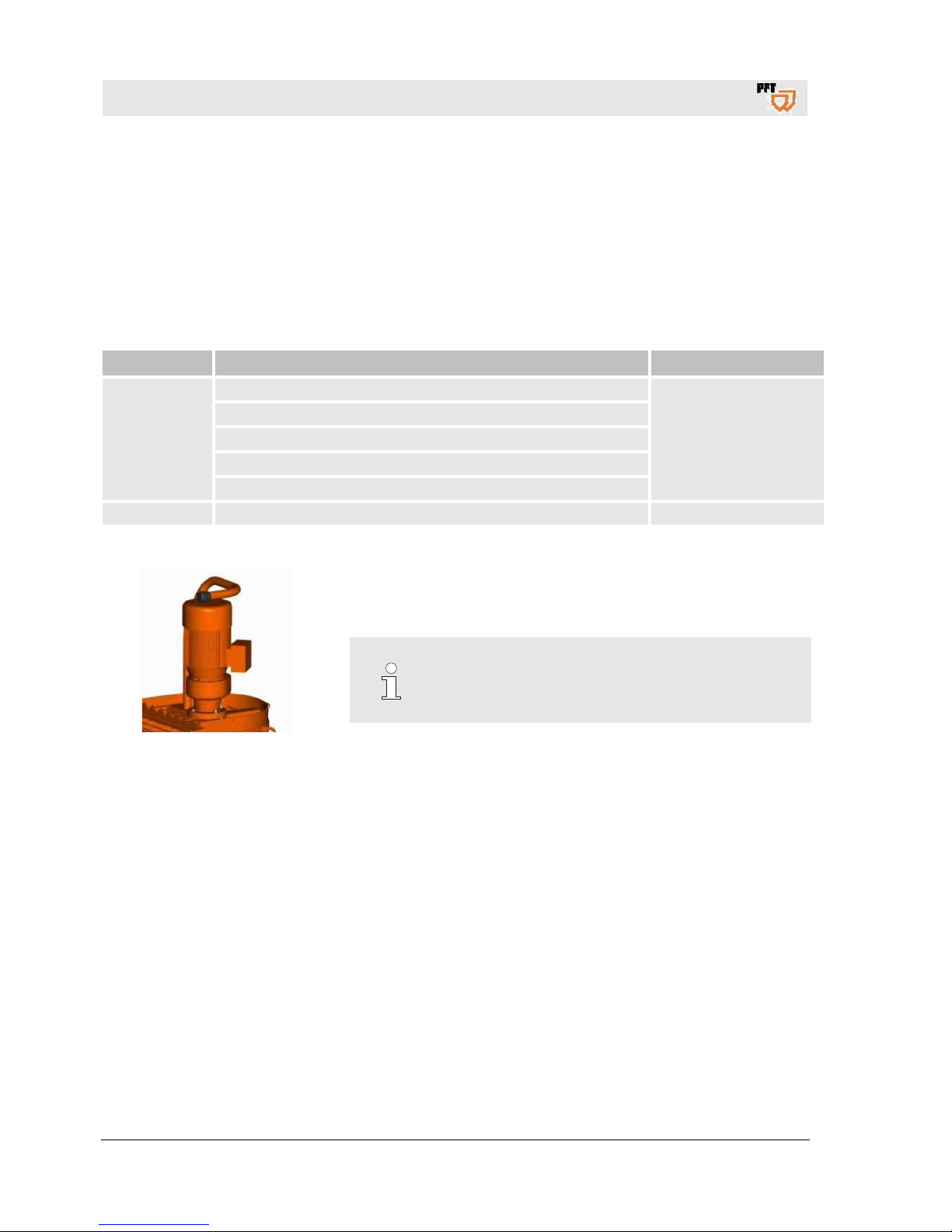
38.4 Gear motor
Fig. 61: Gear motor
NOTE!
The gear motor is filled as standard with 0.9 litres of
lubricating oil ISO VG 220 that has to be changed all
1000 hours, however all 3 years at the latest.
Page 43
Mixing pump BOLERO 230V, 2,2kW Overview - Operation - Spare parts lists
Maintenance
2019-01-15
43
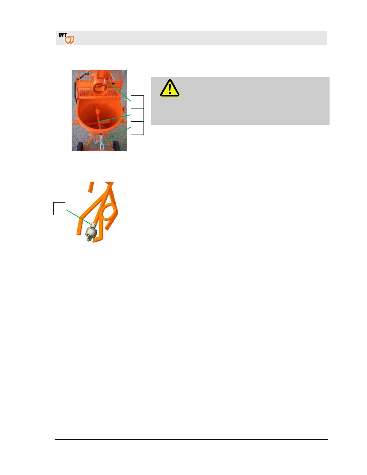
38.5 Remove agitator
Fig. 62: Remove agitator
DANGER!
Overpressure on the machine!
When opening machine parts they can open in an
uncontrolled manner and injure the operator.
– Open the mortar hoses only when the pressure has
dropped to "0 bar".
1. Open quick closure (1).
2. Flip open gear motor with protective grille (2).
3. Remove agitator (3).
38.6 Lubricate freewheel
Fig. 63: Lubricate freewheel
1. Unscrew the locking screw (1) at the freewheel.
2. Place the grease gun at the greasing nipple and lubricate until clean
grease can be seen at the freewheel (Lithium-based multi-purpose
grease).
3. Screw in locking screw at freewheel.
4. Check the fit of the freewheel for contamination.
5. Insert agitator.
6. Align driver and agitator and close gear motor with protective grille.
38.7 Measures after effected maintenance
After finishing the maintenance works and prior to switching on the
machine, the following steps have to be carried out:
1. Check all previously loosened screw connections for secure fit.
2. Check if all previously removed safety systems and covers are
properly reinstalled.
3. Ensure that all used tools, materials and other equipments were
removed from the work area.
4. Clean the work area and remove any spilled materials such as
liquids, processing material or similar.
5. Ensure that all safety systems of the installation work perfectly.
2
3
1
1
Page 44
Mixing pump BOLERO 230V, 2,2kW Overview - Operation - Spare parts lists
Disassembly
44
2019-01-15
39 Disassembly
After the useful service life has terminated, the device has to be
dismantled and disposed of in an environmentally-friendly manner.
39.1 Safety
The disassembly must be carried out only by specially trained
skilled personnel.
Works at the electrical system must be carried out by qualified
electricians only.
Basic information
WARNING!
Risk of injury in case of improper disassembly!
Stored residual energies, sharp components,
points or edges at and inside the device or at the
required tools might cause injuries.
Therefore:
– Prior to starting the works ensure that there is
sufficient space.
– Carefully handle components with sharp edges.
– Ensure order and cleanliness at the working
place! Loosely stacked components or
components lying about and tools are accident
sources.
– Dismantle components correctly. Pay attention
to partly high dead weight of the components. If
required use lifting equipment.
– Secure components that they do not fall down
or fall over.
– In case of doubt consult the manufacturer.
Electrical system
DANGER!
Danger to life from electric current!
There is danger to life in contact with live parts.
Activated electrical components can carry out
uncontrolled movements and cause serious
injuries.
Therefore:
– Prior to beginning the disassembly switch off
the power supply and finally disconnect it.
Page 45

Mixing pump BOLERO 230V, 2,2kW Overview - Operation - Spare parts lists
Spare parts list pump shaft
2019-01-15
45
39.2 Disassembly
Clean the device for phasing out and disassemble under
observance of applicable health and safety rules as well as
environmental regulations.
Prior to starting the disassembly:
Switch off device and secure against restarting.
Physically separate the complete energy supply to the device,
discharge stored residual energies.
Remove operating supplies as well as remaining processing
materials and dispose of in an environmentally-friendly way.
39.3 Disposal
If not agreement for the recovery or the disposal was made,
recycle the disassembled components:
Scrap metals.
Recycle plastic elements.
Dispose of remaining components separately according to their
material characteristics.
CAUTION!
Environmental damage in case of incorrect
disposal!
Waste from electronic and electrical equipment,
electronic components, lubricants and other
auxiliary materials are subject to hazardous waste
treatment and must be disposed of by specialised
companies only!
The local authority or special waste management operators can
supply information on environmentally-friendly disposal.
40 Spare parts list pump shaft
POS Qty Article no. Article description
1 1 00 23 28 90 Pump shaft BOLERO galvanised
Field of application pump shaft: For all pumpable wet products and pasty materials that do not
require to be mixed.
Place the pump shaft with the elongated hole facing downwards.
Page 46

Mixing pump BOLERO 230V, 2,2kW Overview - Operation - Spare parts lists
Index
46
2019-01-15
41 Index
A
Accessories .................................................... 8, 15
Agitator ............................................................... 13
Apply material .................................................... 27
Assembly ........................................................... 12
C
Causes for blockages ........................................ 34
Clean he material container ............................... 38
Clean material container .................................... 39
Clean mortar hose ............................................. 37
Clean Zargomat and gluing gun ........................ 38
Cleaning ............................................................. 41
Cleaning BOLERO ............................................. 36
Cleaning the pump ............................................. 35
Close quick closure during transport ................. 18
Closing the motor tilt flange ............................... 17
Connect mortar hoses ....................................... 24
Connect remote control ..................................... 26
Connect Zargomat and gluing gun .................... 25
Connection ......................................................... 15
Connection mortar hose .................................... 15
Connection of power supply .............................. 22
Control cabinet ................................................... 14
Conveying stationary / clogging ......................... 33
D
Description of assemblies .................................. 13
Dimension sheet ................................................ 11
Disassembly ................................................. 44, 45
Discharging mortar pressure ............................. 30
Disposal ............................................................. 45
Division .................................................................7
E
Earlier damage to the mortar hose .................... 34
EC Declaration of Conformity ...............................5
Emergency OFF switch ..................................... 29
End of shift / Cleaning ........................................ 36
Examination ......................................................... 6
Examination by machine operator ....................... 6
F
Fault displays ..................................................... 31
Faults ................................................................. 31
Fill machine with factory prepared dry material . 25
Fill water into the material container .................. 22
Flowability / Flow characteristics ........................ 16
Functional description ........................................ 16
G
Gear motor ......................................................... 42
Gear motor with protective grille ........................ 13
General information ............................................. 7
General information ............................................. 9
H
Hazardous dusts ................................................ 26
I
Index .................................................................. 46
Interruption of work ............................................ 28
K
Keep the manual for future reference .................. 7
L
Lubricate freewheel ............................................ 43
M
Main switch at position ....................................... 29
Maintenance ....................................................... 40
Maintenance plan ............................................... 42
Material .............................................................. 16
Material container with control cabinet .............. 13
Measures after effected maintenance................ 43
Measures to be taken in the event of a power
failure .............................................................. 29
Mortar hoses ...................................................... 24
Mortar pressure gauge ................................. 16, 23
Motor connecting cable for pump motor ............ 22
Page 47

Mixing pump BOLERO 230V, 2,2kW Overview - Operation - Spare parts lists
Index
2019-01-15
47
N
Name plate ......................................................... 11
O
Open protective grille .......................................... 39
Operating conditions ........................................... 10
Operating manual ................................................. 7
Operating modes ................................................ 14
Operation ............................................................ 20
Overview ............................................................. 12
P
Packaging ........................................................... 20
Packing ............................................................... 17
Periodic inspection ............................................... 6
Personal protective equipment ........................... 32
Personal protective equipment ........................... 20
Power connection ................................................. 9
Power values ...................................................... 10
Preparation ......................................................... 21
Prepare mortar hoses ......................................... 24
Putting the machine into operation ..................... 25
Q
Quality Control sticker ........................................ 11
R
Reaction in the event of faults ............................ 31
Recommended accessories ............................... 15
Remote control cable .......................................... 15
Removal of clogging in hoses ............................ 34
Remove agitator ................................................. 43
Removing the connection cable ......................... 38
Re-tighten pump ................................................. 28
Risk of frost ......................................................... 40
Risk of injury to due overpressure ...................... 35
S
Safety ............................................................ 40, 44
Safety instructions for transport ..........................17
Safety rules .........................................................16
Saftey ..................................................................20
Safty ....................................................................32
Selector switch mixing function in conveying
breaks ..............................................................14
Selector switch pump motor ...............................14
Signs for clogging ...............................................33
Sound power level ..............................................10
Spare parts list pump shaft .................................45
Spare parts lists .................................................... 8
Start off machine .................................................25
Stopping in case of emergency ..........................29
Storage ...............................................................17
Switch machine on again ....................................28
Switching off in an emergency ............................29
Switching off the energy supplies .......................36
Switching off the machine ...................................27
Switching on .......................................................27
Switching on the machine ...................................38
Switching on the machine again after a power
failure ...............................................................30
T
Table of faults .....................................................32
Technical data ...................................................... 9
Trail run ...............................................................23
Transport.............................................................17
Transport by crane ..............................................19
Transport checklist ..............................................18
Transport in individual parts................................18
Transportation of operational machines .............19
V
Vibrations ............................................................10
W
Work on troubleshooting .....................................31
Page 48

Mixing pump BOLERO 230V, 2,2kW Overview - Operation - Spare parts lists
48
2019-01-15
PFT – THE FLOW OF PRODUCTIVITY
Knauf PFT GmbH & Co. KG
Postfach 60 97343 Iphofen
Einersheimer Straße 53 97346 Iphofen
Germany
Telephone +49 9323 31-760
Fax +49 9323 31-770
Technical hotline +49 9323 31-1818
www.pft.net
 Loading...