


OPERATING INSTRUCTIONS
ACP 15
Dry compact Multi-stage Roots pump
EN
Translation of the original instructions

Table of contents
Table of contents
1 About this manual. . . . . . . . . . . . . . . . . . . . . . . . . . . . . . . . . . . . . . . . . . . . . . . 4
2 Safety . . . . . . . . . . . . . . . . . . . . . . . . . . . . . . . . . . . . . . . . . . . . . . . . . . . . . . . . . 7
3 Transport and storage. . . . . . . . . . . . . . . . . . . . . . . . . . . . . . . . . . . . . . . . . . . 10
4 Product description. . . . . . . . . . . . . . . . . . . . . . . . . . . . . . . . . . . . . . . . . . . . . 12
5 Installation . . . . . . . . . . . . . . . . . . . . . . . . . . . . . . . . . . . . . . . . . . . . . . . . . . . . 14
6 Operation . . . . . . . . . . . . . . . . . . . . . . . . . . . . . . . . . . . . . . . . . . . . . . . . . . . . . 23
7 Maintenance. . . . . . . . . . . . . . . . . . . . . . . . . . . . . . . . . . . . . . . . . . . . . . . . . . . 31
1.1 Validity. . . . . . . . . . . . . . . . . . . . . . . . . . . . . . . . . . . . . . . . . . . . . . . . . . . . . 4
1.1.1 Applicable documents . . . . . . . . . . . . . . . . . . . . . . . . . . . . . . . . . . . 4
1.2 Conventions . . . . . . . . . . . . . . . . . . . . . . . . . . . . . . . . . . . . . . . . . . . . . . . . 4
1.2.1 Safety instructions . . . . . . . . . . . . . . . . . . . . . . . . . . . . . . . . . . . . . . 4
1.2.2 Pictographs . . . . . . . . . . . . . . . . . . . . . . . . . . . . . . . . . . . . . . . . . . . 5
1.2.3 Instructions/Abbreviations used . . . . . . . . . . . . . . . . . . . . . . . . . . . 5
1.2.4 Labels . . . . . . . . . . . . . . . . . . . . . . . . . . . . . . . . . . . . . . . . . . . . . . . 5
2.1 Safety precautions . . . . . . . . . . . . . . . . . . . . . . . . . . . . . . . . . . . . . . . . . . . 7
2.2 Protective equipment . . . . . . . . . . . . . . . . . . . . . . . . . . . . . . . . . . . . . . . . . 8
2.3 Proper use . . . . . . . . . . . . . . . . . . . . . . . . . . . . . . . . . . . . . . . . . . . . . . . . . 9
2.4 Improper use. . . . . . . . . . . . . . . . . . . . . . . . . . . . . . . . . . . . . . . . . . . . . . . . 9
3.1 Transport. . . . . . . . . . . . . . . . . . . . . . . . . . . . . . . . . . . . . . . . . . . . . . . . . . 10
3.2 Storage . . . . . . . . . . . . . . . . . . . . . . . . . . . . . . . . . . . . . . . . . . . . . . . . . . . 11
4.1 Product identification. . . . . . . . . . . . . . . . . . . . . . . . . . . . . . . . . . . . . . . . . 12
4.1.1 Scope of delivery. . . . . . . . . . . . . . . . . . . . . . . . . . . . . . . . . . . . . . 12
4.1.2 Differences between the pump versions . . . . . . . . . . . . . . . . . . . . 12
4.2 Man/machine interfaces . . . . . . . . . . . . . . . . . . . . . . . . . . . . . . . . . . . . . . 13
5.1 Set-up . . . . . . . . . . . . . . . . . . . . . . . . . . . . . . . . . . . . . . . . . . . . . . . . . . . . 14
5.2 Connection to the pumping line . . . . . . . . . . . . . . . . . . . . . . . . . . . . . . . . 14
5.2.1 Connection at pump inlet . . . . . . . . . . . . . . . . . . . . . . . . . . . . . . . 15
5.2.2 Connection at pump exhaust . . . . . . . . . . . . . . . . . . . . . . . . . . . . 15
5.2.3 Connecting the purge circuit . . . . . . . . . . . . . . . . . . . . . . . . . . . . . 15
5.3 Leak test . . . . . . . . . . . . . . . . . . . . . . . . . . . . . . . . . . . . . . . . . . . . . . . . . . 16
5.4 Electrical connection . . . . . . . . . . . . . . . . . . . . . . . . . . . . . . . . . . . . . . . . . 16
5.4.1 Customer electrical installation protection. . . . . . . . . . . . . . . . . . . 17
5.4.2 Connection to the mains power supply . . . . . . . . . . . . . . . . . . . . . 18
5.5 Remote connector wiring . . . . . . . . . . . . . . . . . . . . . . . . . . . . . . . . . . . . . 18
5.5.1 Wiring of digital inputs . . . . . . . . . . . . . . . . . . . . . . . . . . . . . . . . . . 18
5.5.2 Setting of the rotation speed . . . . . . . . . . . . . . . . . . . . . . . . . . . . . 19
5.5.3 Wiring of the digital outputs . . . . . . . . . . . . . . . . . . . . . . . . . . . . . . 19
5.6 RS-485 serial link wiring . . . . . . . . . . . . . . . . . . . . . . . . . . . . . . . . . . . . . . 20
5.6.1 Connections . . . . . . . . . . . . . . . . . . . . . . . . . . . . . . . . . . . . . . . . . 20
5.6.2 Setting . . . . . . . . . . . . . . . . . . . . . . . . . . . . . . . . . . . . . . . . . . . . . . 21
5.6.3 Command list . . . . . . . . . . . . . . . . . . . . . . . . . . . . . . . . . . . . . . . . 22
6.1 Prerequisites to use . . . . . . . . . . . . . . . . . . . . . . . . . . . . . . . . . . . . . . . . . 23
6.2 Matrix gas/applications . . . . . . . . . . . . . . . . . . . . . . . . . . . . . . . . . . . . . . . 25
6.3 Different control modes. . . . . . . . . . . . . . . . . . . . . . . . . . . . . . . . . . . . . . . 26
6.3.1 Local mode operation . . . . . . . . . . . . . . . . . . . . . . . . . . . . . . . . . . 26
6.3.2 Remote mode operation . . . . . . . . . . . . . . . . . . . . . . . . . . . . . . . . 27
6.3.3 RS-485 serial link operation . . . . . . . . . . . . . . . . . . . . . . . . . . . . . 28
6.3.4 Operation monitoring. . . . . . . . . . . . . . . . . . . . . . . . . . . . . . . . . . . 29
6.4 Gas ballast operation . . . . . . . . . . . . . . . . . . . . . . . . . . . . . . . . . . . . . . . . 29
6.5 Purge operation . . . . . . . . . . . . . . . . . . . . . . . . . . . . . . . . . . . . . . . . . . . . 30
7.1 Safety and maintenance information . . . . . . . . . . . . . . . . . . . . . . . . . . . . 31
7.1.1 How to contact us . . . . . . . . . . . . . . . . . . . . . . . . . . . . . . . . . . . . . 32
7.2 Maintenance frequency. . . . . . . . . . . . . . . . . . . . . . . . . . . . . . . . . . . . . . . 32
7.3 Maintenance on the customer’s site . . . . . . . . . . . . . . . . . . . . . . . . . . . . . 32
7.4 Standard repair exchange. . . . . . . . . . . . . . . . . . . . . . . . . . . . . . . . . . . . . 33
2

Table of contents
7.4.1 Disconnecting the pump from the installation . . . . . . . . . . . . . . . . 33
7.4.2 Conditioning the pump for shipping. . . . . . . . . . . . . . . . . . . . . . . . 33
8 Decommissioning . . . . . . . . . . . . . . . . . . . . . . . . . . . . . . . . . . . . . . . . . . . . . . 34
8.1 Shutting down for longer periods . . . . . . . . . . . . . . . . . . . . . . . . . . . . . . . 34
8.2 Re-starting . . . . . . . . . . . . . . . . . . . . . . . . . . . . . . . . . . . . . . . . . . . . . . . . 34
8.3 Disposal . . . . . . . . . . . . . . . . . . . . . . . . . . . . . . . . . . . . . . . . . . . . . . . . . . 34
9 Malfunctions . . . . . . . . . . . . . . . . . . . . . . . . . . . . . . . . . . . . . . . . . . . . . . . . . . 35
9.1 Trouble at pump start-up. . . . . . . . . . . . . . . . . . . . . . . . . . . . . . . . . . . . . . 35
9.2 The pump runs incorrectly . . . . . . . . . . . . . . . . . . . . . . . . . . . . . . . . . . . . 35
10 Service . . . . . . . . . . . . . . . . . . . . . . . . . . . . . . . . . . . . . . . . . . . . . . . . . . . . . . . 36
11 Accessories . . . . . . . . . . . . . . . . . . . . . . . . . . . . . . . . . . . . . . . . . . . . . . . . . . . 37
12 Technical data and dimensions . . . . . . . . . . . . . . . . . . . . . . . . . . . . . . . . . . . 38
12.1 General . . . . . . . . . . . . . . . . . . . . . . . . . . . . . . . . . . . . . . . . . . . . . . . . . . . 38
12.2 Technical data. . . . . . . . . . . . . . . . . . . . . . . . . . . . . . . . . . . . . . . . . . . . . . 38
12.3 Facilities characteristics . . . . . . . . . . . . . . . . . . . . . . . . . . . . . . . . . . . . . . 39
12.3.1 Environmental conditions . . . . . . . . . . . . . . . . . . . . . . . . . . . . . . . 39
12.3.2 Nitrogen characteristics. . . . . . . . . . . . . . . . . . . . . . . . . . . . . . . . . 39
12.3.3 Electrical characteristics . . . . . . . . . . . . . . . . . . . . . . . . . . . . . . . . 39
12.4 Dimensions . . . . . . . . . . . . . . . . . . . . . . . . . . . . . . . . . . . . . . . . . . . . . . . . 40
12.5 Weight distribution and seismic brackets . . . . . . . . . . . . . . . . . . . . . . . . . 41
ETL Mark . . . . . . . . . . . . . . . . . . . . . . . . . . . . . . . . . . . . . . . . . . . . . . . . . . . . . 42
Declaration of conformity. . . . . . . . . . . . . . . . . . . . . . . . . . . . . . . . . . . . . . . . 43
3

About this manual
1 About this manual
1.1 Validity
This operating manual is for customers of Pfeiffer Vacuum. It describes the functioning
of the designated product and provides the most important information for safe use of
the unit. The description follows applicable EU guidelines. All information provided in this
operating manual refers to the current state of the product's development. The documentation remains valid as long as the customer does not make any changes to the product.
Up-to-date operating instructions can also be downloaded from
www.pfeiffer-vacuum.com.
This document is a translation of the original French instructions.
This manual covers products with the following references:
Part number Model Description
V5SAXXXXXX
V5VSXXXXXX
V5GAXXXXXX
V5VGXXXXXX
ACP 15 Models for standard applications
ACP 15 G Models for applications with traces of corrosive gases
1.1.1 Applicable documents
Declaration of conformity included with this manual
UL/CSA compliant use (ETL mark) included with this manual
1.2 Conventions
1.2.1 Safety instructions
The safety instructions in Pfeiffer Vacuum operating instructions are the result of risk
evaluations and hazard analyses and are oriented on international certification standards as specified by UL, CSA, ANSI Z-535, SEMI S2, ISO 3864 and DIN 4844. In this
document, the following hazard levels and information are considered:
Imminent danger
Indicates an imminent hazardous situation that will result in death or serious injury.
Possibly imminent danger
Indicates an imminent hazardous situation that can result in death or serious injury.
DANGER
WARNING
CAUTION
Possibly imminent danger
Indicates an imminent hazardous situation that can result in minor or moderate injury.
NOTICE
Command or note
Command to perform an action or information about properties, the disregarding of
which may result in damage to the product.
4

1.2.2 Pictographs
P0385E4
AC Rating 110-230V 50/60Hz 15-10A
Frequency inverter serial n°
Référence
SEISMIC TIE DOWN
A 329 962 - 5
Prohibition of an action or activity in connection with a source of danger,
the disregarding of which may result in serious accidents
Warning of a displayed source of danger in connection with operation of
the unit or equipment
Command to perform an action or task associated with a source of danger, the disregarding of which may result in serious accidents
Important information about the product or this document
1.2.3 Instructions/Abbreviations used
About this manual
1.2.4 Labels
or Work instruction: you must perform an operation here.
I/O Pump Start/Stop
INLET Pump inlet connection
PUMP EXHAUST Pump exhaust connection
This label warns the user against possible risk of injury due to any hand contact with
hot surfaces.
It states that protective gloves should be used before performing any intervention.
This label informs the user, that moving parts present inside the pump could cause personal injury, like crushing or cutting.
The user must keep all body parts away from moving parts.
This label indicates that due to its heavy weight, the product should not be handled
manually,
but always through appropriate handling devices.
This label indicates that some of the internal parts are energized and could cause electrical shocks in case of contact.
It advises to disconnect the pump before any intervention or to properly lock-out and
tag-out the equipment breaker before any intervention on the pump.
This label indicates the voltage of the equipment in which the pump is to be connected.
This label indicates the location of the holes for seismic bracket installation.
5
About this manual
CAUTION
Use suitable power supply cord
for required voltage
Hot surface
Do not touch
See user’s manual
ATTENTION
Utiliser le câble d’alimentation
adapté pour la tension requise
Surface chaude
Ne pas toucher
Consulter les documents joints
1
2
3
4
5
6
7
7
6
6
1Weight Label
2 Heavy object label
3 Hot surface label
4 Hazardous voltage label
5 Presence of moving part label
6 Seismic down label
7 Mains voltage Label
This label indicates that the power supply must be switched off before connecting and/
or disconnecting the pump. Any person responsible for installation or operation of the
product must first refer to the operating manual.
This label warns the user against potential risks associated with the use of this product.
Any person responsible for installation or operation of the product must first refer to the
operating manual.
The installer must glue the following labels to the most appropriate and visible
place on the pump to warn the operator about potential hazards:
6

2Safety
2.1 Safety precautions
Obligation to inform
Any person responsible for installing, using or maintaining the product must first read
the security instructions in this operating manual and comply with them.
It is the operating customer’s responsibility to protect all operators against the dan-
gers associated with the product, with the media pumped and with the entire installation.
Installation and use of the accessories
The products can be fitted with special accessories. The installation, use and refurbishment of the connected accessories are described in detail in the respective manuals.
Only use original accessories.
Accessory part numbers: see Accessories.
Hazard associated with non-compliant electrical installation
Safe operation after installation is the operator’s responsibility.
Connect the product to an installation that is compliant with local safety standards.
Do not carry out any alterations or modifications to the product on your own initiative.
For specific questions, contact your service center.
Safety
WARNING
WARNING
Electric shock hazard in case of contact
When the product's mains switch is set at O, some internal components still have an
electrical charge.
Make sure that the mains connection is always visible and accessible so that it can
be unplugged at any time.
Disconnect the power cable from all power sources before starting any work on the
product.
WARNING
Danger due to lack of lock out/tag out (LO/TO) electrical device.
In order to properly secure the pump for installation and/or maintenance, it is required
to lock out/tag out the pump properly in accordance with OSHA requirement
29 CFR.1910.147.
WARNING
Other located hazardous energies
Electrical circuit and other pressurized circuits as nitrogen are potential hazards:
Always lock out these energy sources before working on the product.
7

Safety
WARNING
Risk associated with process gases
The user and/or integrator of the product is/are fully responsible for the operational safety conditions of the equipment. The manufacturer has no control over the types of gases
this pump is exposed to. Frequently process gases are toxic, flammable, corrosive, explosive and/or otherwise reactive. It is the user and/or the integrator's responsibility to
follow the necessary safety requirements. Toxic gases can cause serious injury or
death. Operators and users must:
Take the appropriate safety recommendations to prevent injury. Consult the respon-
sible department for instructions and safety information.
Hazardous gases from the pump can cause serious injury or death. Regula-
tions require to connect the pump’s exhaust to a facility hazardous gas exhaust system which incorporates appropriate filters, scrubbers, etc. This system
must meet all air and water regulations.
Check that the pump is correctly connected to the equipment (see Installation).
Contact the service center for further information.
The potential risks with an air cooled, dry multi-stage Roots pump involve electricity, the
chemical processes, hot surfaces, the pressurized nitrogen device.
● Only qualified personnel trained in safety rules (EMC, electrical safety, chemical pollution) may carry out the installation and maintenance described in this manual. Our
service centers can provide the necessary training.
● Do not remove the blanking plates sealing the inlet and exhaust ports if the product is
not connected to the pumping line.
● Do not operate the product unless the inlet and exhaust are connected to a vacuum
and exhaust pumping line.
● Do not expose any part of the human body to the vacuum.
● Comply with all safety and risk prevention instructions in accordance with local safety
standards.
● Regularly check compliance with all precautionary measures.
● Do not turn on the product if the covers are not in place.
2.2 Protective equipment
In some situations, personal protective equipment must be worn when handling the vacuum pump and its components. The owner must provide operators with the necessary
equipment. This equipment must be checked regularly and used in accordance with the
supplier's recommendations.
Health risk relating to contact with toxic materials
The vacuum pump, pumping line components, and operating media may be contaminated with toxic, corrosive, reactive, or radioactive materials, depending on the process.
Wear appropriated safety equipment when pump is disconnected for maintenance,
or re-installed, and also for oil filling and draining.
Risk of injury due to hot surfaces
For the operator's safety, the products are designed to avoid thermal risk. However, specific operating conditions may exist that require extra caution from users due to the high
temperatures (external surfaces > 70°C on the exhaust pipe).
Let the part cool before working on the product.
If necessary wear protective gloves according to directive EN 420.
DANGER
WARNING
8

2.3 Proper use
kg
Safety
WARNING
Risk of injury due to falling objects
When transporting parts/items by hand, there is a danger of loads slipping and falling
down.
Carry small and medium-size parts/items with two hands.
Carry parts/items > 20 kg with a suitable lifting device.
Wear safety shoes with steel toe according to directive EN 347.
NOTICE
EC conformity
The manufacturer's declaration of conformity becomes invalid if the operator modifies
the original product or installs additional components.
Following installation into a plant and before commissioning, the operator must check
the entire system for compliance with the valid EU directives and reassess it accordingly.
● The vacuum pump may only be used to generate a vacuum while pumping gases.
● The product may be used in an industrial environment.
● The product may be used in a laboratory environment.
● The G version pump is compatible with traces of corrosive gases.
2.4 Improper use
Improper use will cause all claims for liability and warranties to be forfeited. Improper use
is defined as usage for purposes deviating from those mentioned above, especially:
● pumping of flammable and explosive mixtures
● pumping of corrosive gases (exception: pumps in G version)
● pumping of liquids
● pumping of dusts
● use of the vacuum pump to generate pressure
● operation in potentially explosive areas
● use of accessories or spare parts, which are not named in this manual
The product is not designed to carry people or loads and is not for use as a seat, stepladder or any other similar purpose.
9

Transport and storage
3 Transport and storage
Upon delivery, check that the product has not been damaged during transport. If the
product is damaged, contact the carrier and notify the manufacturer. In all situations we
recommend:
Keeping the product in its original packaging so it stays as clean as it was when dis-
patched by us. Only unpack the product once it has arrived at the location where it will
be used.
Keeping the packaging (recyclable materials) in case the product needs to be trans-
ported or stored.
Keeping the blanking plates in place on the inlet, exhaust and purge ports while the
product is not connected to the pumping line.
3.1 Transport
Risk of injury associated with heavy loads
Given the weight of the product, it should be removed from its packaging only by personnel qualified and trained in handling heavy materials.
Use the lifting rings and devices provided with the product.
The manufacturer cannot be held liable for the consequences of using lifting devices
other than those provided.
WARNING
WARNING
Risk of tilting
Even though compliance with EEC safety rules is guaranteed, all necessary precautions
should be taken when moving, installing and operating the product.
Do not place the product on an inclined plane.
Place it on a flat, hard floor.
Do not push the product sideways.
To lift the product:
Use a lifting device suitable for the product's weight.
Use a lifting sling with a single arm that can withstand a
load > 23 kg.
A wheel kit is available as accessory: fitted over the frame,
it facilitates the displacement of the pump over short distanc-
es (see 11) and (see 12.4).
10

3.2 Storage
Storage of a new pump If the new pump is going to be put into storage:
Keep the pump wrapped in its protective film.
It is absolutely necessary to leave the inlet, the exhaust and purge blanking plates
in place.
Store the pump according to storage temperatures (see 12.3.1).
Store the pump in a clean and dry area, for a maximum period of 1 year.
For longer storage, we recommend operating the pump regularly at least once a year:
factors such as temperature, degree of humidity, salt air, ... may cause the deterioration
of the pump components. Proceed as follows:
Let the pump to run:
– for 30 minutes with gas ballast opened or by injecting a dry inert gas into the pump
(G version),
– then, for 30 minutes at ultimate pressure (inlet, gas ballast and purge ports closed).
Stop the pump.
Seal the pump inlet, exhaust and purge ports with included accessories.
Repeat this at least once a year.
For a storage period of over 4 years, the pump must be revised before any start up. Re-
turn it to a service center according to the product return Service procedure (see 10).
Storage after use Stop the pump according to pump shut-down procedure (see 6.3.1), (see 6.3.2) or
(see 6.3.3).
Disconnect the pump from the installation (see 7.4.1).
Seal the pump inlet, exhaust and purge ports with included accessories.
Store the pump in a clean, dry, non-polluted area for a maximum of 6 months accord-
ing to the storage temperatures (see 12.3.1).
Transport and storage
For longer storage, we recommend operating the pump every 6 months. Proceed as fol-
lows:
Let the pump to run:
– for 30 minutes with gas ballast opened or by injecting a dry inert gas into the pump
(G version),
– then, for 30 minutes at ultimate pressure (inlet, gas ballast and purge ports closed).
Stop the pump.
Seal the pump inlet, exhaust and purge ports with included accessories.
Repeat this every 6 months.
For a storage period of over 2 years, the pump must be revised before any start up. Re-
turn it to a service center according to the product return Service procedure (see 10).
11

Product description
4 Product description
4.1 Product identification
To correctly identify the product when communicating with Pfeiffer Vacuum, always have
the information from the rating plate available.
V6SATSFEMF
2015
AC668838
Max. pres:1013 mBar
Fig. 1: Product identification on the rating plate
4.1.1 Scope of delivery
● 1 vacuum pump
● 1 remote cover plug for remote connector (connected to the pump)
● 1 operating instructions
● 1 sheet of multilingual labels
and depending on the ordering guide, the following components are present:
1 main power cable
4.1.2 Differences between the pump versions
The multi-stage Roots pump technology of the ACP series meets the requirements of
applications where clean and dry vacuum is needed.
Standard version The SD version is designed for applications that require pumping of clean (dust-free)
and non-corrosive gases. Standard pumps are equipped with a gas ballast device to improve pumping of light gases and avoid vapor condensation inside the pump.
G version The G version pump is compatible with traces of corrosive gases. Three purge gas jets
protect low and high pressure bearings and dilute trace amounts of corrosive gases.
Please contact Pfeiffer Vacuum to obtain more detailed information according to the applications.
4800 rpm
12
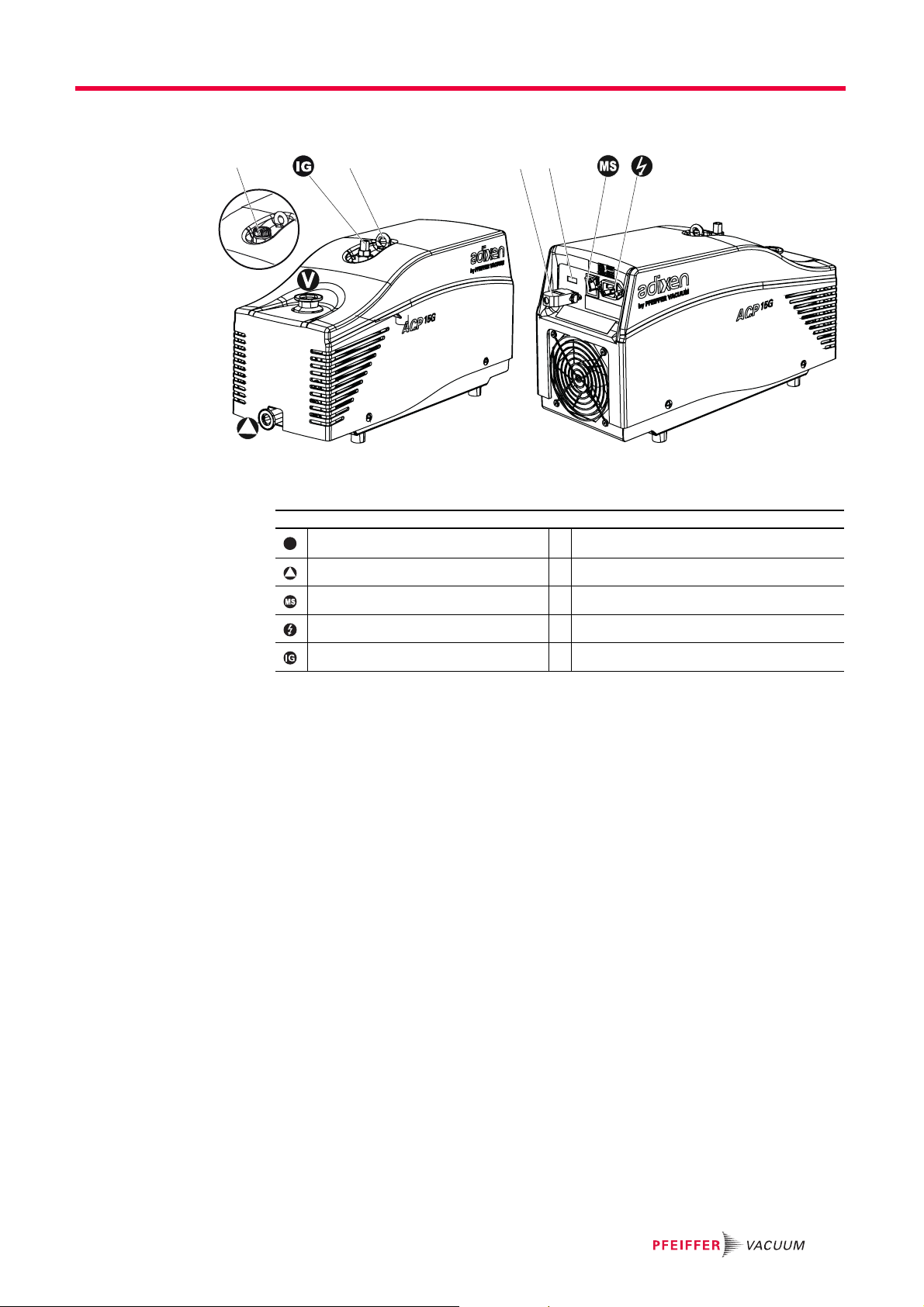
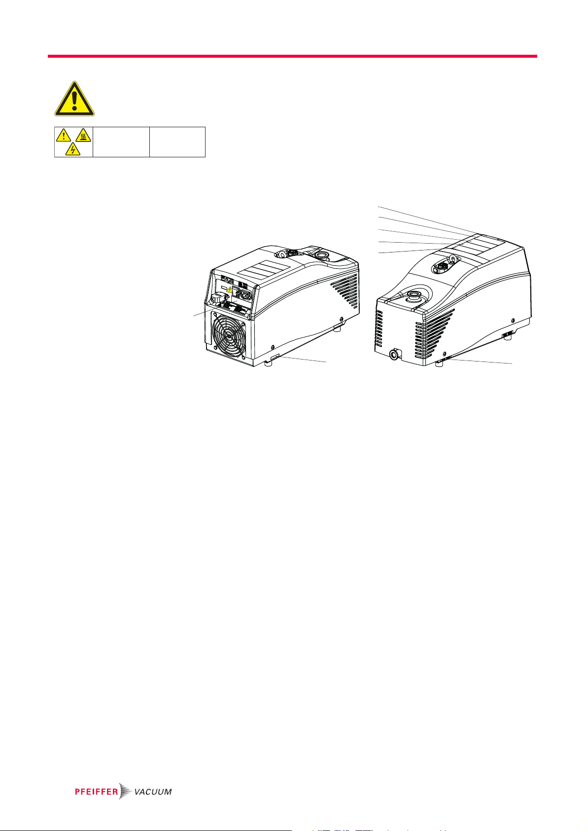
4.2 Man/machine interfaces
1342
V
Fig. 2: ACP 15 with single-phase frequency converter
Pump inlet 1 Gas ballast (SD version)
Product description
Pump exhaust 2 Hoisting ring
I/O mains switch 3 Remote connector and RS-485 connector
Power supply 4 Hour meter
Inert gas purge connection (G version)
13
Installation
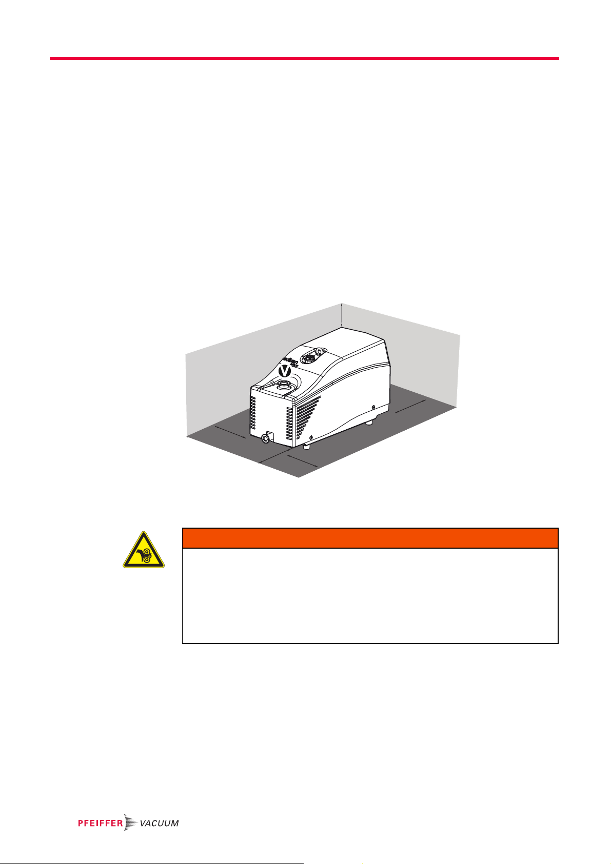
80 mm
mini
80 mm
mini
80 mm
mini
80 mm
mini
80 mm
mini
5 Installation
5.1 Set-up
Ventilation To guarantee the characteristics and performances of the pump within the boundaries of
The pump must be operated in the horizontal position in support on its feet, with the
pumping axis vertical and the inlet opening upwards.
Determine where the pump will be placed.
Use the handling devices to position the pump in the desired location, lift the pump
using hoisting rings (see 3.1).
Install the pump so that the I/O mains switch is accessible by the operator.
the operating conditions:
Check that the air circulation grids are not blocked.
Take away the pump of the fixed walls, at least the value indicated on the diagram be-
low.
5.2 Connection to the pumping line
Risk of crushing or cutting related to the rotating parts
Do not expose any part of the human body to the vacuum. The product is supplied with
the inlet and exhaust sealed.
Remove these blanking plates when you are ready to connect the product to your
vacuum system.
Do not operate the product unless the inlet and exhaust are connected to a vacuum
and exhaust pumping line.
Use accessories on the inlet and exhaust lines whose materials and sealing proper-
ties are compatible with gases being used.
Provide in the pumping line, accessories to isolate the pump from the vacuum and ex-
haust line, to make the maintenance easier (inlet and exhaust isolation valves, purges,…).
Remove the blanking plates blocking the inlet and exhaust ports.
Keep the blanking plates, screws and washers for reuse when transporting the pump.
Ensure that no screws, washers or other objects are dropped into the pump inlet.
Fit flexible flanged bellows in the pumping line to reduce the transmission of vibra-
tions.
14
WARNING

The O-rings located under the blanking plates are compatible with standard applications.
Other types of connection accessories are available in the product catalogue. The inlet
and exhaust connections must not cause stress that could lead to leaks in the pumping
line.
5.2.1 Connection at pump inlet
Limit of operation
Make sure that the parts or chambers connected to the inlet of our products withstand
a negative pressure of 1·10
When the pump stops, the pressure rises at the inlet. This rise depends on the
inlet volume.
If necessary, install an isolation valve on the inlet which closes when the pump stops.
The product is not designed to withstand loads on its inlet flange which may compromise
stability.
NOTICE
3
hPa in relation to atmospheric pressure.
NOTICE
Installation
Mechanically attach the vacuum chamber separately from the pump.
It may be necessary to install a filter on the inlet (particulate filter or (see 11) condens-
ables filter).
To improve pumping speed, the pumping line must be as short as possible and its internal diameter must not be less than the pump inlet flange.
Use only dry parts and clean, grease-free, dust-free pipelines.
5.2.2 Connection at pump exhaust
Limit of operation
Ensure that all components in the exhaust pipeline have maximum pressure rating
which is greater than the highest pressure that can be generated in your system.
G version
Health risk in case of contact with toxic substances
Exhaust of corrosive, reactive, flammable, pyrophoric or oxidizing process gases may
result in severe injury or death.
Always connect the pump exhaust to an exhaust extraction system.
NOTICE
DANGER
5.2.3 Connecting the purge circuit
The gas purge consists of injecting an inert gas into the pump.
In this manual, the inert gas will be called 'nitrogen', as it is the most commonly used gas.
For more information about the type of purge gas, contact your service center Pfeiffer
Vacuum.
15

Installation
DANGER
Risk of explosion
If pyrophoric materials above the LEL (lower explosive limit) are sent to the pump, the
nitrogen supply must make it possible to dilute this concentration.
Ensure there is a sufficient flow of nitrogen to lower the concentration below the LEL.
Provide in addition an interlock to ensure that gas flow towards the pump is stopped
when nitrogen is lost.
NOTICE
Risk of nitrogen supply failure
If loss of purge flow creates a significant risk for the process:
Control the nitrogen supply using an external system able to take over in case of fail-
ure.
G version A gas purge circuit protects the low and high pressure bearings and dilutes trace
amounts of corrosive gases.
Connect the inert gas pipe to the 1/4 BSPT connector provided for this purpose (flex-
ible or rigid pipe supplied by the customer).
Install as close as possible from pump gas port, an isolation valve on the inert gas
pipe, to allow pump performance recovering when the gas supply is not used (see
12.2).
Inject inert gas purge with maximum relative pressure of 300 hPa (see 12.2).
A filtered dry nitrogen supply with the characteristics defined is required for opti-
mum performance (see 12.3.2).
5.3 Leak test
Leak-tightness of the equipment
It is the user's responsibility to ensure this level of leak tightness is maintained, especially when dangerous gases are pumped. The operator must maintain this level of tightness, particularly when pumping dangerous gases. Proceed as follows:
Perform a leak test on the entire pumping line after installation.
Carry out regular checks to ensure that there are no traces of the gases pumped in
the surrounding environment and that no air is entering the pumping line while the
pump is running.
For more information concerning leak tests, please contact your service center.
5.4 Electrical connection
Electric shock hazard in case of contact
When the product's mains switch is set at O, some internal components still have an
electrical charge.
Make sure that the mains connection is always visible and accessible so that it can
be unplugged at any time.
Disconnect the power cable from all power sources before starting any work on the
product.
WARNING
WARNING
16

Installation
WARNING
Risk of electromagnetic disturbance
The product’s EMC behavior is guaranteed only if the relevant EMC standards are followed during installation.
Use shielded cables and connections for the interfaces in interference-prone environ-
ments.
WARNING
Hazard associated with non-compliant electrical installation
Safe operation after installation is the operator’s responsibility.
Connect the product to an installation that is compliant with local safety standards.
Do not carry out any alterations or modifications to the product on your own initiative.
For specific questions, contact your service center.
Electrical safety The pump is equipped with an I/O mains switch that isolates the product from power line
when it is on O position.
The pump is equipped with a frequency converter in compliance with EC standards that
allows pump running in high and low voltages (see 5.4.1). The frequency converter is
protected against short-circuits from power line. Once this safety activated, power is
switched off and the pump is put in a safe condition. To restart the pump, you must:
switch power off, mains switch to O position,
delete the origin of the fault, then,
wait for about 15 seconds,
then, switch power on , to I position.
The pump is equipped with thermal sensors that prevent pump start-up at certain tem-
peratures (see 6.1).
5.4.1 Customer electrical installation protection
The pump is connected to the mains with the delivered mains power cable. The earth
connection (frequency converter, cover, pump) is made via the power cable connected
to a compliant electrical installation.
When the mains power cable is provided by the customer:
Use an EEC cable in compliance with IEC 60227 and IEC 60245 standards with the
following characteristics:
– heatproof (because it can come into contact with hot surfaces),
– with conducting wire section suitable with the voltage (see 12.3.3),
– and which one of the wire ensures grounding of the pump.
Installation protection with circuit breaker
The user must supply the pump from facilities equipped with main circuit breaker, curve
D (IEC 60947-2), in accordance with local regulations and with at least a 10 kA short circuit cut-off capacity. This protection device should be in close proximity to the pump (no
further than 7 m) within line of sight of the pump.
This circuit breaker supply and wiring is a customer’s responsibility: main circuit breaker
rating (see 12.3.3).
WARNING
Absence of emergency off
This pump is not equipped with an emergency off device EMO or a lock-out device. It is
designed to be integrated with the host tool equipment equipped with an emergency device. This EMO device must de-energize the pump when it is activated.
17

Installation
1567234
91015 14 13 12 11
8
S1
S3S4S5
Operation in local mode
There is no device to warn that the pump is operating in local mode.
Provide a device to warn about local mode operation when the pump is not integrat-
ed with equipment/host tool.
5.4.2 Connection to the mains power supply
Connect the mains power cable to the connector .
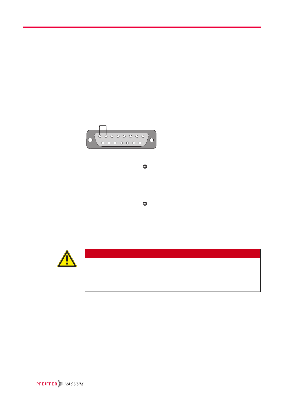
5.5 Remote connector wiring
Connection made via the Remote connector (Male 15-pin D-Sub) (see 4.2), allows:
– remote control of following functions: start, stop of the pump,
– setting of pump rotational speed (see 5.5.2).
The remote control connector wiring is the customer's responsibility.
5.5.1 Wiring of digital inputs
NOTICE
Fig. 3: Digital input wiring
There are dry contact inputs. Do not add more connections than those provided : S1, S3,
S4 and S5.
Contact Function
S1 (7-8) Pump Start/Stop Contact open, S1=0 : pump stopped
S3 (9-10) Rotational speed
S4 (11-12)
S5 (13-14)
setting
Contact closed, S1 =1 : pump start-up
Depending on the contact status (open or closed), the rotation
speed changes.
18

5.5.2 Setting of the rotation speed
Vcc
5
6
C
I
R
Vout
ACP 15 model
Contact Contact Contact Rotation speed
S3 S4 S5 Hz min
S3 = 1 S4 = 0 S5 = 1 60 3600
S3 = 1 S4 = 0 S5 = 0 70 4200
S3 = 0 S4 = 1 S5 = 1 80 4800
S3 = 0 S4 = 1 S5 = 0 90 5400
S3 = 0 S4 = 0 S5 = 1 95 5700
S3 = 0 S4 = 0 S5 = 0 100* 6000*
* Corresponds to the speed set on the cover plug delivered with the pump.
Rotation speed
Pump performances are guaranteed for a nominal speed of 100 Hz. Changing the rota-
tion speed affects the pumping speed and the ultimate pressure of the pump. In low
speed, it is the customer's responsibility to find the correct settings according to the
pump and the process.
For the safety of the pump, do not exceed the maximum frequency.
Do not run the pump continuously at speeds ≤ 60 Hz.
Installation
-1
NOTICE
5.5.3 Wiring of the digital outputs
Contact Function
S2 (5-6) Status of the rotation speed Contact closed: nominal speed reached
S2 output wiring precautions
Do not connect a relay between contacts 5 and 6: the relay coil could create an in-
duced current which may damage the frequency converter.
Do not apply to S2 output a current greater than 35 mA: a greater current would dam-
age the frequency converter.
Use the open collector output S2 according to the wiring below.
* supply and wiring are the customer’s responsibility.
NOTICE
Vcc : direct voltage delivered by the installation *(between 7 and 30 VDC)
R : resistance value *
Vout : output voltage
The values of Vcc and R must be calculated so that the current I is less than 35 mA.
When the setpoint speed is reached, the transistor becomes conductive ’on-state’ and
Vout = 0 V.
As long as the setpoint speed is not reached, the transistor is blocked (’off-state’) and
Vout = Vcc.
This assembly does not make pass of power, add an amplifier stage to control the power.
The S2 output can be used as a relay (dry contact) using the accessory socket interface
(see 11).
19

Installation
5.6 RS-485 serial link wiring
Risk of electromagnetic disturbance
The product’s EMC behavior is guaranteed only if the relevant EMC standards are followed during installation.
Use shielded cables and connections for the interfaces in interference-prone environ-
ments.
Electric shock hazard in case of contact
When the product's mains switch is set at O, some internal components still have an
electrical charge.
Make sure that the mains connection is always visible and accessible so that it can
be unplugged at any time.
Disconnect the power cable from all power sources before starting any work on the
product.
5.6.1 Connections
The male D-Sub 15 pin connector (see 4.2) is used to control and monitor the pump us-
ing a computer. It allows also the installation of several pumps in a network. The default
serial link setting can be modified from the connected computer, according to the com-
mand list (see 5.6.3).
WARNING
WARNING
Description Default setting
Serial link RS-485
Transmission speed 9600 bauds
Date word length 8 bits
Parity none (no parity)
Stop bit 1
Echo no
Pin Assignment
8GND
3 RS-485 : V2 RS-485 : V+
1 +5 VDC -10 mA max (only for RS-485)
It is the operator's responsibility to use shielded links and connections in compliance with
EMC and electrical safety standards.
V+(A)V-(B)
(RS 485)(RS 485)GND
+5 V-10 mA max.
8
1567234
91015 14 13 12 11
RS-485 connection
A computer manages several pumps (P1, P2, Pn, ...) using an RS-485 serial link via RS485 connector. This parallel wiring allows communication between the pumps even if a
pump is disconnected.
The wiring of the product at the end of line Pn* and the wiring of a single product on the
network is specific (see figure below).
20

Installation
5.6.2 Setting
The control commands
8
15
1,5 kΩ / 1/4 W1,5 kΩ / 1/4 W
4
3
2
1
9
Pn*
RS-485
communication
box
8
15
4
3
2
9
1
P1 P2
8
15
4
3
2
9
1
When the wiring is done, to allow pump control via serial link, proceed as follows:
Position the mains switch to I position.
Send an order via the serial link: this order has no priority on remote control mode via
dry contacts (see 5.5.1).
Header character The default setting is the decimal code 035 of the character #
Address Number given to the pump, 3 characters
Order Command sent on serial link, 3 characters
Parameter The number of characters depends on the command
End character This is the message end character. Default setting: ASCII code 13 <CR>.
Example:
The responses
Header character Pump address Order Parameter End character
# ADR ODR XXXX <CR>
Header character Pump address Order Parameter En d ch a r a cter
# ADR yyyxxxabc <CR>
Interpretation of the responses
OK OK or specific response to the order.
ERR0 Setting fault.
ERR1 Context fault.
ERR2 Parameter fault.
ERR3 Order fault.
Example of dialog
Order: #005ACPON<CR>
Response: #005,OK<CR>
21
Installation
5.6.3 Command list
Setting Parameter Description Functions Min Max
ADR xxx Number given to the pump in
IDN none Identification of the connected
NSP none Switches from set point speed
RPM nnnn* Set point speed setting Example: #adrRPMnnnn<CR>
SBY none Switches from stand-by speed
ACP ON or OFF Start/Stop the pump The pump rotation starts with ACPON, pump stops with ACPOFF.
the serial link
product
to the nominal speed
to the default setting
Can be used only when the pump is stopped.
adr = pump address before change
aaa = new pump address
When the address of the product is unknown, it is possible to recover pump address only
if this pump is connected in the link. For this, send the order:
#???ADR<CR>
??? chain of three ASCII characters.
Example: #adr,ACP 15- VB.05<CR>
Returns the type of pump connected with the computer (12345), the software of the
pump (V) followed by the software release (zz).
Example: #adrNSP<CR>
Nominal speed = 100 Hz
Set point speed can be set in steps of 10 min
ACP 15, maximum speed : 100 Hz
Before changing the set point speed with RPM order, it is mandatory to send the
SBY order.
Stand-by speed is reset at 35 Hz.
-1
: minimum speed : 35 Hz
000 255
35 100
Hz
* Note: Only speeds recommended in the rotational speed setting table are allowed
(see 5.5.2).
Order Parameter Description Functions
STA none Pump status Example: #adr,xxxxxx yyyyyy,zzzzzz,sssss,iiii,www,ppp,vvv,ttttt<CR>
sssss = pump rotation speed (min
iiii = motor power (W)
xxxxxx: status bits
www = reserved (by default 000 )
Bit 5 4 3 2 1 0
00 0 0 0
1- - 1
-1
)
pump running1set nominal
ppp = frequency converter temperature (°C)
vvv = reserver (by default 000)
tttt = pump operating time (from first start-up) (h)
set speed set
point
speed
00
1
stand-by
speed
reached
-
yyyyyy : fault bits
zzzzzz: alert bits
Bit 5 4 3 2 1 0
0-00000
11
power transistor not
powered
(red LED
copy = 1)
Bit 5 4 3 2 1 0
000000OFF
1------
1
motor temperature too
high
1
motor current
too high
---
22

6Operation
6.1 Prerequisites to use
Risk associated with process gases
The user and/or integrator of the product is/are fully responsible for the operational safety conditions of the equipment. The manufacturer has no control over the types of gases
this pump is exposed to. Frequently process gases are toxic, flammable, corrosive, explosive and/or otherwise reactive. It is the user and/or the integrator's responsibility to
follow the necessary safety requirements. Toxic gases can cause serious injury or
death. Operators and users must:
Take the appropriate safety recommendations to prevent injury. Consult the respon-
sible department for instructions and safety information.
Hazardous gases from the pump can cause serious injury or death. Regula-
tions require to connect the pump’s exhaust to a facility hazardous gas exhaust system which incorporates appropriate filters, scrubbers, etc. This system
must meet all air and water regulations.
Check that the pump is correctly connected to the equipment (see Installation).
Contact the service center for further information.
Operation
WARNING
WARNING
Electric shock hazard
Some components have capacitors charged to over 60VDC. When power is switched
off, they maintain this charge for some time. Residual voltages from the filter capacitors
can cause electric shocks all the way back to the mains plug.
Wait 5 minutes after power-off before commencing any work on the product.
DANGER
Risk due to auto-restart
When the pump has been stopped following a temperature rise, the pump automati-
cally restarts when the ambient temperature returns to within the permissible
range.
Provide a device integrated with the host tool equipment to warn or avoid this auto-
restart.
Take all the measures required to prevent risks resulting from this type of operation.
WARNING
Increased noise emission
At the beginning of the chamber’s pumping and at high pressure operation, the pump
noise level may temporarily exceed 70 dB (A).
Connect the exhaust port to a chimney or to an exhaust pipe.
Install an external silencer on the pump exhaust (see Accessories chapter).
Wear hearing protection.
NOTICE
Operating fluids
The pump is delivered with filled oil charge. The oil safety data sheet concerning the lubricant (MSDS) are available on our website.
Do not modify the lubricant level.
Do not drain the pump: the draining will be done during pump overhaul in our repair
service center.
23

Operation
NOTICE
Thermal safety
The pump is fitted with temperature sensors which prevent operation or start-up when
the temperature of the pump body is < 12 °C or > 40 °C. In order for the pump to operate:
Operate the pump within the required temperature range (see 12.3.1).
Avoid sudden changes of ambient temperature when the pump is running.
The pump automatically restarts when the thermal safety fault disappears.
Before each switching on:
Check that the pump inlet is connected to the pumping line.
Check that exhaust pipe line is not clogged and that all the valves in the exhaust sys-
tem are open.
Connect the pump to the mains supply.
Check that the inlet pressure is not higher than atmospheric pressure. A too high pres-
sure can damage the product.
Check that the ambient temperature is well within the permitted operating range (see
12.3.1).
Check the exhaust line during pumping to prevent the risks related to excess over-
pressure.
24

6.2 Matrix gas/applications
You are advised to use the appropriate pump version according to the applications and
the nature of the gases pumped and apply the usual precautions to guarantee the reliability and safety of the procedure.
Ensure that the gases pumped are compatible with the various materials (see 8.3).
Type of gas or vapor pumped Recommended equip-
ment
Neutral or inert gas Air, nitrogen, CO2, noble gas
or permanently non-reactive
gas
Gas containing condensable vapor
Reactive and/or corrosive
gas excluding halogens
(F
, CL2, Fr2, I2)
2
Inflammable or explosive
gas
● Cyclic pumping of volume
● Pumping large volumes
● Presence of degassing ma-
terial: plastic, elastomer,
polymer, etc.
● Drying
Pumping reactive gas:
● Oxidising
● Base
● Acid
1. Reference in USA NFPA 69-2002, chap. 6.3.1 Combustible concentration threshold;
LEL = Lower Explosion Limit
2. MOC = Minimum Oxygen Concentration
None See use of gas ballast for
Avoid condensation which
reduces the performance
and reliability of the pump
Dilute the corrosive gas to
reduce its activity.
Avoid the presence of humidity which increases the
reactivity of acids and bases.
Work outside the flammability range of the product.
(ideal = 25 to 50 % of the
1
LEL
and/or below the
2
MOC)
Actions/Monitoring to be
done
purging (see 6.4).
Before and after pumping on
the installation, allow the pump
to run for 1 hour at ultimate
pressure with the gas ballast
open (inlet closed).
Dilute the gas to lower its con-
centration and avoid any condensation.
Use the purge.
Avoid excess pressure at the
exhaust.
Check that the pump materials
and their sealing are compatible with the pumped vapors.
Dilute the pumped gas up-
stream or in the pump to lower
its concentration below the
lower flammability limit via
purge and/or the neutral gas
ballast.
Dilute the gas discharged by
the pump to lower its concentration to 25% of the LEL via
purge and/or the inert gas ballast.
Avoid any build-up of gas in
the pumping line.
Avoid air or humidity back-
streaming by maintaining a
gas speed > 0.1 m/s in the exhaust line.
Check the tightness of the in-
stallation.
Operation
Minimum configuration
ACP ACPG
Gas ballast
open
Gas ballast
closed
Purge
open
25
Operation
1567234
91015 14 13 12 11
8
6.3 Different control modes
3 control modes are available:
LOCAL The pump is controlled with I/O mains switch. The pump is running as a stand-alone part
of the equipment on which it has been integrated.
REMOTE The pump is remote controlled. The pump rotational speed is set by the opening and
closing dry contacts on the remote control connector (see 6.3.2).
SERIAL LINK The pump is remote-controlled by the commands transmitted via the serial link RS-
485(see 6.3.3).
6.3.1 Local mode operation
In local mode, the pump can run only if the cover plug is fitted on the remote control
connector. This cover plug is delivered with the pump.
Fig. 4: 15-pin plug with strap for operation in local mode
Pump start-up Position the mains switch to I position: pump starts automatically.
An hour counter displays the pump model and running time in hours.
G version: allow the purge to run (see 6.5).
Pump shut-down Isolate the pump in the pumping line (isolation valve at pump inlet, closed) and let it
to run for 1 hour with gas ballast or purge open (see 6.4).
Position the mains switch to O position, and/or activate the mains circuit breaker:
pump stops.
Prolonged stop
If the pump has to be stopped for a prolonged period, apply the Decommissioning pro-
cedure (see 8).
Restart
DANGER
Risk due to auto-start
In local mode, the pump starts automatically when the mains switch is switch to I.
Install an interlock safety device in the equipment/tool to warn the operator or to avoid
this type of operation.
Take all the measures required to prevent risks resulting from this type of operation.
Restart after emergency stop (from the equipment)
The equipment/tool emergency off manages the pump stop. To restart the pump after an
emergency stop, it is necessary to:
fix the problem,
unlock the emergency button from the equipment/tool: the pump restarts automatical-
ly.
Restart after power failure
After a power failure, the pumps restarts automatically when the power comes back.
26

6.3.2 Remote mode operation
Wire and connect the remote connector located at the rear of the pump (see 5.5).
Pump start-up Position the mains switch to I position: the pump is powered.
Send a ’Start’ pump order via S1 contact :
– the pump starts up and runs at the speed set on the contacts of the remote con-
nector.
G version: allow the purge to run (see 6.5).
Note: when S1 is closed, sending of ACPON or ACPOFF via the serial link doesn’t disturb the operation (’context error’ response).
Rotation speed
Pump performances are guaranteed for a nominal speed of 100 Hz. Changing the rota-
tion speed affects the pumping speed and the ultimate pressure of the pump. In low
speed, it is the customer's responsibility to find the correct settings according to the
pump and the process.
For the safety of the pump, do not exceed the maximum frequency.
Do not run the pump continuously at speeds ≤ 60 Hz.
Operation
NOTICE
Pump shut-down Isolate the pump in the pumping line (isolation valve at pump inlet, closed) and let it
to run for 1 hour with gas ballast or purge open (see 6.4).
Send a ’Stop’ pump order via S1: the pump stops.
Switching off
Position the mains switch to O position.
Prolonged stop
If the pump has to be stopped for a prolonged period, apply the Decommissioning pro-
cedure (see 8).
Restart
DANGER
Risk due to auto-start
In local mode, the pump starts automatically when the mains switch is switch to I.
Install an interlock safety device in the equipment/tool to warn the operator or to avoid
this type of operation.
Take all the measures required to prevent risks resulting from this type of operation.
Restart after emergency stop (from the equipment)
The equipment/tool emergency off manages the pump stop. To restart the pump after an
emergency stop, it is necessary to:
fix the problem,
unlock the emergency button from the equipment/tool: the pump restarts automatical-
ly.
Restart after power failure
After a power failure, the pumps restarts automatically when the power comes back.
27

Operation
6.3.3 RS-485 serial link operation
Wire and connect the serial link pins from the remote connector (see 5.6.1)
Pump start-up Position the mains switch to I position: the pump is powered.
Send an ’ACPON’ order via the serial link (see 5.6.3) :
– the pump starts and runs at the speed set on the serial link parameters.
G version: allow the purge to run (see 6.5).
Note : when ACPON is activate, if S1 contact on remote connector is closed then open,
then the pump stops.
Rotation speed
Pump performances are guaranteed for a nominal speed of 100 Hz. Changing the rota-
tion speed affects the pumping speed and the ultimate pressure of the pump. In low
speed, it is the customer's responsibility to find the correct settings according to the
pump and the process.
For the safety of the pump, do not exceed the maximum frequency.
Do not run the pump continuously at speeds ≤ 60 Hz.
NOTICE
Pump shut-down Isolate the pump in the pumping line (isolation valve at pump inlet, closed) and let it
to run for 1 hour with gas ballast or purge open (see 6.4).
Send an ’ACPOFF’ order via the serial link: the pump stops. (see 5.6.3).
Restart after emergency stop (from the equipment)
The equipment/tool emergency off manages the pump stop. To restart the pump after an
emergency stop, it is necessary to:
fix the problem,
unlock the emergency button form the equipment/tool,
send an ’ACPON’ order via the serial link.
Restart after power failure
After a power failure, send ’ACPON’ order via the serial link to restart the pump.
Switching off
Position the mains switch to O position.
Prolonged stop
If the pump has to be stopped for a prolonged period, apply the Decommissioning pro-
cedure (see 8).
28

6.3.4 Operation monitoring
The pump equipped with a three-phase frequency converter has two LED at the rear that
indicate the pump operating status.
LED LED status Display Description
Green Off No power supply
On, constant light The pump is powered.
Red Off No default
On, constant light ● During pump start-up, LED is On when the selected
On, flashing The thermal safety indicates that the pump temperature
Fig. 5: LED meaning on a pump equipped with a three phase frequency converter
6.4 Gas ballast operation
Principle The user must take the appropriate measures in case of condensable vapors pumping
or when gas ballast use is required (see 6.2).
When condensable vapors or moist air are being pumped, gas is compressed beyond its
saturated vapor pressure in the compression phase. It can condense, impairing pump
performance.
The gas ballast can be used to inject a certain quantity of air (neutral or dry gas) into the
pump during the ‘compression’ phase so that the partial pressure of the pumped gas is
less than its saturated vapor pressure at the temperature of the pump. Condensation is
therefore impossible if this limit is not reached.
The saturated vapor pressure of a body is higher when the system is hot than when it is
cold; therefore, the pump must reach operating temperature before pumping condensable vapors.
Using the gas ballast increases the ultimate pressure of the pump as well as the
temperature.
Commissioning To better pump with condensable vapors or moist air, it is necessary to operate with a hot
pump. Proceed as follows:
Operation
The pump has reached the selected speed.
speed is not reached.
● Presence of a default which prevents the pump running.
is too low, or too high (imminent shutdown or starting
impossible).
Isolate the pump from the system (inlet isolation valve closed) and allow it to operate
for 1 hour with the gas ballast open.
Then, open the isolation valve: the pump operates in the best conditions by reducing
the risk of condensation inside the pump.
Recommendations To ensure the proper discharge by the exhaust of condensable vapors, avoid to connect
an ES25S type silencer.
The gas ballast can be automated. It is an accessory available upon request (see 11).
Besides, the gas ballast could be supplied with filtered dry air. Contact us.
Gas ballast with permanent
filter
Fig. 6: The various gas ballast models
Gas ballast closed with a
plug
ON/OFF manual gas ballast
29

Operation
6.5 Purge operation
Principle A gas purge circuit protects the low and high pressure bearings and dilutes trace
amounts of corrosive gases.
Commissioning When the inert gas pipe is connected on purge connection (see 5.2.3):
Inject inert gas purge according to the flow rate values (see 12.2).
Recommendations To ensure the proper discharge by the exhaust of corrosive gases, avoid to connect an
ES25S type silencer.
Inert gas connection (see 4.2).
30

7 Maintenance
In case of presence of corrosive gases, users are advised to observe the following precautions before working on the product.
7.1 Safety and maintenance information
Duty to inform
Every person who is involved in maintenance and servicing work on the pump must read
and follow the safety-relevant parts of all associated documents.
Exclusion of liability
Pfeiffer Vacuum accepts no responsibility concerning equipment damage, disrupted
service or physical injury resulting from maintenance carried out by technicians who
have not been trained in safety rules (EMC, electrical hazards, chemical pollution). Liability and warranty claims shall be inadmissible in this case.
Risk to the health in the event of contact with toxic substances
The vacuum pump, pumping line components, and operating media may be contaminated with toxic, corrosive, reactive, or radioactive materials, depending on the process.
Wear appropriate safety equipment when pump is disconnected for maintenance, or
reinstalled, and also for oil filling and draining.
Ventilate the premises well.
Do not eliminate maintenance waste via standard disposal channels. Have it de-
stroyed by a qualified company if necessary.
Install the inlet and exhaust blanking plates, accessories delivered with the pump or
available as accessories (see chapter Accessories).
Maintenance
NOTICE
DANGER
WARNING
Electric shock hazard in case of contact
When the product's mains switch is set at O, some internal components still have an
electrical charge.
Make sure that the mains connection is always visible and accessible so that it can
be unplugged at any time.
Disconnect the power cable from all power sources before starting any work on the
product.
WARNING
Tightness after maintenance
Insufficient tightness after servicing could result in chemical hazards.
Always perform a leak test after maintenance.
WARNING
Risk of injury through hot surfaces
The exhaust temperature remains high even after the pump has stopped.
Wait for the product to cool completely before carrying out any operations on it.
31

Maintenance
7.1.1 How to contact us
WARNING
Other localised hazardous energies
Electrical circuits and other pressurized circuits, such as nitrogen and water are potential hazards.
Always lock out these energy sources before working on the product.
● Ensure that the maintenance technician is trained in the safety rules concerning
pumped gases.
● Disconnect the mains cable on the product from all sources of power before carrying
out any work on the product.
● Wait 5 minutes after switching off the electricity supply before carrying out any operations on the electrical components.
● Collect the residues from the processes and call in a competent organisation to destroy them.
● Always protect the inlet and exhaust surfaces.
Personnel trained by the manufacturer must perform the overhaul. Contact your nearest
service center at the following e-mail address: support.service@adixen.fr
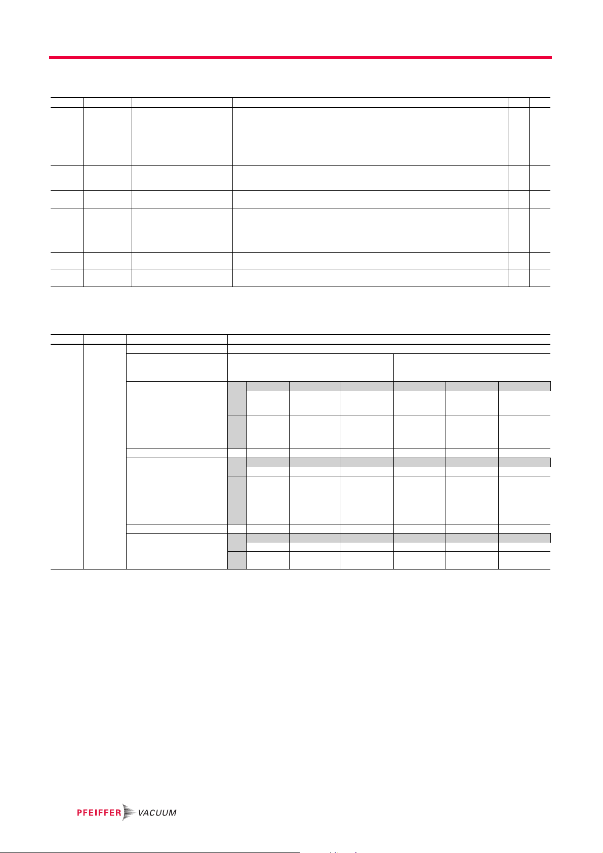
7.2 Maintenance frequency
Description Frequency ACP 15 ACP 15 G
Pump overhaul by Pfeiffer Vacuum service center.
Maintenance frequencies are typical values for non corrosive applications. For applications using G version pump, these values can be reduced. Contact the service center
(see 10).
In general no maintenance is required before product overhaul in your service
center(see 10).
Life-time Under normal operating conditions (at ambient temperature, low humidity and neutral
pumped gas), in a non-polluted environment, a new pump which is regularly maintained
according to the instructions in this manual (subject to the components becoming obsolete) has a life-time greater than 10 years.
7.3 Maintenance on the customer’s site
The pump does not require any maintenance on the customer’s site apart from that described in this manual. All other maintenance must be carried out by your service center
(see 10).
Clean the outer surfaces of the product using a clean, lint-free cloth and a product that
will not damage the screen-printed surfaces and adhesive labels.
20,000 h or 4 years
32
Cleaning of the air ventilation grids with a cloth to remove dust. Do not use com-
pressed air blower.

7.4 Standard repair exchange
To proceed with a standard exchange, key steps must be followed in sequential order:
– Disconnecting the pump from the installation (see 7.4.1)
– Conditioning the pump for shipping (see 7.4.2)
– Declaration of contamination (see 10)
– Handling the new pump (see 3)
– Installing the new pump (see 5)
When returning a product to our service center, please consult the Service procedure
(see 10) and fill in the contamination declaration available on our website.
7.4.1 Disconnecting the pump from the installation
Risk to the health in the event of contact with toxic substances
During pump disconnection, operator could be in contact with process residues on the
exhaust that could cause severe injury or death.
Take the appropriate safety recommendations to prevent injury. Consult the depart-
ment manager for instructions and safety information.
Maintenance
DANGER
Position the mains switch to O position.
Switch off your main circuit breaker.
Disconnect the main plug (see 5.4.2).
Disconnect the nitrogen purge connector.
Disconnect the pump from the inlet piping and fit a blanking plate on the inlet (see 1 1).
Disconnect the pump from the exhaust and fit a blanking plate on the exhaust port
(see 11).
Remove the pump from the installation.
7.4.2 Conditioning the pump for shipping
After use in clean appli-
cations
After use with traces of
corrosive gases
Product transport and
shipping
Install the connecting accessories provided with the pump when it was first delivered.
Contact the service center to order accessories if necessary (see 11).
Join the cover plug (delivered with the pump) connected to the remote connector.
Respect safety instructions before working on the product (see 2.1) and (see 7.1).
Install the connecting accessories allowing to seal the pump (see 11).
Join the cover plug (delivered with the pump) connected to the remote connector.
For product transport and shipping, pack it in the original packing and apply the instruc-
tions from the Service procedure (see 10).
33

Decommissioning
8 Decommissioning
8.1 Shutting down for longer periods
Stop the pump according to pump shut-down procedure (see 6.3.1), (see 6.3.2) or
(see 6.3.3).
Disconnect the pump from the installation (see 7.4.1).
Store the pump (see 3.2).
8.2 Re-starting
To restart the pump after a prolonged storage, refer to the installation instructions (see 5).
8.3 Disposal
According to the regulations 2012/19/EC about Waste of electrical and electronic equipment, and 2011/65/EC about Restriction of Hazardous substances, the manufacturer
provides a paid recycling service for the end of life of the equipment.
Any obligation of the manufacturer to take back such equipment shall apply only to complete not amended or modified equipment, using Pfeiffer Vacuum SAS original spare
parts, delivered byPfeiffer Vacuum, containing e.g. all its components and subassemblies.
This obligation will not cover the shipping cost to a Pfeiffer Vacuum reclamation facility.
Before returning the product, please consult the Service procedure (see 10). Fill in the
declaration of contamination form available on our website. Attach it to the product before shipping to the closest service-repair office.
WARNING
Environmental protection
The product or its components must be disposed of in accordance with the applicable
regulations relating to environmental protection and human health, with a view to reducing natural resource waste and preventing pollution.
The materials Our products contain different materials which must be recycled:
Description SD version G version
Jet - Brass
Purge line - Stainless steel
Val ves FP M
O-rings, lip seals FPM / NBR / PTFE
Shaft, spring, inlet filter Stainless steel
Stators, lobes Aluminum, aluminum alloy
Screws, worked pins, deflectors Stainless steel
Ball barings Steel, PFPE grease
Inlet and exhaust flanges Aluminum
Take particular precautions for:
● fluoroelastomers which may breakdown if they are subjected to high temperatures.
● components in contact with the products resulting from the processes which may have
been contaminated.
+ Al
2O3
coating
34
This list of materials corresponds to the products listed in the chapter (see 1.1). Contact
us for products with specific features.

Malfunctions
9 Malfunctions
Read the safety instructions for maintenance (see 7.1).
9.1 Trouble at pump start-up
Symptom Cause Remedy
The pump does not start and the
fan does not run
The pump does not start but the fan
runs
9.2 The pump runs incorrectly
Symptom Cause Remedy
Pump runs intermittently Temperature Check the pump ventilation conditions (see 5.1).
Pump noisy Gas ballast Check if the gas ballast is open.
Bad vacuum Gas ballast Check if the gas ballast is open.
Mains switch Check the mains switch position to I.
The pump supply voltage is not compatible with
the equipment's power configuration
Main cable not correctly connected or damaged Check / replace the main power cable.
Other problem Contact your service center.
Temperature Check the pump ventilation conditions (see 5.1)
Remote control connector wiring Check that the cover plug is properly connected to
Other problem Contact your service center.
The pump supply voltage is not compatible with
the equipment's power configuration
Other problem Contact your service center.
The pressure does not go down - leak in the installation
Vibration Check that the pump is properly attached to the
Other problem Contact your service center.
Purge (G and CV versions) if the purge is used: check the purge connection
Rotation speed If remote controlled via RS-485: check the value of
Pumping of condensable vapors If the application allows it, let the pump to run for
Defective gauge Check the accuracy of the measurement means.
Leak in the installation Perform a leak test on the pumping line.
Other problem Contact your service center.
Check the equipment’s voltage corresponds to re-
quired power voltage (see 1.2.4).
Wait for 1 hour at ambient temperature between
12 °C et 40 °C. The pump must start automatically
(see 6.1).
the remote connector at the rear of the pump.
Check the equipment’s voltage corresponds to re-
quired power voltage (see 1.2.4).
Warning: if the application requires it, the gas ballast must remain open despite the noise!
Check the pressure at the pump inlet
(see 6.1).
frame.
Warning: if the application requires it, the gas ballast must remain open despite the noise!
between pump and installation.
If the purge is not used: check the tightness of the
plug installed on the purge port.
the speed set point (see 5.6.3).
If remote controlled via dry contacts: check the
contact setting (see 5.5.2).
30 min to 1 hour with gas ballast open; this evacuates the condensable vapors.
35

Service
10 Service
Pfeiffer Vacuum offers first-class customer service!
● On-Site maintenance for many products
● Overhaul/repair at the nearby Service Location
● Fast replacement with refurbished exchange products in mint condition
● Advice on the most cost-efficient and quickest solution
Detailed information, addresses and forms at: www.pfeiffer-vacuum.com (Service).
Overhaul and repair at the Pfeiffer Vacuum Service Center
The following general recommendations will ensure a fast, smooth servicing process:
Fill out the "Service Request/Product Return" form and send it to your local Pfeiffer
Vacuum Service contact.
Include the confirmation on the service request from Pfeiffer Vacuum with your ship-
ment.
Fill out the declaration of contamination and include it in the shipment (mandatory!).
The Declaration of contamination is valid for any product/device including a part exposed to vacuum.
Dismantle all accessories and keep them.
Close all the flange opening ports by using the original protective covers or metallic
airtight blank flanges for contaminated devices.
If possible, send the pump or unit in its original packaging.
Sending contaminated pumps or devices
No devices will be accepted if they are contaminated with micro-biological, explosive, or
radioactive substances. "Hazardous substances" are substances and compounds in accordance with the hazardous goods regulations (current version).
Neutralize the pump by flushing it with nitrogen or dry air.
Close all openings airtight.
Seal the pump or device in suitable protective film.
Return the pump/device only in a suitable and sturdy transport container and send it
in while following applicable transport conditions.
Pump or device returned without declaration of contamination form fully completed and/
or not secured in suitable packaging will be decontaminated and/or returned at the shipper’s expense.
Exchange or repair
The factory operating parameters are always pre-set with exchange or repaired devices.
If you use specific parameters for your application, you have to set these again.
Service orders
All service orders are carried out exclusively according to our general terms and conditions for the repair and maintenance, available on our website.
36

Accessories
11 Accessories
Accessory Description Dimension Model P/N
Inlet filter Installed on the pump inlet, it allows to collect particles
Exhaust silencer It allows to reduce noise level at the exhaust when the
Noise reduction cover In order to reduce significantly noise level.
Sound enclosure kit In order to reduce significantly noise level.
Frequency converter interface
plug
Pump fastening kit It allows to fasten the pump in the equipment with
Wheel kit It allows to install 4 wheels on the frame to move eas-
Automatic gas ballast It ensures tightness when the pump stops or it can be
Isolation valve Installed upstream of the pump, it enables the pump to
Connecting accessories Centering ring with FPM o-ring DN 25 ISO-KF
with a diameter greater than 25 microns (in clean applications such as vacuum packing, metallurgy, lamp
manufacture, evaporation, etc...).
pump operates at high pressures, on clean applications.
Noise level reduction at atmospheric pressure (12 dBA).
Noise level reduction (-5 dBA) at 35 °C. max. ambient
temperature
Noise level reduction (-10 dBA) at 32 °C. max. ambient temperature.
and to manage a power supply up to 24 VDC - 1 A. 112851
plates (M6 screws for frame assembly not supplied)
(compatible with all pump models).
ier the pump (compatible with all pump models).
used to remote control cyclical air inlets (compatible
with all pump models).
be reset to the atmospheric pressure by isolating it
from the pumping line.
Blanking plate in stainless steel DN 25 ISO-KF
Quick-connect clamp DN 25 ISO-KF
Table 1: Refer to the accessory operating instructions to install the accessory.
DN 25 ISO-KF IPF 25 111649
DN 25 ISO-KF ES25S 109873
NRC 15 111968
SEK 15 122480
112846
111138S
230 V 50/60Hz
200 V 50/60 Hz
110 V 60 Hz
100 V 50/60 Hz
24VDC
ISV 25 - 240 V 50/60 Hz
ISV 25 - 220 V 50/60 Hz
ISV 25 - 200 V 50/60 Hz
ISV 25- 110 V 50/60 Hz
ISV 25 -100 V 50/60 Hz
ISV 25 - 24VDC
ISV 40 - 240 V 50/60 Hz
ISV 40 - 220 V 50/60 Hz
ISV 40 - 200 V 50/60 Hz
ISV 40- 110 V 50/60 Hz
ISV 40 - 100V 50/60 Hz
ISV 40 - 24VDC
DN 16 ISO-KF
DN 16 ISO-KF
DN 16 ISO-KF
114812
114815
114813
114814
114816
115899
115898
115897
115901
115900
115902
118815
118814
118813
118812
118811
118816
068189
068193
068196
068195
083264
083333
37

Technical data and dimensions
12 Technical data and dimensions
12.1 General
Basic principles for the Technical Data of Pfeiffer Vacuum Turbopumps:
● Recommendations of PNEUROP committee PN5
● ISO 21360; 2007: "Vacuum technology - Standard methods for measuring vacuum-
pump performance - General description"
● Sound pressure level at ultimate pressure according to EN ISO 2151
12.2 Technical data
Techni cal data Unités ACP 15 ACP 15 G
Inlet flange (ISO-KF) DN 25 DN 25
Exhaust flange (ISO-KF) DN 16 DN 16
Pumping speed max. m
Typical ultimate pressure
(without purge nor gas ballast)
Typical ultimate pressure
(with gas ballast open)
Typical ultimate pressure
(with purge)
Maximum ultimate pressure
(without purge nor gas ballast)
Maximum ultimate pressure
(with gas ballast open)
Maximum ultimate pressure
(with purge)
Max. pumping capacity of pure water vapor
(gas ballast open)
Continuous inlet pressure, Max. hPa 1013 1013
Maximum exhaust pressure hPa 1200 1200
N
Purge flow
2
Gas ballast flow at atmospheric pressure m
Sound level
(gas ballast and purge closed)
Helium leak rate
Power supply
(according to ordering guide)
Power consumption at ultimate pressure W 450 450
Power consumption at atmospheric pressure W 550 550
Dimensions (see 12.4) (see 12.4)
Weight kg 23 23
(1) In accordance with EC regulations, the pumps can withstand a voltage variation of ±10%.
(2) at ambient temperature: 20°C.
(3) Inert gas flushing 300 hPa relative pressure.
(4) Test by Helium spray.
(3)
(3)
(2)
(3)
(4)
(1)
3
/h 14 14
hPa 3·10
hPa 1·10
-2
-1
3·10
-
hPa - 1·10
hPa 5·10
hPa 3·10
-2
-1
5·10
-
hPa - 3·10
g/h 80 80
slm - 5
3
/h 0.5 -
dB(A) < 70 < 70
hPa l/s < 5 · 10
-7
< 5 · 10
V 110-230 V- 1-phase or
200-440 V- 3-phase
-2
-1
-2
-1
-7
38
Conversion table: pressure units
mbar bar Pa hPa kPa Torr
mbar 1 1 · 10
bar 1000 1 1 · 10
Pa 0.01 1 · 10
hPa 1 1 · 10
kPa 10 0.01 1000 10 1 7.5
Tor r
1.33 1.33 · 10
mm Hg
-3
-5
-3
-3
100 1 0.1 0.75
5
1 0.01 1 · 10
1000 100 750
-3
100 1 0.1 0.75
133.32 1.33 0.133 1
1 Pa = 1 N/m
2
mm Hg
7.5 · 10
-3
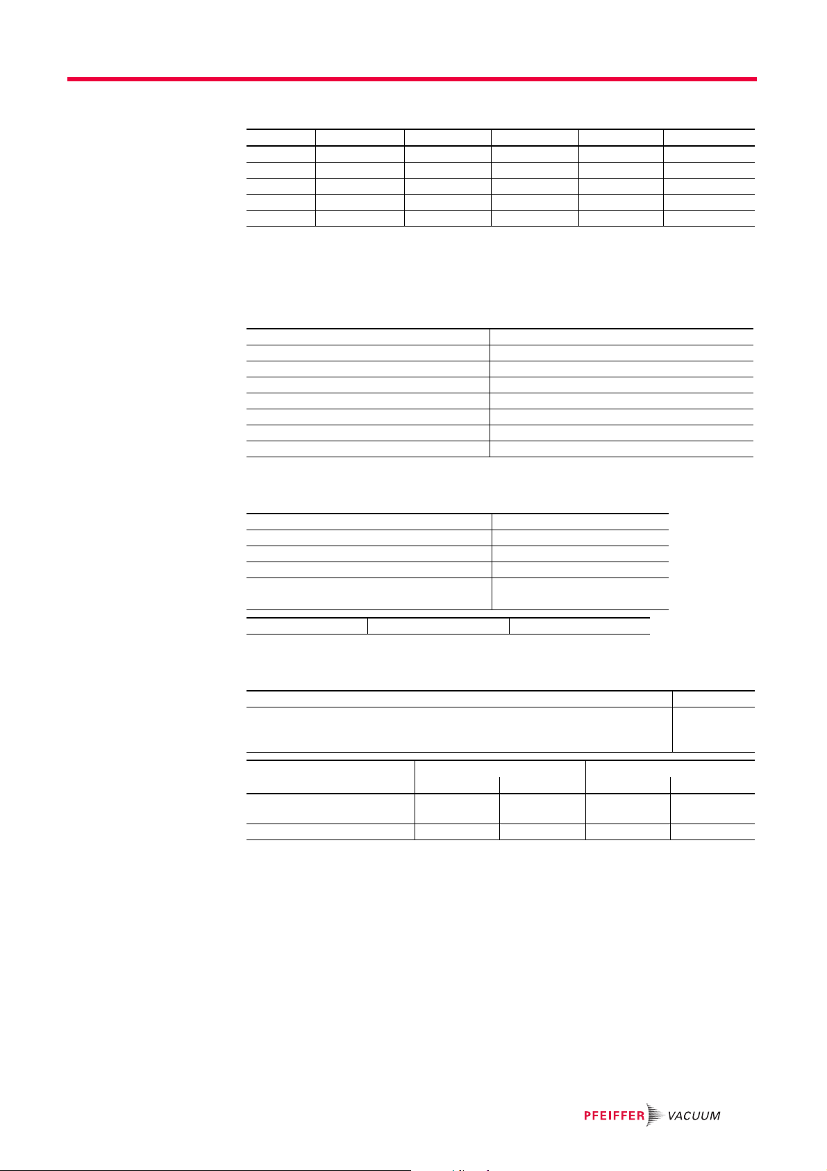
Conversion table: gas throughput units
mbar·l/s 1 0.1 59.2 0.75 0.987
3
Pa·m
/s 10 1 592 7.5 9.87
sccm 1.69 · 10
Torr·l/s 1.33 0.133 78.9 1 1.32
3
atm·cm
/s 1.01 0.101 59.8 0.76 1
12.3 Facilities characteristics
12.3.1 Environmental conditions
Use indoor use
Installation altitude up to 2000 m
Ingress protection IP20
Ambient operating temperature 12-40 °C
Storage temperature -10-+60 °C
Relative humidity max. 80% at T ≤ 31°C, up to max. 50% at T ≤ 40°C
Overvoltage protection category II
Pollution degree rate 2
Technical data and dimensions
mbar·l/s Pa·m3/s sccm Torr·l/s atm·cm3/s
-2
1.69 · 10
-3
1 1.27 · 10
-2
1.67 · 10
-2
12.3.2 Nitrogen characteristics
H2O concentration < 10 ppm v
O
concentration < 5 ppm v
2
Dust < 1 µm
Oil < 0.1 ppm v
Absolute pressure
(before pressure reducer, supplied by customer)
Nitrogen inlet 1/4 BSPT male connector Stainless steel
12.3.3 Electrical characteristics
Circuit breaker with a minimum interrupting short circuit current 10 kA
GFI (or RCD) type B, differential circuit breaker compatible with type T.T electrical net-
work
1) For other networks, types T.N or I.T, use the proper protection device
Power supply LV (100-115V) HV (200-230V) LV (200-240V) HV (240-440V)
Main circuit breaker rating (minimum values)
Cable wire specifications 2.5 mm
5
1.5 ·10
Pa
30 mA
Single-Phase Three-Phase
12 A 6 A 5 A 3A
2
1.5 mm
2
1.5 mm
2
1 mm
1)
2
39

Technical data and dimensions
J
I
H
E
AA
L
C
B
N
K
AC
Q
T
F
D
T
M
A
AB
R
G
U
S
1
2
3
100
150
215
BABA
72 270
12.4 Dimensions
Fig. 7: ACP 15 /ACP 15 G - Dimensions (mm)
1 Purge port (ACP 15 G model)
2 Hoisting ring (with single-phase frequency converter)
3 Hoisting rings (with three phase frequency converter)
ACP 15/ACP 15 G A B C D E F G H I J K L M N Q R S T U AA AB AC
Single-phase 272 498 475 11 207 - - 239 284 409 150 300 85 93 7 - - 15 - 44 - 190
Three-phase 272 497 477 18 207 266 170 238 283 408 150 300 84 95 7 52 208 15 235 44 30 190
Wheel kit dimensions
40
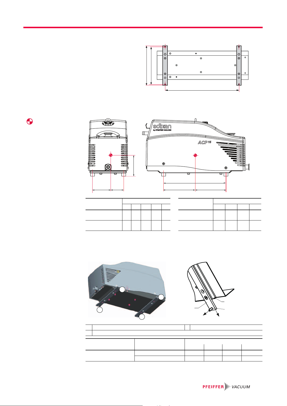
Fastening kit dimensions
254
240
BABA
Fr
Fa
8
7
6
BA = 300 mm
12.5 Weight distribution and seismic brackets
Center of gravity
Technical data and dimensions
Load on foot with
fastening kit
Z
300
X2
X1
Y1
Y2
Model Center of gravity (mm) Model Load by foot (daN)
X1 X2 Y1 Y2 Z F1 F2 F3 F4
ACP 15/ACP 15 G
Single-phase
ACP 15/ACP 15 G
Three-phase
65 85 156 144 110 ACP 15/ACP 15 G
Single-phase
67 83 157 143 116 ACP 15/ACP 15 G
Three-phase
6.8 5.2 6.3 4.8
6.7 5.4 6.1 4.9
It is strongly recommended to secure the pump on the host tool with 4 screws (supply of
these screws is the customer’s responsibility, at least 2 screws per fixation plate). The
screw material must comply with foot load specifications, given in the table below.
F1
F3
F2
F4
6 Pump frame 8 M 6 X 20 screw ,qty 4, grade 12-9
7 Fastening plate, thickness: 6 mm (delivered in the fastening kit)
Model Load per foot (N)
F1 F2 F3 F4
ACP 15 /ACP 15 G
Single-phase/Three-phase
Tension (Fa) 120 -13 72 31
Shearing (Fr) 85 25 87 52
41
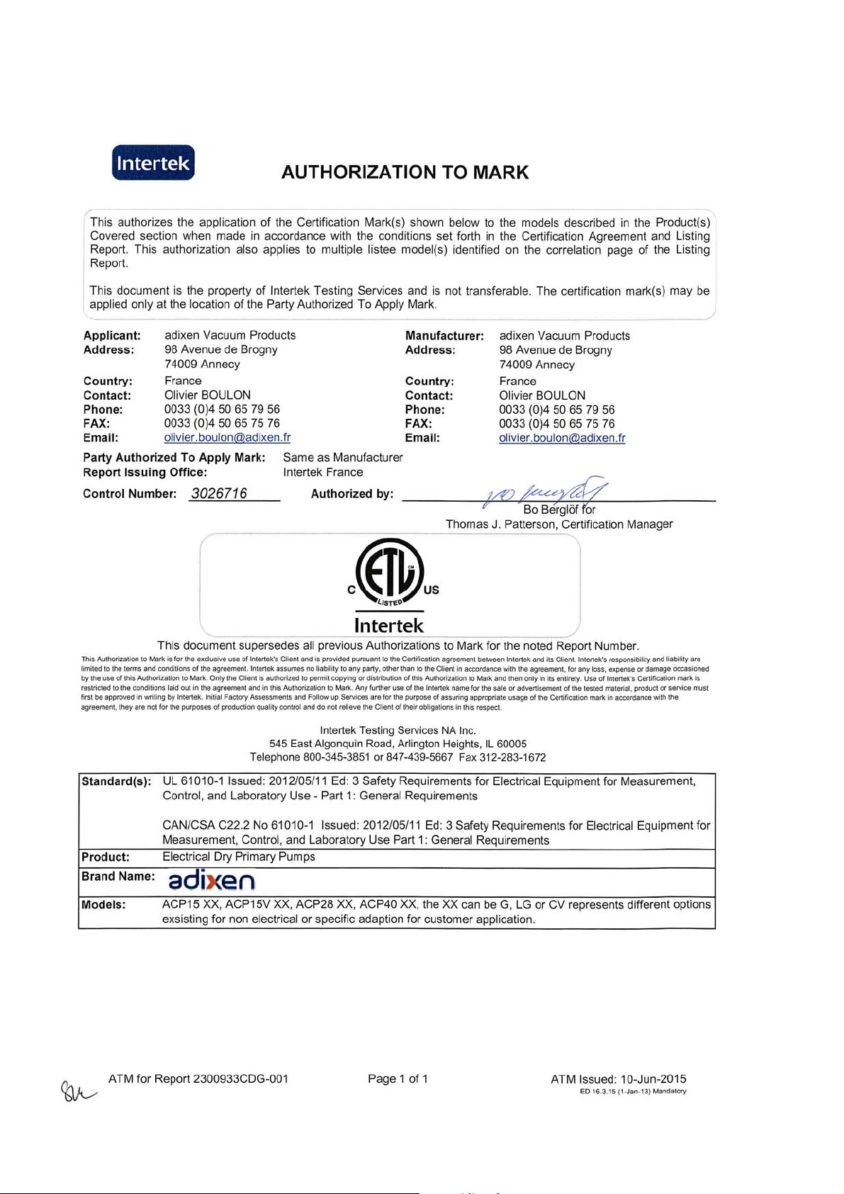
ETL Mark

Declaration of conformity
We hereby declare that the product cited below satisfies all relevant provisions accord-
ing to the following EC directives:
● Machinery 2006/42/EC (Annex II, no. 1 A)
● Electromagnetic Compatibility 2014/30/EU
● Restriction of the use of certain Hazardous Substances 2011/65/EU
● Low Voltage 2014/35/EU
The technical file is drawn up by Mr Gilles Baret, Pfeiffer Vacuum SAS, [simplified joint
stock company], 98, avenue de Brogny · B.P. 2069, 74009 Annecy cedex.
ACP 15 - ACP 15 G
Harmonised standards and national standards and specifications which have been applied:
Signatures:
(M.Taberlet)
President
Standard NF EN-1012-2 : 2009
Standard NF EN-61010-1 : 2011
Standard NF EN-61000-6-2 : 2005
Standard NF EN-61000-6-4 : 2007
(M. Baret)
Products and Technologies Director
Pfeiffer Vacuum SAS
98, avenue de Brogny
B.P. 2069
74009 Annecy cedex
France
01/07/15

VACUUM SOLUTIONS FROM A SINGLE SOURCE
Pfeiffer Vacuum stands for innovative and custom vacuum solutions worldwide,
technological perfection, competent advice and reliable service.
COMPLETE RANGE OF PRODUCTS
From a single component to complex systems:
We are the only supplier of vacuum technology that provides a complete product portfolio.
COMPETENCE IN THEORY AND PRACTICE
Benefit from our know-how and our portfolio of training opportunities!
We support you with your plant layout and provide first-class on-site service worldwide.
Ed 01- Date 2015/09 -P/N:123884OEN
*123884*
Are you looking for a
perfect vacuum solution?
Please contact us:
www.pfeiffer-vacuum.com
Pfeiffer Vacuum GmbH
Headquarters • Germany
T +49 6441 802-0
info@pfeiffer-vacuum.de
 Loading...