


Temperature probes
type T/TW
Contents
Content
1 General
1 Preface
1.1 Introduction
2 General instructions
1.2 Scope
2.1 Operating range
1.3 Continuous glass monitoring
2.2 Warnings contained in the operating
2 Safety instructions
instructions (OI)
2.1 General safety notes
2.3 Notes on deliveries
2.2 Product-specific safety notes
2.4 Transport and storage
2.3 Safety instructions for accessing reactors
2.5 Warranty notes
2.4 Avoiding damages to the glass
2.6 Notes on return deliveries
3 Storage
3 Safety
4 Transport
3.1 Proper use
5 Product description
3.2 Qualified personnel
4 Glass-lined temperature probes
4.1 Probe types
4.2 Joint features and properties
4.3 General information
4.4 Avoiding damages to peripheral devices
Contents
5 Temperature probe type T
5.1 Measuring principle
5.2 Construction of the T probe
1 General
5.3 Transmitter TTH300 Ex
1.1 Introduction
5.4 Technical data of T probe
1.2 Scope
5.5 Installation of the T probe
1.3 Continuous glass monitoring
5.6 Connection of the T probe
5.7 Start-up and maintenance of the T probe
2 Safety instructions
5.8 Calibration of the T probe
2.1 General safety notes
5.9 Explosion protection
2.2 Product-specific safety notes
6 Temperature probe type TW
2.3 Safety instructions for accessing
6.1 Measuring principle
reactors
6.2 Construction of the TW probe
6.3 Transmitter TTH300 Ex
2.4 Avoiding damages to the glass
6.4 Technical data of TW probe
3 Storage
6.5 Installation of the TW probe
4 Transport
6.6 Connection of the TW probe
5 Product description
6.7 Start-up and maintenance of the TW probe
6.8 Calibrating the TW probe
6.9 Explosion protection
Operating Instructions
302-10 e
Annex 1
PTB 03 ATEX 2132 X
Annex 2
Declaration of conformity
Annex 3
A 3.1 Potentially hazardous
atmospheres
A 3.2 Atmospheric conditions
A 3.3 Equipotential bonding
A 3.4 Lightning protection
A 3.5 Quatro-Pipe

Temperature probes type T/TW
Temperature probes type T/TW
1 Preface
The present operating instructions are
designed to familiarize users with the
construction of the glass-lined temperature probes and their use.
The operating instructions should be
accessible to the operating and maintenance personnel in order to ensure that
all necessary information is available for
any assembly and maintenance work.
By knowing these operating instructions
(OI), you can avoid damage to the measuring equipment and ensure trouble-free
operation. The information contained
in these operating instructions corresponds to the state of the art at the time
it is printed and is provided to the best
of our knowledge. We reserve the right to
include any improvements, amendments
and new developments in the operating
instructions without prior notice. The
actual design of products may differ from
the information provided in the catalog
if warranted by technical modifications
resulting from product improvements.
The proposal submitted by Pfaudler for
a concrete application will be binding in
this case. The latest edition will always
supersede all previous ones.
The present operating instructions are
made available to our customers and
interested parties free of charge. Reprints
and copies as well as transformation into
electronic forms, in whole or in part, shall
require our written approval.
2.2 Warnings contained in the operating instructions (OI)
In the operating instructions, the
danger symbol m is used to draw
your attention to especially important safety instructions. Compliance
with these instructions is mandatory, because adherence to the
instructions can avoid severe damage to people and/or equipment.
2.3 Notes on deliveries
The respective scope of delivery is specified on the shipping documents attached
to the shipment and corresponds to the
valid purchase agreement.
Check that the items delivered are complete and intact.
If possible, keep the packing material for
re-use for possible return shipments.
2.4 Transport and storage
The probes should only be transported
and stored in their closed original packaging. Where it is no longer available, the
probes must be protected against shock
and impacts. In order to guarantee an
as-new condition of the probes, maintain
the following storage conditions:
n dry and dust-free
n steady temperature and ventilation
The probes do not need any preservatives, they are resistant to normal environmental influences.
2.6 Notes on return deliveries
Before sending used probes to Pfaudler
Werke GmbH or third parties for repair
or other purposes, all parts must be
cleaned and decontaminated.
To protect our staff and for insurance
reasons, your return shipment must be
accompanied by a clearance certificate
(refer to publication 332) on which you
confirm that the probe was properly
cleaned and decontaminated. You may
obtain a form sheet for this purpose
from us on request.
3 Safety
For detailed safety instructions and information concerning explosion protection,
please refer to the end of the operating
instructions.
3.1 Proper use
Any use of the probe for purposes other
than described in the present operating instructions will adversely affect the
safety and functioning of the measuring
device and is therefore not allowed.
It is important to note the safety instructions applicable to the electrical systems
and equipment and all explosion protection provisions, if any.
m Do not practice any working
me th od s wh ic h ma y en d a n ge r sa fe ty.
All rights reserved.
2 General instructions
2.1 Operating range
Glass-lined temperature probes are used
to measure the product temperature in
reactors and storage vessels as well as
in pipelines.
For the resistance of the probes, please
refer to our publication no. 614.
Never operate this measuring device
outside its permissible operating conditions.
2
2.5 Warranty notes
Any warranty claims shall not be extended
or limited by the information contained in
the present operating instructions.
For the exact warranty conditions, please
refer to the Terms of Sale of Pfaudler
Werke GmbH as amended.
3.2 Qualified personnel
The probe may only be installed, started
up and serviced by authorized personnel
with special skills in measuring technolog y and in strict compliance with the present Operating Instructions as well as the
valid provisions.
The failure to observe these instructions
– no matter whether intentionally or negligently – releases Pfaudler Werke GmbH
from all liability and warranty claims.
© Pfaudler GmbH · OI 302-8 e
© Pfaudler GmbH 2

4 Glass-lined temperature
probes
t [%]
Temperature probes type T/TW
Temperature probes type T/TW
4.1 Probe types
Pfaudler offers two different types of
100
probes for temperature measurement
which operate according to different
physical measuring principles.
These probe types are:
n Temperature probe type T
E T/TW Ta
With this probe, a thermocouple performs the sensing function. Thermocouples are based on the physical
50
effect of a charge shift in an electrical
conductor (wire) along a temperature
gradient. The free electrons move
from the hot end of the wire to the
cold end of the wire.
n Temperature probe type TW
This probe is equipped with a resistance thermometer as the sensor.
Resistance thermometers are based
on the physical effect that the electrical resistance of conductors and
semiconductors changes subject to
the temperature.
4.2 Joint features and properties
Both probe types have a sensor that is
fused into the glass. Thus, the sensor
is excellently protected against aggressive media, and its placed directly in the
product. This arrangement offers users
the following advantages:
n The probes have very short response
times. The response behavior of the
measuring probes type T and TW
is shown in Fig. 1 in comparison to
0 10 20 30 40 50 [s]
Measured in inside the reactor (100 l) with water at 120 rpm
T/TW measuring probe type T/TW on
thermometer well, D = 40 mm
Ta thermocouple with tantalum sensor in
thermometer well, D = 40 mm
E Reference measurement with unprotected
pallaplat element (cannot be used in glass-lined reactor)
Fig. 1 Time response
MT_05_00001
probes with plugged-in sensors.
n The sensors of the probes have not
been simply screwed-in, producing
error-prone sealing surfaces in the
product.
n Due to the quick and precise tem-
perature measurement, the production process can be controlled safely
and economically. In many cases, the
product quality is also improved.
n The sensors are not subject to ageing
because they are made of extremely
pure and highly resistant noble metals and have been fused into the glass
layer in a chemically inert process.
Glass is absolutely diffusion-tight,
therefore, reaction with hydrogen is
also excluded.
© Pfaudler GmbH ·
OI 302-8 e
© Pfaudler GmbH 3
3

Temperature probes type T/TW
Temperature probes type T/TW
4.3 General information
During a spark test, inflammable sparks
may occur at the pores in the form of an
electric arc. Therefore, spark testing may
only be carried out outside of potentially
explosive atmospheres.
4.4 Avoiding damages to peripheral devices
When performing a spark test, please
note the following information; otherwise, the components and/or the electronic transmitter may get damaged.
n The measuring transducers for tem-
perature, glass monitoring, capacitive
sensors and other electronic/electric
components that have been attached
to the valve or the baffle must be disconnected prior to the spark test.
n Suitable equipment must be employed
for the test (impulse voltage). We recommend using the GlaSparker®, our
high-voltage tester
n For glass lined measuring probes, the
max. test voltage must not exceed
7 k V .
n The contact window around the meas-
uring probe site (e. g. P) must not be
tested.
In general, however, we recommend calling our technical service for performing
the test.
5 Temperature probe type T
5.1 Measuring principle
The temperature probe Ty p e T will also
be referred to as the T probe in the
present Operating Instructions.
As already mentioned, a thermocouple
serves as the sensor of the T probe. A
thermocouple consists of two electrical
conductors made of different materials
(wires) that are connected (in contact) to
each other at one end. The contact point
is the measuring location of the thermocouple. The two free wire ends constitute
the reference location of the thermocouple. If the thermocouple is heated in the
measuring location, a thermal voltage is
present in the reference location. This
thermal voltage depends on the temperature difference between the mea suring
location and the reference location (temperature gradient along the thermocouple), and on the material combination
of the two metal wires. For temperature
measurements, the temperature of the
reference location must be kept constant at 0 °C, or it must be precisely measured in order to perform an appropriate
adjustment in mV. To evaluate the thermal voltage, the free wire ends of the
thermocouple (the reference location)
are connected to a suitable transmitter.
m The T probe is not identical to
thermocouple type T.
The standardized thermocouple types
are not suitable for the T probe for reasons of glassing technology. The positive
branch of the T probe is made of a platinum-rhodium alloy (PtRh), the negative
branch is made of a gold-palladium-platinum alloy (AuPdPt). This material combination is known as “pallaplat”. Table 1
shows the values of the basic characteristic of pallaplat. However, these values
may only serve as reference values. The
exact characteristic depends on the
manufacturing batch of the pallaplat.
For programming the transmitter (refer
to Section 5.3), the characteristic that
was determined for the specific pallaplat
batch after production will be used. The
values entered during programming will
be indicated in the test report that is
attached to each probe supplied.
Only the Pfaudler-approved pallaplat
compensating line (part no. 029034)
may be used as an extension for the
thermocouple.
Standard EN 60584 defines the various
material combinations for the production of thermocouples. These standardized material combinations are referred
to as “thermocouple types” and marked
by different capital letters. One of them
is the letter “T“.
4
© Pfaudler GmbH · OI 302-8 e
© Pfaudler GmbH 4

Temperature probes type T/TW
Temperature probes type T/TW
5.2 Construction of the T probe
5.2.1 Probe carrier
The T probe can be installed in various
probe carriers:
n Baffles, thermometer well, Quatro-
Pipe and C baffle (the term tubular
probe will be used below for this type
of probe carriers)
n Ring
probe
n Valve shaft of outlet valves
5.2.2 Tubular probe
The thermocouple of tubular probes consists of very thin, narrow bands made of
the pallaplat material combination. The
pallaplat bands are fused into the glass
layer.
The measuring location, where the two
pallaplat bands are in contact is normally
at the end of the tube in order to measure the product temperature even at
low liquid levels inside the reactor. When
using tubular probes, several measuring
locations may be fitted at the same or at
different levels. The maximum possible
number of measuring locations depends
on the size of the tubular probe. For
more details, please contact the Pfaudler
Instrumentation department.
In order to provide electrical connection
to the thermocouple, the pallaplat bands
fused into the glass are routed close to
the terminal box and connected to the
compensating line. In turn, the compensating line is introduced into the terminal
box where it is connected to the transmitter.
Tubular probes equipped with T probes
can optionally be combined with the
following measuring probes made by
Pfaudler:
n Typ P Measuring probe for glass
monitoring
n Typ FT Measuring probe for capaci-
tive detection of filling limits
or interfaces between liquids
n Typ FS Measuring probe continuous,
capacitive detection of filling
levels
n Typ TW Measuring probe for tem-
perature measurement using a resistance thermometer
For more details about possible combinations, please contact the Pfaudler
Instrumentation department.
5.2.3 Ring probe
The thermocouple of ring probes consists of very thin, narrow bands made of
the pallaplat material combination. The
pallaplat bands are fused into the glass
layer.
The measuring location is in the middle
of the cylindrical inside area. Ring probes
can be produced with a maximum of 4
measuring locations.
In order to provide electrical connection to the thermocouples, the pallaplat
bands fused into the glass are routed
close to the terminal box and connected
to the compensating line. In turn, the
compensating line is introduced into the
terminal box where it is connected to the
transmitter.
Ring probes equipped with T probes can
optionally be combined with the following
measuring probes made by Pfaudler:
n Typ P Measuring probe for glass
monitoring
n Typ FT Measuring probe for capaci-
tive detection of filling limits
or interfaces between liquids
For more details about possible combinations, please contact the Pfaudler
Instrumentation department.
5.2.4 Valve shaft
The measuring location of a probe
mounted on a valve shaft is in the middle of the valve shaft on the product side.
Power supply to the thermocouple is by
means of pallaplat wires that are insulated and routed through the inside bore
of the valve shaft. The wire ends are connected to the compensating line which in
turn is introduced into the terminal box
where it is connected to the transmitter
type TTH300 (or terminals).
With nominal sizes DN 80/50 or more,
the T probe can be installed in a valve
shaf t. A maximum of 2 T measuring locations are possible. Optionally, a T probe
can be combined with the a measuring
probe Type P (for glass monitoring). For
more details about this possible combination, please contact the Pfaudler
Instrumentation department.
© Pfaudler GmbH · OI 302-8 e
© Pfaudler GmbH 5
5

Temperature probes type T/TW
Temperature probes type T/TW
5.3 Transmitter
A transmitter of the type TTH300 made
by ABB is used as a standard for evaluating the signal measured by the T probe
(the thermal voltage). The transmitter is
a freely programmable unit that converts
the measured signals of thermocouples
and of resistance thermo meters into a
standard potential-free 4-20 mA signal.
The transmitter is integrated into the terminal box on the probe carrier already in
the factory where it is also connected to
the sensor lines.
Based on product-dependent tolerances
in the manufacture of pallaplat, the values of the characteristic may slightly
deviate between batches. Therefore, the
batch-specific characteristic is measured
after the production of each batch. During the internal acceptance test in the
factory, the TTH300 is parameterized
with this batch-specific characteristic.
The characteristic has a total of 32 intermediate points. The values of the characteristic are indicated in the test report
that is attached to each probe supplied.
The transmitter is programmed using the
“Smart Vision” firmware. The TTH300
is also equipped with a HART interface
which allows for programming of the
transmitter on location.
As a rule, it is possible to use other types
or makes instead of the TTH300. However, the following conditions must be
observed in this case:
n The transmitter must be freely pro-
grammable and must be programmed
with the batch-specific pallaplat characteristic. Third-party transmitters
cannot be programmed by Pfaudler
because we do not have the hardware
and software necessary for that purpose. However, Pfaudler will support
you with the programming of thirdparty transmitters.
n The transmitter must have a reference
location.
n Pfaudler cannot provide any binding
information concerning the accuracy
of the measuring system as a whole if
third-party transmitters are used.
If the ambient temperature in the surroundings of the transmitter is excessively high on location (refer to Sect. 5.4),
the transmitter must be installed next to
the probe carrier in an area in which the
temperature is lower. A pallaplat compensation line must be used to connect
the terminal box on the probe carrier
to the transmitter. Suitable compensating lines are available from Pfaudler
(part no. 029034).
For more details concerning the transmitter, please refer to the documentation
that is attached to each probe supplied.
6
m The T probe must in all cases
be operated in conjunction with a
freely programmable transmitter,
otherwise, the temperature measurement will not be correct.
© Pfaudler GmbH · OI 302-8 e
© Pfaudler GmbH 6

5.4 Technical data of T probe
Sensor material: Pallaplat
pos. branch made of platinum-rhodium
neg. branch made of gold-palladium-platinum
Resistance of pallaplat: 30 Ω /m
Resistance of the compensating line: 0,33 Ω /m
min/max temperature in
the terminal box: – 40/+80 °C
min/max operating temperature: – 25/+200 °C
Measuring variance: max. ± 1,5 °C
Temperature probes type T/TW
Temperature probes type T/TW
Electrical data if used in potentially explosive atmospheres:
Please note the details in the type examination certificate
PTB 03 ATEX 2132 X in annex 1.
© Pfaudler GmbH ·
OI 302-8 e
© Pfaudler GmbH 7
7
Temperature probes type T/TW
Temperature probes type T/TW
5.5 Installation of the probe carriers
5.5.1 Installation of tubular probe
The term tubular probe is used for the
following probe carriers in this context:
n Baffles
n Thermometer well
n Quatro-Pipe
n C baffles
Before installing a tubular probe in a
reactor or a pipeline, you should verify
whether there is sufficient distance to
the agitator and the reactor wall. If necessary, suitable spacers or reducing
flanges must be used.
Assembly process:
t Place flange gasket on nozzle.
t Protect the nozzle and the probe
against damage by inserting a piece
of cloth or a PTFE sleeve into the nozzle. Slowly introduce the tubular probe
into the reactor through the nozzle.
Avoid pendulum motion.
t Tighten flange screws evenly cross-
wise with the prescribed tightening
torque; (cf. Tab. 3).
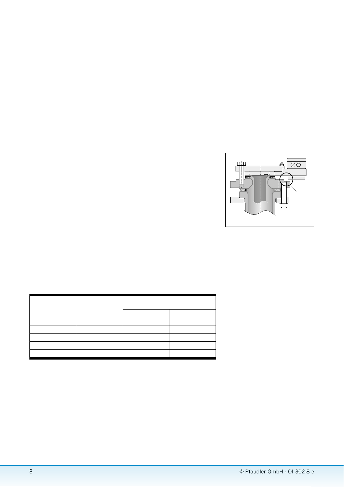
m When using your own reduc-
ing flanges, please make sure that
the element covering the contact
area below the terminal box does
not sit on the reducing flange (cf.
Fig. 2). In the event of non-compliance, the glass may be damaged at
the bottom side of the flange, and
the fused-in metal strips may be
interrupted.
5.5.2 Installation of ring probe
The ring probe may generally be installed
in any position inside the pipeline. However, it must be noted that the T probe
does not work unless the measuring location is sufficiently covered with product. In
radial direction, the measuring location is
in the same place as the terminal box.
The ring probe is be installed in the pipeline between 2 flanges using gaskets.
Tighten flange screws evenly crosswise
with the prescribed tightening torque;
(cf. Tab. 3).
5.5.3 Installation of outlet valve
For details concerning the installation,
please refer to our Operating Instructions 322.
These Operating Instructions are attached
to each valve supplied. They are available
from Pfaudler on request.
collision
area
MT0010_1E
Fig. 2 Installation example with reducing flange
Table 3 Tightening torques of glass-lined flange connections
Flange Screws Max. tightening torques in Nm with admis-
DN50 4 x M16 30 30
DN80 8 x M16 35 35
DN100 8 x M16 35 35
DN150 8 x M20 40 40
DN200 8 x M20 55
sible operating pressures of:
–1 to +10 bar –1 to +16 bar
8
© Pfaudler GmbH · OI 302-8 e
© Pfaudler GmbH 8
Temperature probes type T/TW
Temperature probes type T/TW
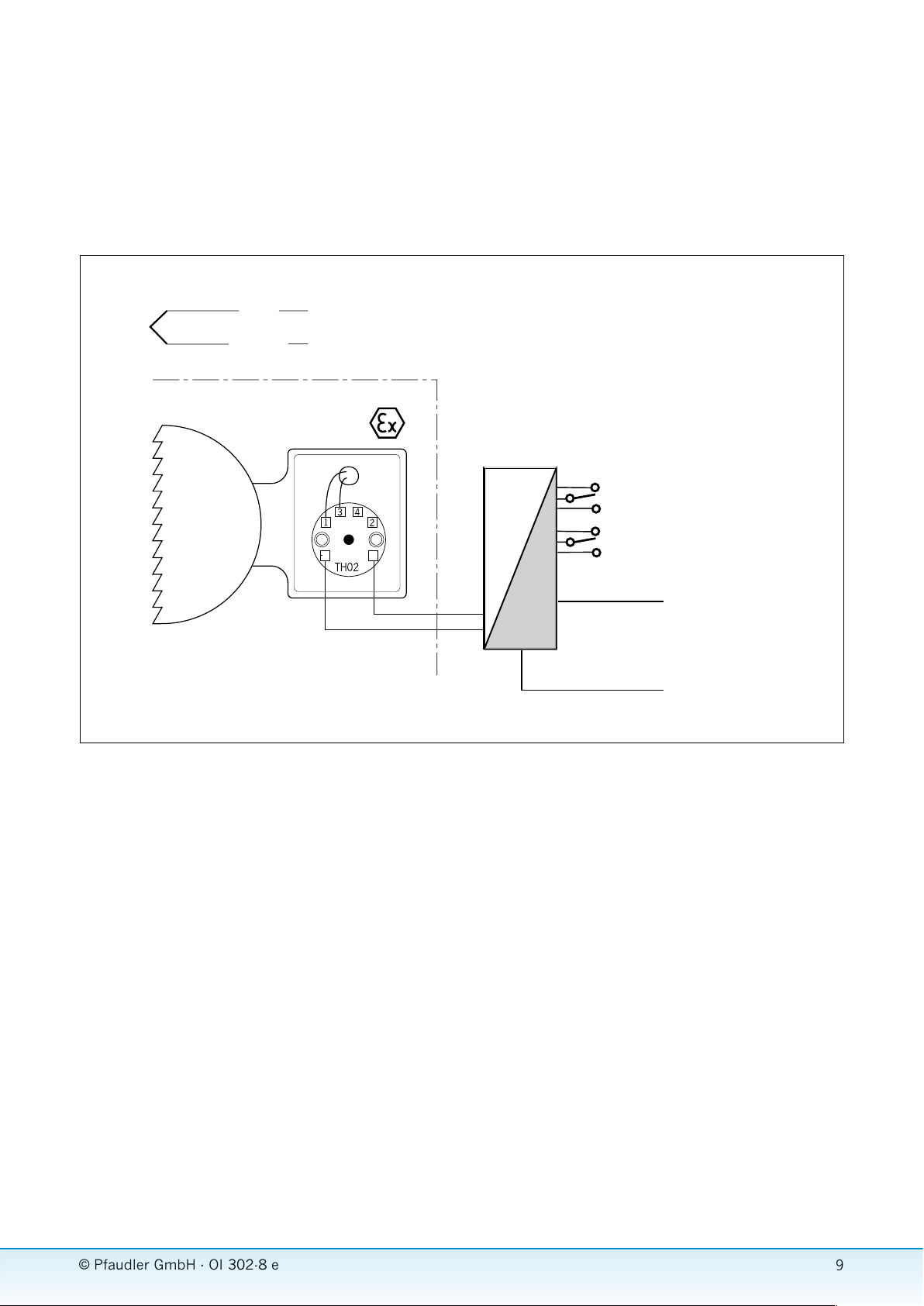
+ red
– violett
T probe
Fi
g. 3 Connection diagram of the T probe
3
1
power supply unit with electrical
isolation Ex ia/ib
max. 30 V DC 100 mA
optional floating
change-over
contacts
}
+5
6
current output
4 -2 0 m A
power Supply 24 V DC/AC
(230 V AC)
MT_05_003_1e
5.6 Connection of the T probe
The following information only applies to
T probes in c
onnection with the TH02-Ex
transmitter.
A power supply unit with the following
specifications is necessary for power
supply:
n Supply current: I
n Supply voltage: U
n in potentially explosive
= 0 - 20 mA
S
= 8,5 ... 30 V DC
S
atmospheres: Ui = 8,5 ... 29,4 V DC
For applications in potentially explosive
atmospheres, power supply units in
intrinsically safe design must be used.
The power supply unit must be installed
outside the potentially explosive area.
The installation instructions of the manufacturer are mandatory in this respect.
The connection between the power supply unit and the transmitter can be made
using standard signal cables.
The probe carriers must be grounded
using copper or stainless steel wires with
a minimum conductor area of 10 mm2.
The electrical connection is made in
compliance with the connection diagram
shown in Fig. 3. Connection is identical
for all probe carriers.
5.7 Start-up and maintenance of the T probe
No start-up procedure is necessary for T
probes supplied together with the standard transmitter. When the transmitter
has been connected to the power supply
unit, the T probe is ready for use. However, we recommend verifying whether
the transmitter’s measuring range as set
by Pfaudler complies with your requirements. The measuring range setting is
indicated on a rating plate each on the
transmitter and in the terminal box as
well as in the test report.
If necessary, the measuring range can
be changed. Upon final acceptance in
the factory, a functional test and a single-point calibration will be performed.
A test report will be prepared which is
attached to each probe.
If the T probe is ordered and delivered
without a transmitter, it is the operator’s
responsibility to ensure that a suitable
transmitter is used and configured (refer
to Sect. 5.3). The values comprised in
the characteristic of the thermocouple
are provided in the attached test report.
Due to its special construction (thermocouple fused into glass layer) and noncritical operating conditions, the probes
are not subject to ageing. Therefore,
inspections (calibration) of the thermocouple are not necessary for measuring
reasons. As a result, the T probe is maintenance-free.
© Pfaudler GmbH · OI 302-8 e
© Pfaudler GmbH 9
9

Temperature probes type T/TW
Temperature probes type T/TW
If it is used for processes, however, which
are associated with the risk of product
deposits, it must be verified whether
or not product has accumulated on the
probe carrier. Deposits must be removed
using suitable means and methods.
5.8 Calibration of the T probe
5.8.1 General instructions
As mentioned before, the thermocouple
has been fused into the glass layer, thus
forming an integral part of the probe carrier. Calibrating the thermocouple separately is not possible for this reason. It is
most practical to calibrate the T probe
with the probe carrier installed because
stable, reproducible temperature conditions at the T probe are most conveniently achieved. Calibration outside the
reactor or pipeline is very problematic
because there is considerable heat dissipation, which results in instable temperature conditions at the thermocouple,
due to the shape and size of the probe
carriers. For calibration, the reactor or
the pipeline must be filled either with
product or with water. A steady temperature at the transmitter must be ensured
during calibration. For this reason, the
terminal box should be closed.
For calibrating tubular probes, the reactor must be filled until the immersion
depth of the measuring location is at
least five times the tube diameter. When
calibrating inside a reactor, the agitator
must turn slowly in order to ensure an
even temperature distribution inside the
liquid.
For ring probes, the pipeline must be
fully filled. Ring probes may also be calibrated outside the pipeline due to their
compact dimensions. For this purpose,
the probe must then be immersed into a
suitable vessel. Caution! Do not immerse
the terminal box.
When calibrating outlet valves, the valve
cone must be sufficiently covered with
product so as to ensure a stable temperature condition in the measuring
location. Furthermore, the agitator must
be slowly turned during calibration.
5.8.2 Calibrating the measuring
chain
In order to calibrate the entire measuring
chain including the sensor, transmitter
and display unit, immerse a calibrated
reference thermometer into the liquid
and compare its measured value (reference value) with the value measured by
the T probe (actual value). If it is necessary to calibrate the T probe at different
temperatures, we recommend calibrating it in icy water at 0 °C and in boiling
water at 100 °C.
The result will be reliable information
concerning the accuracy of the entire
measuring chain and the actual temperature conditions in the subsequent production process.
If an excessive, inadmissible measuring
deviation is detected during calibration,
the individual elements of the measuring
chain must be verified or calibrated.
5.8.3 Calibrating the sensor
Actually, it is not necessary to calibrate
the sensor (thermocouple) for technical
reasons because the sensor is not subject to ageing (refer to Sect. 5.7).
However, in some cases the sensor has
to be calibrated to comply with internal
or process-related requirements. The
Pfaudler T-Calibrator (part no. 256572-)
and the Smart Vision firmware must be
available in order to calibrate the thermocouple. For more information and a
detailed description of the calibration
process, please refer to the Operating
Instructions of the T-Calibrator.
5.8.4 Calibrating the transmitter
In order to calibrate the transmitter, a
process calibrator is connected to the
transmitter input that serves to simulate
the thermocouple‘s characteristic. Then,
the voltage values of the characteristic
are entered one by one at the process
calibrator. In parallel, the actual values
of the transmitter (input and output signal) are compared to the programmed
values (values of the characteristic). The
values of the characteristic are indicated
in the test report that is attached to each
probe supplied. It is important to deactivate the internal reference point of the
transmitter during calibration. Please
refer to the Operating Instructions of the
TH02-Ex unit for a description of how to
deactivate the reference point.
5.8.5 Calibrating the display unit
In order to calibrate the display unit,
an additional, calibrated display unit
is looped into the transmitter’s output
circuit, and the two values displayed as
actual and programmed values must be
compared.
5.9 Explosion protection
The tubular and ring probes with an
integrated T probe have been approved
for use in potentially hazardous atmospheres of zone 0 in accordance with the
EC type examination certificate No. PTB
03 ATEX 2132 X. For outlet valves with
an integrated T probe, an EC type examination certificate has been applied for.
10
© Pfaudler GmbH · OI 302-8 e
© Pfaudler GmbH 10

Temperature probes type T/TW
Temperature probes type T/TW
6 Temperature probe type TW The resistance values of resistance ther-
mometers made of platinum have been
6.1 Measuring principle
The temperature probe Type TW w
also be referred as the TW probe in the
present Operating Instructions.
standardized and are referred to as Pt 100,
Pt 500 and PT 1000. The number speci-
ill
fies the nominal resistance in Ohm at a
temperature of 0 °C. Therefore, a Pt 100
has a nominal resistance of R0 = 100 Ω .
As already mentioned, a resistance thermometer serves as the sensor of the TW
probe. The measuring principle of resistance thermometers is based on the fact
that the electrical resistance of all conductors and semiconductors changes
For these standardized measuring resist-
ances, basic value series (characteris-
tics) have been specified in EN 60 751.
The measured signal is evaluated by the
transmitter based on this characteristic
in order to determine the temperature.
with the temperature. The amount of
change in referred to as varies depending
on the material used. The relative change
of the electrical resistance as a function
of the temperature, ∆R/∆t, is referred to
as the temperature coefficient. This value
is not constant over the whole temperature range. Rather, it is a function of the
temperature. The relationship between
resistance and temperature is subject
to higher-order mathematical polynomials for calculating the characteristic of a
For the TW probe, no Pt 100 to the EN
standard was used as resistance ther-
mometer. For technical reasons, the
TW probe cannot be produced with an
exact resistance value of 100 Ω . The re-
sistance of the TW probe is 100 ± 3 Ω .
Therefore, it is absolutely necessary to
use a programmable transmitter (refer
to Sect. 6.3) that compensates the de-
viation from the 100 Ω characteristic in
order to evaluate the measured signal.
resistance thermometer.
The special properties of platinum, such
as high measuring accuracy, high temperature resistance, chemical resistance,
an approximately linear characteristic as
well as an excellent reproducibility of the
thermo-electrical properties, were reason
enough to produce most resistance thermometers from this metal today. Since
platinum can also be easily glassed, it is
also used for the TW probe.
6.2 Construction of the TW probe
The TW probe can be installed in the
following probe carriers:
n Paddle-type baffles
n Thermometer well
n Quatro-Pipe
It is not possible to install the TW probe in
a ring probe, a C baffle or a valve shaft.
The resistance thermometer consists of
a very thin platinum band that is spirally
wound around the end of the probe carrier tube. The platinum band is fused into
the glass layer. The maximum possible
number of measuring locations on a
tubular probe depends on the size of the
probe carrier. For more details, please
contact the Pfaudler Instrumentation
department. The measuring locations are
always at the same level. Measuring locations at different levels can only be provided using the T probe (refer to Sect. 5)
The supply wires of the resistance thermometers are also made of platinum.
The supply wires fused into the glass are
routed close to the terminal box where
they are connected to terminal wires. In
turn, the terminal wires are introduced
into the terminal box where they are connected to the transmitter type TH02-Ex
(or terminals).
© Pfaudler GmbH · OI 302-8 e
© Pfaudler GmbH 11
11

Temperature probes type T/TW
Temperature probes type T/TW
The TW probe is designed in four-wire
technology (2 parallel supply bands
each). Therefore, TW probes can be connected in a four-wire circuit. With this
measuring method, a constant measuring current flows through 2 wires, whereas the temperature-dependent voltage
drop at the measuring resistor is measured via the remaining 2 wires. In a fourwire circuit, the influence of the supply
conductor resistance on the measured
result is totally neutralized.
Probe carriers equipped with TW probes
can optionally be combined with the
following measuring probes made by
Pfaudler:
n Typ P Measuring probe for glass
monitoring
n Typ FT Measuring probe for capaci-
tive detection of filling limits
or interfaces between liquids
n Typ FS Measuring probe continuous,
capacitive detection of filling
levels
n Typ T Measuring probe for tem-
perature measurement using
a thermocouple
For more details about possible combinations, please contact the Pfaudler
Instrumentation department.
6.3 Transmitter TTH300
A transmitter of the type TTH300 made
by ABB is used as a standard for evaluat-
ing the signal measured by the TW probe.
The transmitter is a freely programmable
unit that converts the measured signals
of resistance thermometers and thermo-
couples into a standard potential-free
4-20 mA signal. The transmitter is inte-
grated into the terminal box already in
the factory where it is also connected to
the sensor lines.
As already mentioned in Sect. 6.1, the
resistance thermometer for the TW probe
cannot be produced to have a resistance
of exactly 100 Ω at 0 °C. For this reason,
the exact resistance in Ω of the resist-
ance thermometer is measured upon
completion of the TW probe. During the
internal acceptance test in the factory,
the transmitter is parameterized with the
characteristic of this Ω value. The char-
acteristic has a total of 32 intermediate
points. The values of the characteristic
are indicated in the test report that is
attached to each probe supplied.
The transmitter is programmed using the
“Smart Vision” firmware. The TTH300
is also equipped with a HART interface
which allows for programming of the
transmitter on location.
For more details concerning the trans-
mitter, please refer to the documentation
that is attached to each probe supplied.
As a rule, it is possible to use other types
or makes instead of the TTH300. However, the following conditions must be
observed in this case:
n The transmitter must be freely pro-
grammable and must be programmed
with the probe-specific characteristic.
Third-party transmitters cannot be
programmed by Pfaudler because
we do not have the hardware and
software necessary for that purpose.
However, Pfaudler will support you
with the programming of third-party
transmitters.
n Pfaudler cannot provide any binding
information concerning the accuracy
of the measuring system as a whole in
this case.
If the ambient temperature in the surroundings of the terminal box is excessively high on location (refer to Sect. 6.4),
the transmitter must be installed next to
the probe carrier in an area in which the
ambient temperature is lower. The 4-wire
signal lead may be used to connect the
terminal box on the probe carrier to the
transmitter.
m The TW probe must in all
cases be operated in conjunction
with a programmable transmitter,
otherwise, the temperature measurement will not be correct.
Table 3 Tightening torques of glass-lined flange connections
Reactor type AE AE/BE/CE E BE/CE
Nominal reactor size 63
baffle with stuffing box 1 2 2 2 2
baffle/thermowell with
flange
Quatro Pipe – 2 2 2 2
to
400
2 2 2 – 2
630
to
1000
1600
to
6300
1200
to
20000
8000
40000
12
to
© Pfaudler GmbH · OI 302-8 e
© Pfaudler GmbH 12

6.4 Technical data of TW probe
Sensor material: Platin
Resistance of the sensor material: ca. 40 Ω/m
Resistance of the feed conductors: ca. 10 Ω/m
min/max temperature in
the terminal box: – 40/+80 °C
min/max operating temperature: – 25/+200 °C
Measuring variance: max. ± 1 °C
Electrical data if used in potentially explosive atmospheres::
Please note the details in the type examination certificate
PTB 03 ATEX 2132 X in the appendix
Temperature probes type T/TW
Temperature probes type T/TW
© Pfaudler GmbH ·
OI 302-8 e
© Pfaudler GmbH 13
13

6
+5
MT_05_0004_1d TW-Sonde.fh11
Temperature probes type T/TW
Temperature probes type T/TW
Pt
100
TW-Sonde
Fig. 4 Connection diagram of the TW probe
white
red
green
black
1
4
2
3
power supply unit with electrical
isolation Ex ia/ib
max. 30 V DC 100 mA
-
optional floating
change-over
contacts
}
current output
4 - 20 m A
power supply 24 V DC/AC
(230 V AC)
MT_05_0004_1e
6.5 Installation of the TW probe
As already mentioned, the TW probe can
be installed in the following probe carriers: Paddle-type baffles, thermometer
wells, Quatro Pipe These probe carriers
are generally also referred to as tubular
probes.
Before installing a tubular probe in a
reactor or a pipeline, you should verify
whether there is sufficient distance to
the agitator and the reactor or pipeline
wall. If necessary, suitable spacers or
reducing flanges must be used.
Assembly process:
t Place flange gasket on nozzle.
t Protect the nozzle and the probe
against damage by inserting a piece
of cloth or a PTFE sleeve into the nozzle. Slowly introduce the tubular probe
into the reactor through the nozzle.
Avoid pendulum motion.
t Tighten flange screws evenly cross-
wise with the prescribed tightening
torque; (cf. Tab. 3).
m When using your own reduc-
ing flanges, please make sure that
the element covering the contact
area below the terminal box does
not sit on the reducing flange (cf.
Fig. 2). In the event of non-compli-
ance, the glass may be damaged at
the bottom side of the flange, and
the fused-in metal strips may be
interrupted.
6.6 Connection of the TW probe
The following information only applies
to TW probes in connection with the
transmitter.
A supply unit with the following specifica-
tions is necessary for power supply:
n Supply current: I
n Supply voltage: U
n in potentially explosive
atmospheres: Ui = 8,5 .. . 29,4 V DC
For applications in potentially explosive
atmospheres, supply units in intrinsically
safe design must be used.
= 0 - 20 mA
S
= 8,5 ... 30 V DC
S
The power supply unit must be installed
outside the potentially explosive area.
The installation instructions of the manufacturer are mandatory in this respect.
The connection between the power supply unit and the transmitter can be made
using standard signal cables.
The probe carriers must be grounded
using copper or stainless steel wires with
a minimum conductor area of 10 mm2.
The electrical connection is made in
compliance with the connection diagram
shown in Fig. 4.
14
© Pfaudler GmbH · OI 302-8 e
© Pfaudler GmbH 14

Temperature probes type T/TW
Temperature probes type T/TW
6.7 Start-up and maintenance of
the TW probe
No start-up procedure is necessary for
TW probes supplied together with the
standard transmitter. When the electrical connection of the transmitter to the
power supply unit has been made, the
TW probe is ready for use. However,
we recommend verifying whether the
transmitter’s measuring range as set
by Pfaudler complies with your requirements. The measuring range setting is
indicated on a rating place each on the
transmitter and in the terminal box as
well as in the test report. If necessary,
the measuring range can be changed.
Upon final acceptance in the factory, a
functional test and a single-point calibrati
on will be performed. A test report will
be prepared which is attached to each
probe.
If the TW probe is ordered and delivered
without a transmitter, it is the operator’s
responsibility to ensure that a suitable
transmitter is used and configured (refer
to Sect. 5.3). The values comprised in
the characteristic of the resistance thermometer are provided in the attached
test report.
Due to its special construction (resistance thermometer fused into glass layer)
and non-critical operating conditions, the
probes are not subject to ageing. Therefore, inspections (calibration) of the
resistance are not necessary for measuring reasons. As a result, the TW probe is
maintenance-free.
If it is used for processes, however, which
are associated with the risk of product
deposits, it must be verified whether
or not product has accumulated on the
probe carrier. Deposits must be removed
using suitable means and methods.
6.8 Calibrating the TW probe
6.8.1 General instructions
As me ntioned before, the resistance thermometer has been fused into the glass
layer, thus forming an integral part of the
probe carrier. Calibrating the resistance
thermometer separately is not possible
for this reason. It is most practical to
calibrate the TW probe with the probe
carrier installed because stable, reproducible temperature conditions at the T
probe are most conveniently achieved.
Calibration outside the reactor or pipeline is very problematic because there
is considerable heat dissipation, which
results in instable temperature conditions at the resistance thermometer, due
to the shape and size of the probe carriers. For calibration, the reactor or the
pipeline must be filled either with product or with water. A steady temperature
at the transmitter must be ensured during calibration. For this reason, the terminal box should be closed.
For calibrating tubular probes, the reactor must be filled until the immersion
depth of the measuring location is at
least five times the tube diameter. When
calibrating inside a reactor, the agitator
must turn slowly in order to ensure an
even temperature distribution inside the
liquid.
6.8.2 Calibrating the measuring
chain
In order to calibrate the entire measuring
chain including the sensor, transmitter
and display unit, immerse a calibrated
reference thermometer into the liquid
and compare its measured value (reference value) with the value measured
by the TW probe (actual value). If it is
necessary to calibrate the TW probe at
different temperatures, we recommend
calibrating it in icy water at 0 °C and in
boiling water at 100 °C.
The result will be reliable information
concerning the accuracy of the entire
measuring chain and the actual temperature conditions in the subsequent production process.
If an excessive, inadmissible measuring
deviation is detected during calibration,
the individual elements of the measuring
chain must be verified or calibrated.
6.8.3 Calibrating the sensor
Actually, it is not necessary to calibrate
the sensor (resistance thermometer) for
technical reasons because the sensor is
not subject to ageing (refer to Sect. 5.7).
However, in some cases the sensor has
to be calibrated to comply with internal
or process-related requirements. For
calibrating the probe, a process calibrator capable of measuring the resistance
of the resistance thermometer and the
product temperature in a four-wire circuit must be used. The measured values
(actual values) must then be compared
to the programmed values (values taken
from the characteristic).
6.8.4 Calibrating the transmitter
To calibrate the transmitter, an adjustable precision resistor must be connected
to the transmitter input. Then, the resistance values from the characteristic are
input one by one, and the related temperature (programmed value) is compared
to the output value of the transmitter
(actual value). The values of the characteristic are indicated in the test report
that is attached to each probe supplied.
6.8.5 Calibrating the display unit
In order to calibrate the display unit,
an additional, calibrated display unit
is looped into the transmitter’s output
circuit, and the two values displayed as
actual and programmed values must be
compared.
6.9 Explosion protection
The tubular with an integrated TW probe
have been approved for use in potentially
hazardous atmospheres of zone 0 in
accordance with the EC type examination
certificate No. PTB 03 ATEX 2132 X.
© Pfaudler GmbH · OI 302-8 e
© Pfaudler GmbH 15
15

Annex 1
PTB 03 ATEX 2132 X
Annex 1
PTB 03 ATEX 2132 X
16
© Pfaudler GmbH · OI 302-8 e
© Pfaudler GmbH 16

Annex 1
Annex 1
PTB 03 ATEX 2132 X
PTB 03 ATEX 2132 X
© Pfaudler GmbH ·
OI 302-8 e
© Pfaudler GmbH 17
17

Annex 1
PTB 03 ATEX 2132 X
Annex 1
PTB 03 ATEX 2132 X
18
© Pfaudler GmbH · OI 302-8 e
© Pfaudler GmbH 18

Annex 1
Annex 1
PTB 03 ATEX 2132 X
PTB 03 ATEX 2132 X
© Pfaudler GmbH ·
OI 302-8 e
© Pfaudler GmbH 19
19

Annex 2
Annex 2
Declaration of conformity
Declaration of conformity
20
© Pfaudler GmbH · OI 302-8 e
© Pfaudler GmbH 20

nex 2
An
Declaration of conformity
© Pfaudler GmbH · OI 302-8 e
© Pfaudler GmbH 21
21

Annex 3
Safety instructions and explosion protection
A 3.1 Potentially hazardous atmospheres
Please note the details in the type examination certificate PTB 03 ATEX 2132 X, Issue: 1 in the annex.
A 3.2 Atmospheric conditions
Please note the details in the type examination certificate PTB 03 ATEX 2132 X, Issue: 1 in the annex.
A 3.3 Equipotential bonding
Please note the details in the type examination certificate PTB 03 ATEX 2132 X, Issue: 1 in the annex.
A 3.4 Lightning protection
If the temperature probe is installed in systems that must be protected against ignition hazards
due to lightning, the redox probe must be included in the lightning protection.
The lightning protection must comply with the requirements of VDE 0165.
A 3.5 Quatro Pipe
When using a Quatro Pipe with T / TW probe, please observe the
information in the type examination certificate
PTB 03 ATEX 2132 X,
Issue: 1.
Annex 3
22
© Pfaudler GmbH · OI 302-8 e
© Pfaudler GmbH 22

Notes
Notes
© Pfaudler GmbH
23

The information provided in this documentation corresponds
to the state of the art at the time of printing. It is published
in good faith. However, we will accept no warranty claims
based on the information provided in this documentation. We
reserve the right to include improvements, amendments and
new findings in this documentation without prior notice. The
actual design of products may deviate from the information
contained in the calatoge if technical alterations and product
improvements so require. The proposal made by Pfaudler for
a concrete application will be binding in such cases.
The present documentation is made available free of charge
to our customers and other interested parties. The right to
print or copy this documentation, or any parts there of, or to
convert the same into electronic form shall be subject to our
written permission.
All rights reserved by us.
Pfaudler GmbH
P.O. Box 1780 D-68721 Schwetzingen
Pfaudlerstraße D-68723 Schwetzingen
Phone +49 6202 85-233
Telefax +49 6202 85-273
E-mail info@pfaudler-instrumentation.com
www.pfaudler-instrumentation.com
 Loading...