

Page 1
Parking and access control equipment manufactured in the UK
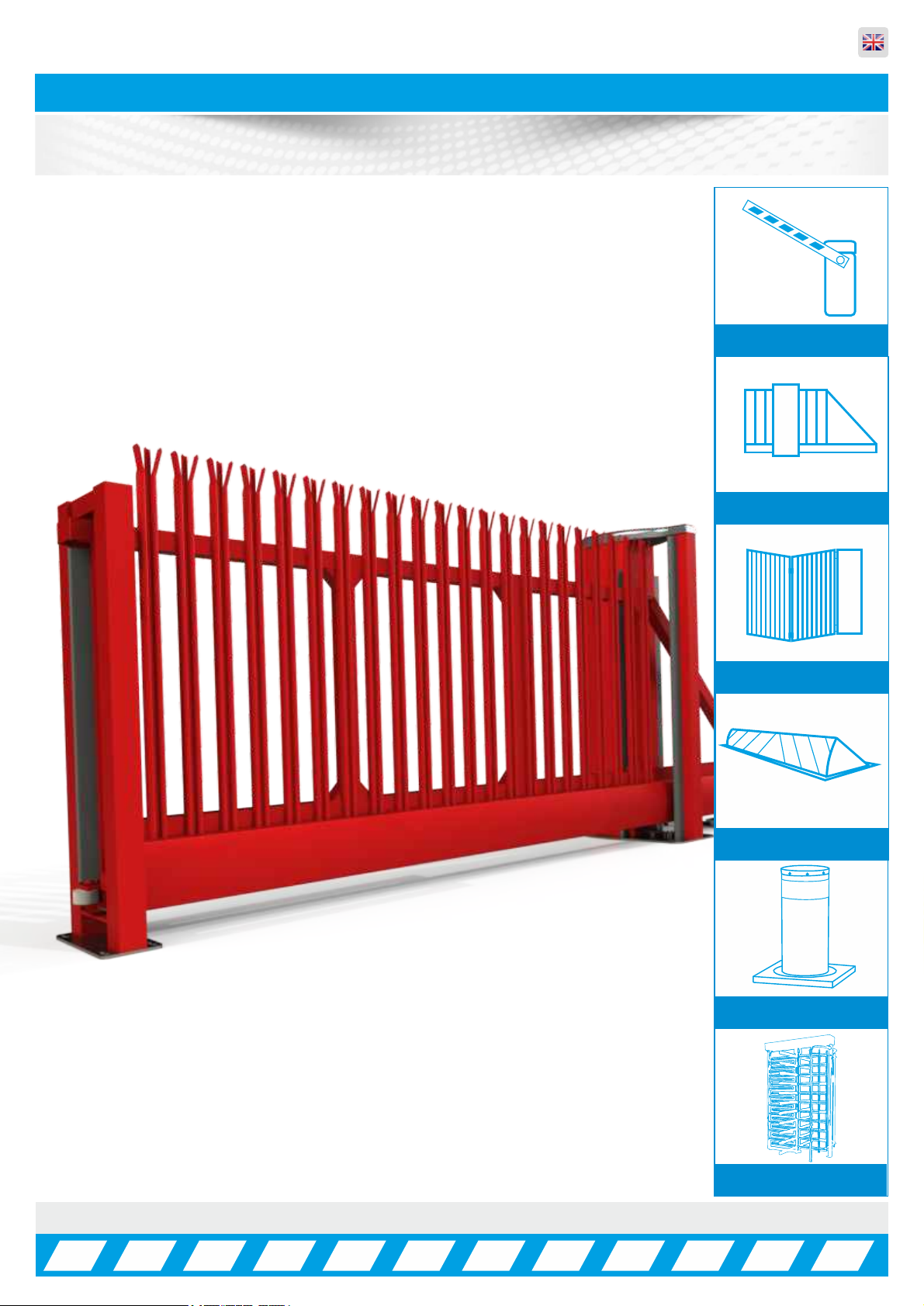
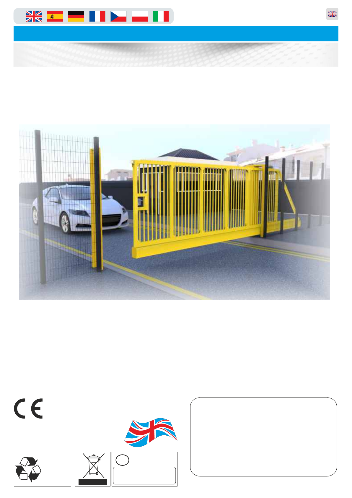
PF9000 Automatic Sliding Gate
Installation, Operation &
Maintenance Manual
Rev:7.5
Manual Barriers
Auto Sliding Gates
Auto Bi-Fold barriers
Auto Rising Kerbs
Auto Rising Bollards
Turnstiles
Page 2
in
Automatic Sliding Gates
INDEX ... Page No:
HEALTH & SAFETY INFORMATION 03
DELIVERY, MOVEMENT & TRANSPORT 04
COMPONENT IDENTIFICATION 05 - 07
PLC TIMER PROGRAMMING 08
OPENING & CLOSING POSITIONS 09
GATE USAGE 10 - 11
Parking and access control equipment manufactured in the UK
PARAMETER LIST 12
TROUBLESHOOTING GUIDE 13 - 14
WIRING DIAGRAM 15
QUICK CONNECTION GUIDE 16
MASTER/SLAVE WIRING 17
WIRING & PROGRAMMING 18 - 19
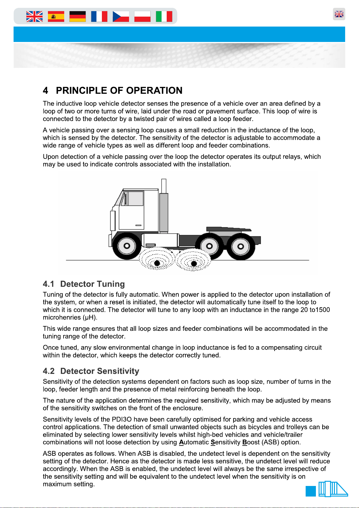
LOOP DETECTOR SETTINGS 20 - 21
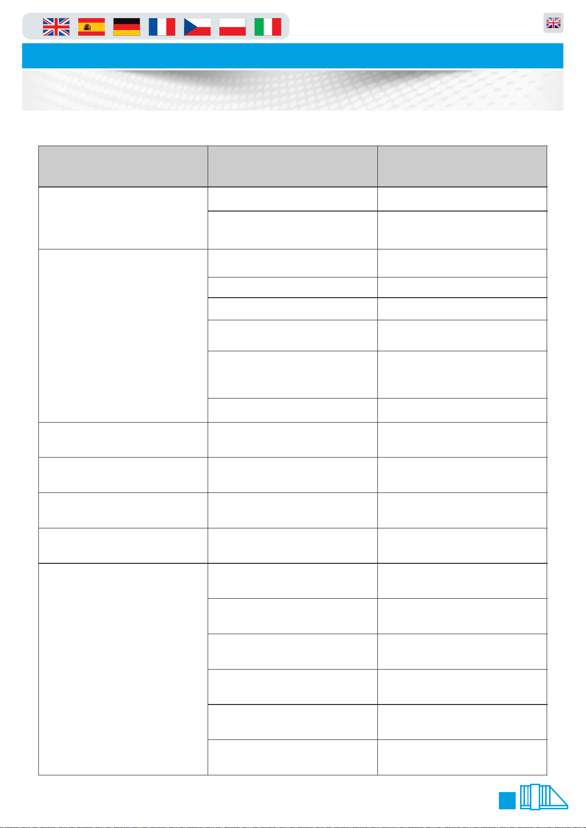
TROUBLESHOOTING GUIDE 22 - 23
POTENTIAL SYSTEM HAZARD AREAS 24
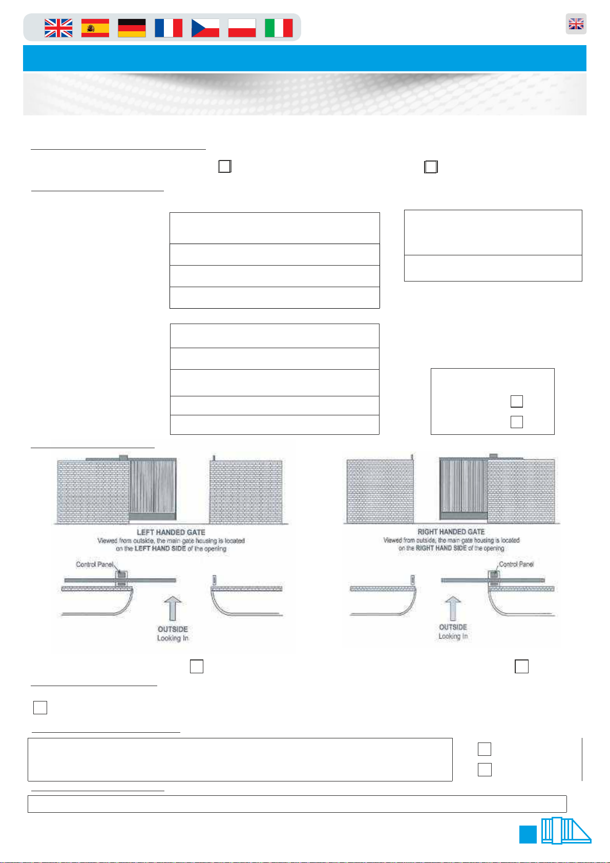
HANDING FORM 25
INSTALLATION & COMMISSIONING CHECK LIST 26
SERVICE LOG 27
COMMISSIONING CERTIFICATE 28
DECLARATION OF INCORPORATION 29
ELECTRONICS CERTIFICATE 30
NOTES 31
2
Page 3
in
Parking and access control equipment manufactured in the UK
Automatic Sliding Gates
Introduction and Warnings
This equipment is part of a large range of traffic flow products. They are designed to be easy to install, as
all settings and internal wiring has been completed in our factory. Any of the instructions in this manual
should only be carried out by a qualified service engineer or a competent person.
The gates are ready to bolt down, connect in the single phase supply and any loops etc and then power
up. In this manual there is important information on how to do this, but most importantly of all how to do
this safely. Please approach any task responsibly and safely.
The following information is a guide only, and whilst we have made every effort to be accurate and correct
there may be printing errors which we cannot be held responsible for.
With a correct installation you can expect to enjoy many years of reliable service from this product, we do
however recommend that the product has a bi-annual service carried out by an engineer. Please contact
our service department to obtain a quote. As we manufacture the products we are best suited to care for
your equipment.
Thank you for your custom and welcome to the exciting world of Total Traffic Flow Solutions.
Important Safety Notice
!
Sliding Gates are designed to Control the flow of vehicular traffic
primarily. It can be dangerous to allow the passage of
pedestrians and any other self-powered animal or device to
utilise this method of access without appropriate warnings and or
signage.
It may be necessary for the end user of this product to provide
an alternative, safe method of access to cater for the previously
mentioned categories.
The end user should fit all necessary signage and warning
notices to either side of the gate, which should be visible and
clear from all directions of approach.
The product that was shipped to you was designed with a control
program to protect all categories from harm or affect this
however is only a fail safe and should not be modified or
tampered with by any unauthorised person not sanctioned by the
manufacturer.
Please sign and date below to say that you have read and
understood this notice before ANY installation work:
/ /20
Information on using
this manual
Ÿ Read all information thoroughly
Ÿ Pay attention to all safety advice
Ÿ Be aware of the symbols (shown above right and
above left) as they have different meanings. One is an
information symbol, the other a warning.
Ÿ There are many artists impressions of the product in
this manual you should refer to the images as a guide
only. Professional CAD drawings should be used as
a reference drawing and nothing else. As before every
effort has been made to be 100% accurate in this
manual but we cannot make any guarantees.
Ÿ As we constantly innovate our products we may
change the quoted spec and any other details that
have been documented in this manual so you should
always refer to the supplier to see if the manual that
was shipped with your product is the latest edition.
Ÿ As with all electrical installations you should use a
qualified electrician and obey all of the latest laws and
regulations.
Ÿ Be sure to fill out and complete ALL paperwork where
instructed as this manual is the equipments log book
and maintenance manual.
The “Warnings” leaflet and “Instruction booklet” supplied with this
product should be read carefully as they provide important information
about safety, installation, use and maintenance.
Scrap packing materials (plastic, cardboard, polystyrene etc) according
to the provisions set out by current standards. Keep nylon or polystyrene
bags out of children's reach.
Keep the instructions together with the technical brochure for future
reference.
This product was exclusively designed and manufactured for the use
specified in the present documentation. Any other use not specified in
this documentation could damage the product and be dangerous.
The Company declines all responsibility for any consequences resulting
from improper use of the product, or use which is different from that
expected and specified in the present documentation.
Do not install the product in explosive atmosphere.
The construction components of this product must comply with the
following European Directives: 89/336/CEE, 73/23/EEC, 98/37/EEC
and subsequent amendments. As for all non-EEC countries, the abovementioned
standards as well as the current national standards should
be respected in order to achieve a good safety level.
The Company declines all responsibility for any consequences resulting
from failure to observe Good Technical Practice when constructing
closing structures (door, gates etc.), as well as from any deformation
which might occur during use.
The installation must comply with the provisions set out by the following
European Directives: 89/336/CEE, 73/23/EEC, 98/37/EEC and
subsequent amendments.
Disconnect the electrical power supply before carrying out any work on
the installation. Also disconnect any buffer batteries, if fitted.
Fit an omnipolar or magnetothermal switch on the mains power supply,
having a contact opening distance equal to or greater than 3mm.
Check that a differential switch with a 0.03A threshold is fitted just before
the power supply mains.
Check that earthing is carried out correctly: connect all metal parts for
closure (doors, gates etc.) and all system components provided with an
earth terminal.
Fit all the safety devices (photocells, electric edges etc.) which are
needed to protect the area from any danger caused by squashing,
conveying and shearing, according to and in compliance with the
applicable directives and technical standards.
3
Page 4
in
Parking and access control equipment manufactured in the UK
Automatic Sliding Gates
Delivery, Movement & Transportaton
This article describes how your equipment will be delivered to you, specifications on the transportation
used and advice including health & safety on movement of the equipment.
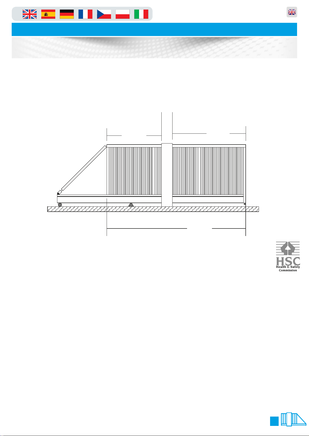
The gate should ALWAYS! be in the central position before any movement commences, this ensures that
the gate does not distort or get damaged. Refer to Manual Release instructions on Page 6 of this manual
to move the gate into this position.
Illustration shows gate central to main tower
37
7
50
94
The manufacturer will use a qualified transport company to deliver the product conforming to the
necessary regulations as detailed below:
Ÿ All drivers are qualified hi-ab certified
Ÿ All drivers are tested once yearly
Ÿ All drivers carry risk assessments and method statements (available on request)
Ÿ They are controlled under law to conform as there are no trade regulation standards to comply with
Health and safety Considerations:
Moving Goods Safely (MGS) is a national project involving both the Health and Safety Executive (HSE) and
Local Authorities (LA) working in partnership. The project aims to reduce injuries and ill-health arising from the
movement of goods from supplier through haulier to the recipient and end user including any home deliveries.
The project will focus upon the delivery and collection of goods and the hazards this generates. It covers the
main areas that cause the majority of injuries and ill-health to workers, including:
Ÿ Workplace transport;
Ÿ Slips & trips, and;
Ÿ Musculoskeletal disorders (MSD).
The movement of goods presents us, as health and safety regulators, with the challenge of dealing with a huge
variety of issues. The commercial organisations involved within the movement of goods are diverse including
haulier, third party logistics providers, pallet networks, retailers etc, with some very large companies,
thousands of small businesses and the self-employed. The movement of goods is more than just trucks on the
road with a large proportion of accidents happening at the delivery/collection sites that are often not directly
under the control of the company making the delivery or collection. Communication and cooperation problems
can arise due to the many organizations involved in the movement of the goods, and this can also lead to
difficulties in effectively managing health and safety.
(Source H&S Executive UK 2008)
4
Page 5
in
Parking and access control equipment manufactured in the UK
Automatic Sliding Gates
Component Identification & Notes
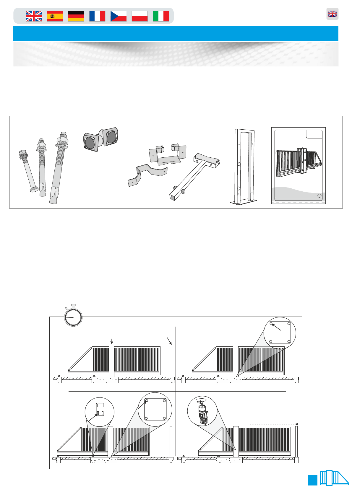
You should check that you have received the following in your order as they are referred to throughout this
manual (note this can change per gate spec i.e. manual components are different from automatic):
O&M Manual 1 No.
O&M Manual
Revision 3.0
PF9000 A/M
PF9000 A/M
Automatic Sliding Gate
Manual Sliding Gate
Maximum Span: 10 Metres
Duty Cycle: 100%
GB
M16 Anchor
Catch Post
Bolt 4 No.
M16 Bolt
8 No.
M20 Bolt
4 No.
Photo Cells for
catch Post 2No.
Top catch post
bracket 1 No.
Bottom catch
post bracket 1 No.
Rear external
roller 1 No.
Catch post 1 No.
The numbers in the text document below relate to the drawings below.
1. When delivered, the gate is locked in a central position so that the gate is
balanced when lifted from the top of the tower.
2. Lower the gate onto the plinth and visually align the gate and catch-post into position. Using one M20
fixing, bolt down the main tower using one of the rear bolt-down holes.
3. Making sure that the gate is still visually aligned, use one M16 fixing and bolt down the rear support
wheels (on the opposite side to the hole used on the main tower) see below.
4. Manually slide the gate into the closed position to fine tune the alignment of the gate with the catch
post.(See Page 6 for details on Manual Release)
60
5
55
10
50
45
40
1. 2.
3.
45 mins
15
20
35
25
30
Lifting Point
Catch Post
4.
5
Page 6
in
Automatic Sliding Gates
Parking and access control equipment manufactured in the UK
Component Identification & Notes
5/6.
9.
Beam shown
to be level
Spirit Level Co.
7/8.
10/11.
30mm Nut
30mm Nut
Central Position
Receiver
Transmitter
45 mins
55
50
45
40
35
Transmitter
Receiver
60
5
10
15
20
25
30
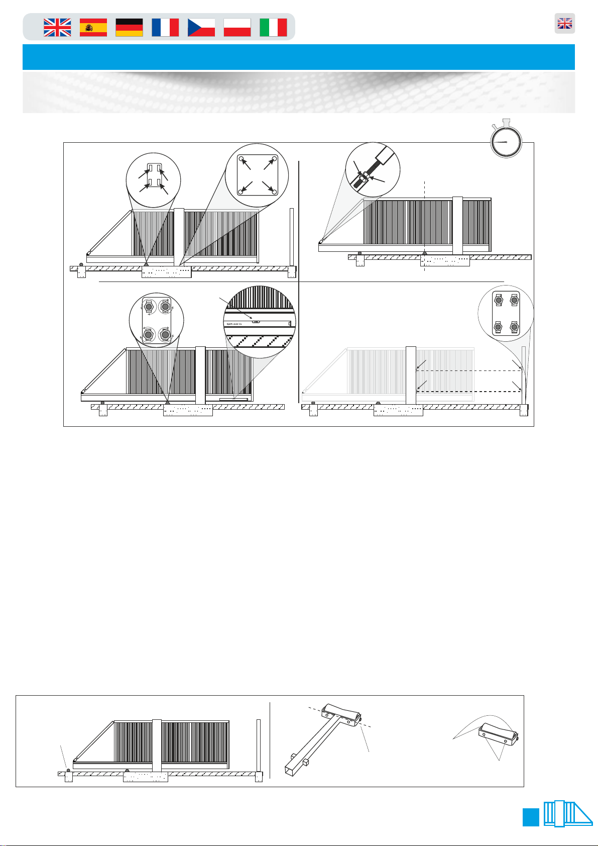
5. Manually slide the gate back into the central “balanced” position taking care
not to move the tower or rear wheel support base plate.
6. Finish bolting down the rear support wheel base-plate and the main tower of the gate
making sure that it is true and square in both directions.
7. Slide the gate until the centre of the lower main beam is in the centre of the rear support wheels and the
centre of the main tower i.e. have the lower main beam supported centrally by the rear support wheels
and the drive rollers.
8. Undo the 30mm nuts that lock the cantilever arm adjuster to relax the cantilever arm and leave the gate
in an unstressed state.
9. Placing a level on the centre of the lower beam or lower rail, adjust the rear wheel support until the
lower main beam is level. Manually pull the gate closed and adjust the cantilever until the gate is level.
10. Using a laser square or similar, make sure the photo-cells from the Main Gate Housing to the Catch
Post line up (this should be already level as it is governed by the plinth levels).
11. Now fit the two photo cells provided in the pre drilled holes and connect using the wiring diagram
(page 8). Once the Photo Cells have been connected, complete the installation of the Catch Post using 4
x M16 fixing bolts (supplied) making sure that it is true and square.
12. Now most important of all, you must fit the rear roller as shown (under the parts list on the previous
page), which is universal in the way it can be fitted. It can either be used as a “cast in” post, or the bottom
strut can be cut off and used as a “bolt down” roller all illustrated below.
12.
Before you can bolt
Bolt down or cast
the rear roller in this
position shown.
Cut along this line to
remove the bottom
spiggots and shaft.
the part down you
have to remove this
roller by un-doing
the nuts either side
as shown.
Once the shaft is
removed you will
use the M16 bolts
to fix down.
6
Page 7
in
Parking and access control equipment manufactured in the UK
Automatic Sliding Gates
Manual Operation & Maintenance
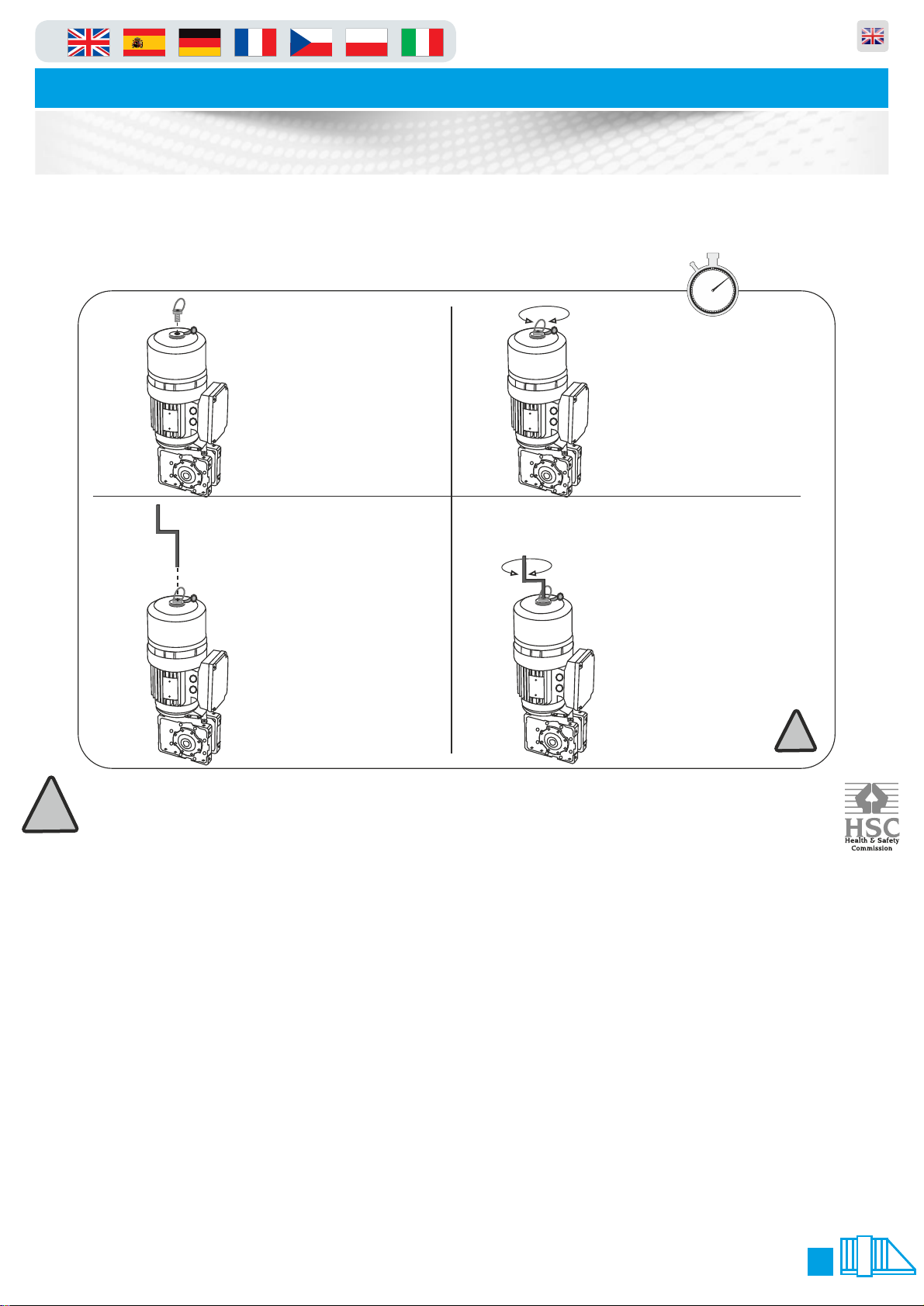
Please use the following instructions to operate the gate manually, the following
is assuming you have powered down the unit and opened the main tower door:
1.
Remove the dust cover plug
then get the brake release key
from its holder in the cabinet
and insert it into the top of the
motor.
2.
Keep pushing with a
downwards pressure and
turn clockwise to screw
into the hole which will
release the brake. Do
this until you feel it is
hand tight.
60
5
55
10
50
45
40
35
10 mins
15
20
25
30
3.
Remove the release key
from holder on the door
then insert the release
key in the exposed hole.
4.
Now the Key is inserted fully
into the top hole turn
clockwise to open and anticlockwise to close. After this
you must remove the brake
key and replace the bung.
FAILURE TO DO THIS WILL
ALLOW DAMAGE THE
BRAKE/MOTOR AND THE
GEARBOX. !!!!!! THIS IS VERY
IMPORTANT!!!!!!
!
IMPORTANT NOTE
!
In order for the equipment to comply to the legislation/directives noted in this document it must be
maintained and have a maintenance schedule as documented in Regulation 5 of “The workplace health &
Safety Welfare Regulations 1992"
As stated at the beginning of this manual we recommend a bi-annual service, but at a bear minimum, it is
imperative that you get a service done once every 12 months. This is not a sales tactic in disguise, there is
a very serious health and safety issues/risks associated with not complying to this. Also in order for your
gate to keep complying with the appropriate legislation.
Ÿ Before carrying out any maintenance to the installation, disconnect the mains power supply.
Ÿ Make sure you have disconnected/Isolated the power before attempting any work.
Ÿ A Maintenance Contract should be sought from a specialist company after a maximum of 5000 manoeuvres or 1year from
the install date.
Ÿ Occasionally clean the photocell optical components and make sure they are free from dirt, water, rain, soil etc..
Ÿ Have a qualified technician (installer) check the correct setting of the electric clutch.
Ÿ If the power supply cable is damaged, it must be replaced by the manufacturer or its technical assistance service, or else by
a suitably qualified person, in order to prevent any risk.
Ÿ When any operational malfunction is found, and not resolved, disconnect the mains power supply and request the
assistance of a qualified technician (installer). When automation is out of order, activate the manual release to allow the
opening and closing operations to be carried out manually.
Ÿ Gearbox drive unit is “sealed” for life and requires no further lubrication.
7
Page 8
in
Automatic Sliding Gates
PLC Timer Programming
If you have a PLC timer fitted
then please use the guide
below:
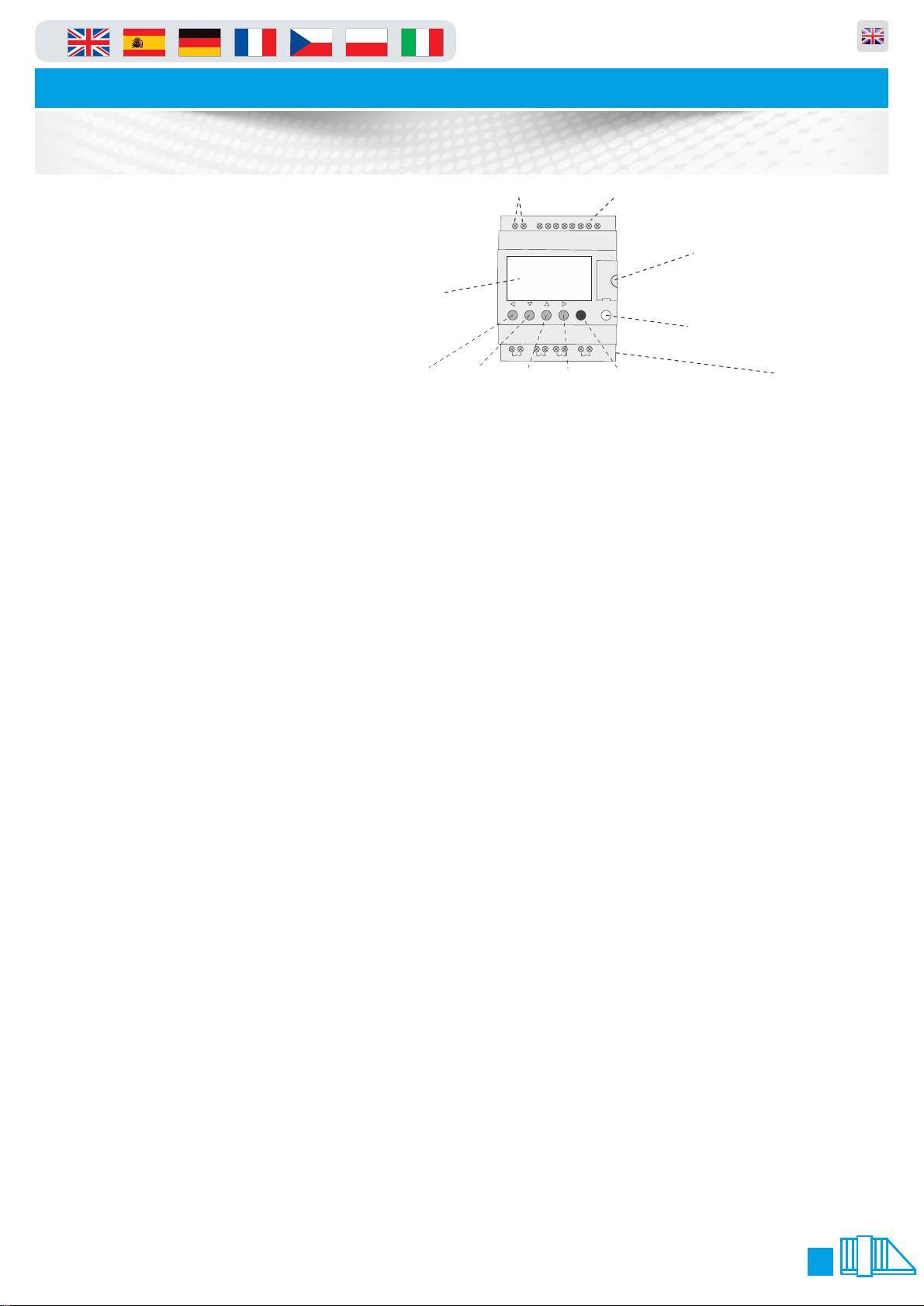
3.1 Run and Stop modes
The Zelio PLC has two modes: run mode and stop mode. These are selected
via the Zelio front panel by pressing the MENU/OK button, scrolling with the
arrow keys to RUN/STOP and pressing MENU/OK again. Run is the normal
operation mode. When Stop mode is selected, the PLC will ignore its inputs and
no outputs will be activated.
Note: When run mode is selected via the menu, the choice of initialising
the non volatile memory in the PLC is given. If the option to initialise
the memory is selected (“WITH NONVOLAT INI”), changes made to
the configuration using the custom menu system described in section
3.4 will be reset to default values. However, changes made via the
parameters menu as described in section 3.2 will not be reset.
It is suggested that all normal configuration be done in run mode. This is
because the parameter menu is somewhat simplified in this mode, and the
custom menu system is only available when in this mode.
3.2 Configuring parameters via the parameter menu
Only an overview of using the parameters menu is given here. For details
consult the Zelio documentation, as the parameters menu is a standard feature
of the Zelio PLC. Only editing the parameters menu in run mode is described.
3.2.1 Accessing the parameters menu
The parameters menu is accessed by pressing the MENU/OK button, scrolling
with the arrow keys to CONFIGURATION, and pressing MENU/OK again. Once this
is done the first parameter (normally H1) will be displayed, with the cursor (i.e.
the flashing character) positioned near the top left of the screen on the
parameter number. Whilst the cursor is in this position (and only whilst in this
position), the up arrow will then cycle forwards through the list of available
parameters (i.e. H1, H2, TT1, TT2 ... TT7) and the down arrow will cycle back.
As this is done, the screen will change to show the relevant information for that
parameter. The diagram below shows a typical screen shot for clock parameter
H1, with the bold character showing the cursor position:
H1 ----4-B
H:M ON 12:16
H:M OFF 12:18
- 5 The right and left arrows will move between the various parts of the screen
that can be altered (see details below). When the cursor is in any position other
than the top left, the up and down arrows alter the value that the cursor is
currently over.
After altering a value with the up and down arrows, pressing MENU/OK or trying
to move to a different parameter (by going to the top left and pressing up or
down) will result in a message asking for confirmation of the changes – use the
Parking and access control equipment manufactured in the UK
LCD Screen
Z1 (Left) Z4 (Right)Z3 (Up)Z2 (Down)
Power
Inputs
+ -
24VDC
Outputs
Q1...Q4 : Relay 8A
2
1
Q1
I1 I2 I3 I4 IB IDIC IE
24VDC 24VDC
Menu/Ok
2
2
1
1
1
Q2
Q3
IB....IEInputs I1...I4
Analog or
Q4
2
SR2 B121BD
Inputs
Menu/Ok
(green)
Memory card
slot
White “Shift” button to press & hold
whilst using arrow keys to change values
Outputs
8
Page 9
in
Parking and access control equipment manufactured in the UK
Automatic Sliding Gates
Opening & Closing Positions
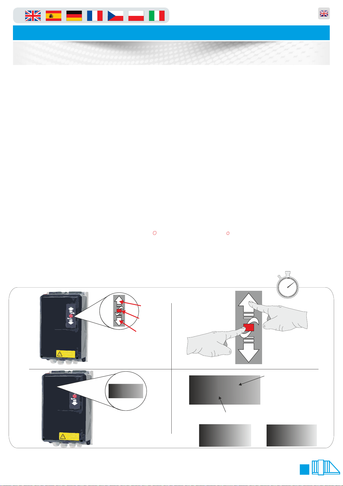
When you first turn the gate on you will need to calibrate the gate, this in laymans terms means teaching
the open and close positions. You can also follow this guide should you need to re-teach the positions in
the future.
1. Enter the menu following the guide on page 9
2. Go to make sure that this is set to value this tells the gate to auto learn new settingsP.216 2
3. Now go to and change the value to P.210 5
4. Exit the menu and the display will show C.A.L.I.
5. Press the “stop” button the dots at the bottom of the screen will now flash
6. The screen will display “e.i.e.u”
7. Using the “down” arrow move the gate to the close position double check and move to step 8 (you have
to hold the button in to move similar to deadman mode)
8. Now you are happy with the close press and HOLD the stop key for 3 seconds to save the position
9. Now the display will change to “e.i.e.o”
10. Using the “up” arrow move the gate to the open position double check and move to step 11 (you have
to hold the button in to move similar to deadman mode)
11. Now you are happy with the open press and HOLD the stop key for 3 seconds to save the position
12. The display will show this denotes that the gate wants to run backward and forward to learn the i.555
torque settings and braking distances etc. To complete the learning process just keep pressing the up
and down arrow unit the display shows when opening and when closing. The calibration ope cls
/Learning is now complete.
13. Now you must enter the menu and change back to value and save, this inhibits the gate from p.216 1
self learning and settings thus keeps the positions you have taught in.
1. 2.
STOP
UP ARROW
STOP BUTTON
DOWN ARROW
figure.1
4.3.
P.999
figure.3
figure.5
.0.99
figure.4
‘STOP’
STOP
LED Dot
Normal State = Static
Changed State = Flashing
60
5
55
10
50
45
40
35
figure.2
10 mins
15
20
25
30
LED Letters
or numbers
‘AU’
9
Page 10
in
Automatic Sliding Gates
Gate Usage
Parking and access control equipment manufactured in the UK
Mobil Safety
(Closing)
4x Stationary Safety
(Opening and Closing)
Mobil Safety
(Opening)
Optional
8K2
8K2
TST FSAM
RS485
<->
USB
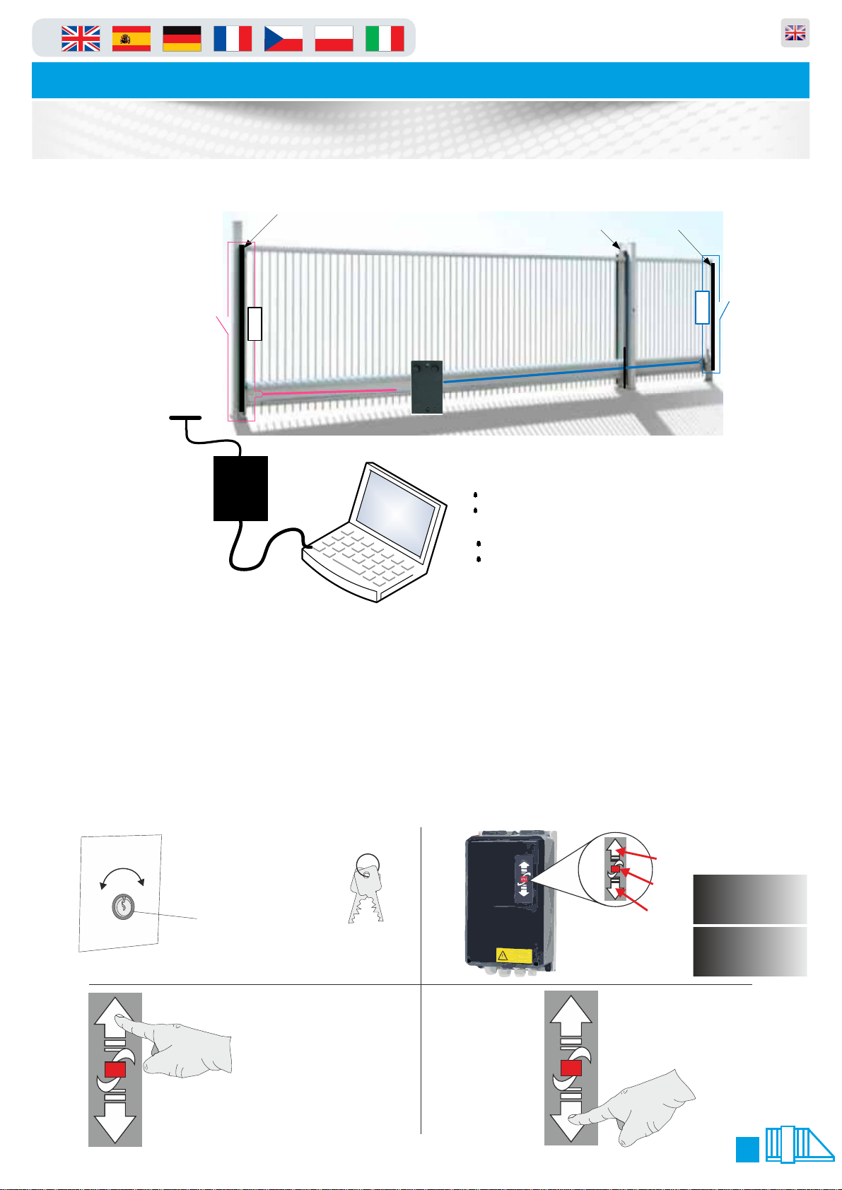
There are many options to operate the gate and is dependant upon which type of access control you have connected.
However there is a standard way to operate the gate by using the key switch and the arrows on the front of the panel
Instructions are assisted by pictures below.
1. Picture shown below is the key switch (if fitted) which is located on the outside of the gate cabinet (it will always
be on the opposite side to the gate arm, also picture shows the key switch keys.
2. To move the gate using the arrow keys on the panel first make sure the screen says “-e.o-” (end position open)
or “-e.c-”(end position closed) if it does not follow the troubleshooting guide on page 11 when the screen does say
“-e.o-” or “-e.c-” follow below.
3. To make the gate move to “open” press the up arrow.
4. To make the gate move to “close” press the down arrow.
Please note that the step 4 manoeuvre will not work if there is something in the way of photocells a presence on the
loops.
TST Toolbox
Parameter update
Diagnose
Software update
Update Controller
Update WiCab
This key switch is mounted on
1. 2.
Auto
Open
3.
STOP
the side of the gate
Key switch
Drawing showing the “UP”
arrow being pressed
IDEC
IDEC
Key switch
keys
4.
STOP
STOP
UP ARROW
STOP BUTTON
DOWN ARROW
-e.c-
-e.o-
Drawing showing the “DOWN”
arrow being pressed
10
Page 11
in
Automatic Sliding Gates
Gate Usage
1. 2.
STOP
UP ARROW
STOP BUTTON
DOWN ARROW
Parking and access control equipment manufactured in the UK
60
5
55
10
STOP
50
45
40
35
10 mins
15
20
25
30
figure.1
figure.2
LED Letters
4.3.
P.999
figure.3
figure.5
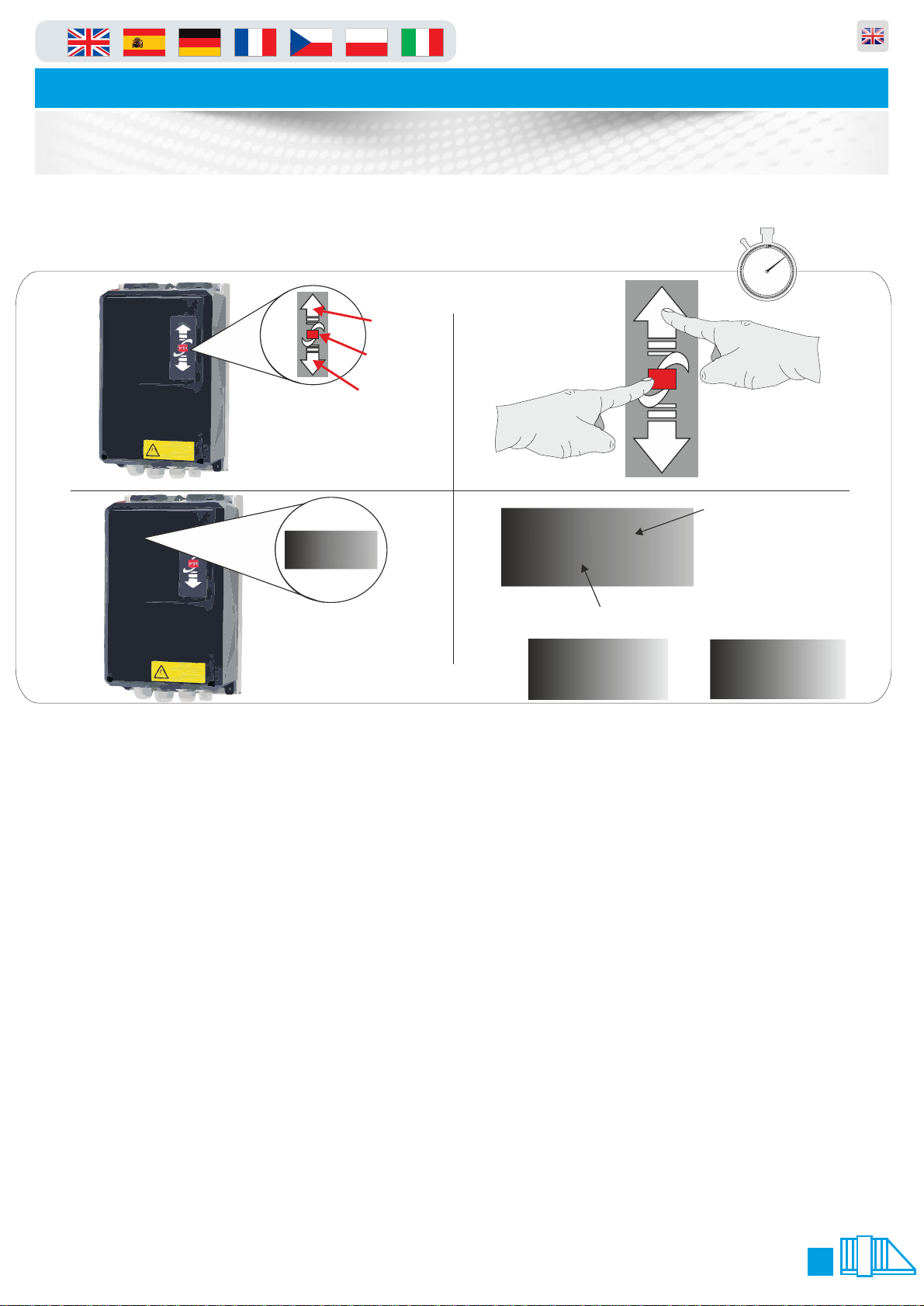
1. 1. On the front of the panel locate the function buttons (figure.1)
2. 2. Press and hold the “up” arrow and “stop” button together for 3 seconds (figure.2).
3. The LCD display and change to P.000 or P.xxx (xxx will be a parameter number last used) you are now
in programming mode and can follow the next line of instructions. When finished and to exit programming
mode press and hold the stop button for 5 seconds.
Scroll to P.999 and press the STOP button This will display “0001" change this to “0003" and press and
hold stop until the dots stop flashing under this text. Then press and release STOP button again to exit
that parameter.
4. To enter a parameter scroll using the arrow keys until the LCD display show the number you require
(figure.3) using the command buttons (figure.2). when the display shows the parameter number required
in the first column of the table below, press the STOP button for one second. You are now in that selected
parameter, should you wish to leave this parameter or discard any changes simply press the STOP button
again for 1 second ONLY!!. To make any adjustments in the selected parameter simply use the arrow keys
(figure.2) up or down, when the appropriate value is selected you should press and hold the STOP button
until the flashing dots between the value cease to flash (see figure.4). The value you selected has now
been saved to memory. To exit the menu press and hold the “stop” key for seven seconds until the LCD
display shows “STOP” or “AU” (figure.5)
.0.99
figure.4
‘STOP’
LED Dot
Normal State = Static
Changed State = Flashing
or numbers
‘AU’
11
Page 12
in
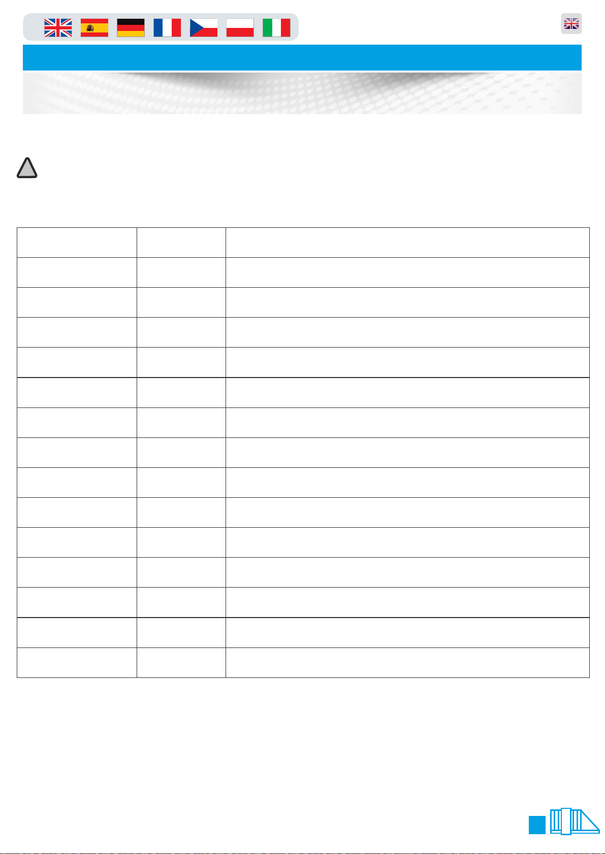
Parameter Number
Change to
What this parameter does
P.991
0200
Tells the panel it is connected to a gate
P.990
1
Sets the gate back to default WARNING!
P.802
0302
Activates Plug in loop Detector IF YOU HAVE ONE FITTED
P.702
0801
Set Output 2 to release the brake on the motor
p.507
0501
Enables the top photocells
p.506
0501
Enables the bottom photocells
p.450
300
Increases the lag error detection time
p.438
50
Increases the rotation direction error time
p.352
15
Speed for start of close
p.350
25
Speed for close
p.312
15
Speed for start of open
p.310
25
Speed for open
p.216
1
Prevents the gate re-learning it own parameters.
p.F00
0
Turns off Wireless Safety Edge System
Parking and access control equipment manufactured in the UK
Automatic Sliding Gates
Parameter List
!
Please note you DO NOT need to use these unless you have a problem!!
1. Follow the guide on page 10, to enter the menu.
2. Scroll to parameter P.990 change the value to 1 (this will default the panel to factory default)
3. Continue to change the parameters to the values below.
!! P.216 Must be set to “1" when calibration has finished
12
Page 13
in
Message
Short description:
Cause of message
Automatic Sliding Gates
Parking and access control equipment manufactured in the UK
Troubleshooting Guide
F.020
F.030
F.031
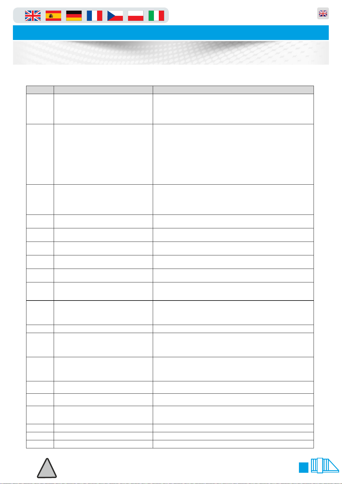
ĞBČĈĈ External E-Stop 1 tripped • E-Stop chain was interrupted starting at Input 1
Run time exceeded (during opening,
closing or deadman)
Lag error (position change of the
door is less than expected)
Detected rotational direction
deviates from expected
• current motor run time has exceeded set maximum run time
(P.410 (Opening), P.415 (Closing), P.419 (Deadman move)), door
may be sticking or is blocked
• Door is blocked
• If using mechanical limit switches, one may not have tripped
• gate or motor is blocked
• insufficient power for providing necessary torque
• too little speed
• mechanical limit switch was not left or is defective
• Incremental or absolute encoder shaft is slipping
• wrong positioning system selected (P.205)
• one motor phase is missing
• the brake does not release
• Settings of the failure detecting time are not correct (P.430 or
P.450)
• When using incremental encoders: Channel A and B reversed
• Motor rotation direction reversed compared with calibration setting
? teach in the limits again (P.210 = 5)
• Too much „pancaking“ when starting, brake releases too soon, or
too little torque, adjust boost (P.140 or P.145) as necessary.
F.212 External E-Stop 2 tripped • E-Stop chain was interrupted starting at Input 2
F.320 Obstacle during opening • During opening an obstacle has recognized
F.325 Obstacle during closing • During closing an obstacle has recognized
F.360 Short circuit detected on edge input • Short circuit detected on edges with normally closed contact
• Excessive noise on supply voltage
C ﻰﮭ ﮭ
F.410
F.425
F.510
F.520
F.521
F.525
F.530
F.535
F.700
F.930
Controller hardware reset detected
Over-current (motor current or DCbus)
Overvoltage line supply
Motor / DC-bus overcurrent Limit 2
Overvoltage in DC-bus Limit 2
Overvoltage in DC-bus
Overvoltage at the line supply input
Heatsink temperature outside of working
range Limit 1
Housing temperature high • The temperature inside the controller housing is to high
Impossible combination of Limits
External watchdog incorrect • Defective hardware has been damaged by water or electric
• Internal watchdog tripped
• RAM error
• Wrong motor data set (P.100 – P.103)
• Non-adjusted voltage increase / boost set (P.140 or P.145)
• Motor not properly dimensioned for door
• Door sticks
• The supply voltage for the controller is to high
• Wrong motor data set (P.100 – P.103)
• Non-adjusted voltage increase / boost set (P.140 or P.145)
• Motor not properly dimensioned for door
• Door sticks
• Brake chopper interference / defective / missing
• Feed voltage much to high
• Motor feeds back too much energy in generator mode, door
motion energy cannot be sufficiently brought down.
• Input voltage supply too low, usually at load
• Load too great / final stage or brake chopper fault
• The line supply for the Controller is to high
• The line supply fluctuates very extremly
• Excessive load on final stages or brake chopper
• Ambient temperature too low for controller operation
• Clock frequency of final stage too high (Parameter P.160)
• Both limit switches are active at the same time
!
!
Please note:gate moves only in “dead-man” mode if you have any of the messages
Please note:gate moves only in “dead-man” mode if you have any of the messages
marked above (with this symbol:*) shown on the display
marked above (with this symbol:*) shown on the display
13
Page 14
in
Message
Short description:
Cause of message
Automatic Sliding Gates
Troubleshooting Guide
Parking and access control equipment manufactured in the UK
I.080
I.100
I.150
I.160
I.161
I.170
I.180
I.199
I.200
I.201
I.205
I.210
I.211
I.200
I.205
I.310
I.320
I.325
I.360
I.363
I.510
I.515
I.520
I.555
E.000
E.050
E.090
E.101
E.102
E.103
E.104
E.105
E.106
E.107
E.108
E.211
E.360
E.501
E.502
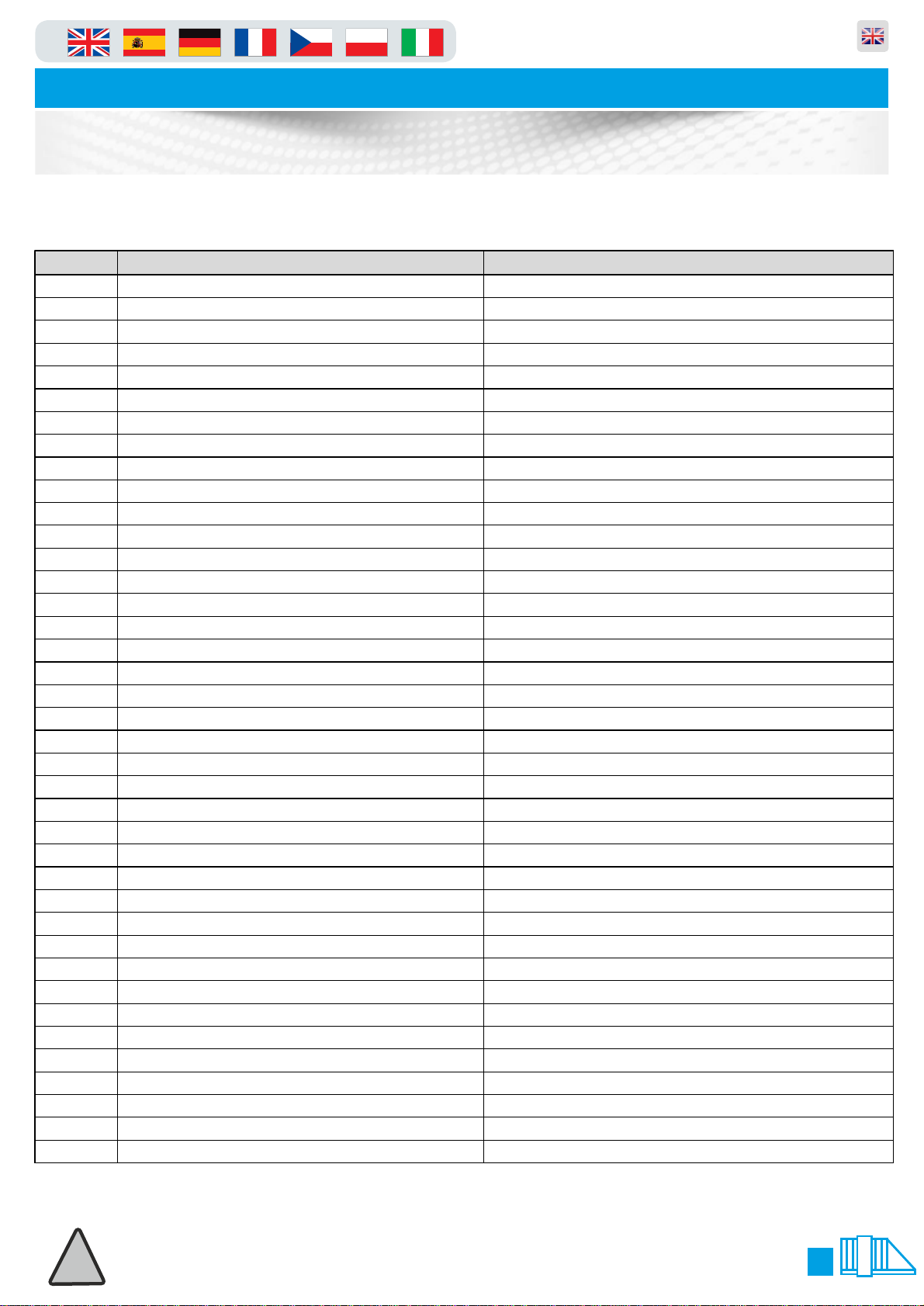
Service counter will run off
Speed in open position to high
Speed in close position to high
Permanent open command still active
Priority not active
Forced opening active
Wait for foil key command
Door counter wrong
New reference position taken over
Reference position new initialized
Synchronisation done
Limit switch not plausible
Limit switch not plausible
Reference corrected
Reference position encoder
Open command to door 2
Obstacle during opening
Obstacle during closing
Disturbed N.C. safety edge
Disturbed N.O. safety edge
Correction drive finished
Active correction drive
Pre set speed for open or close drive not reached
Measuring rotation factor not ready
ÀÎ ŐÑŌ on Keypad pressed"
ÀĬ PŎŐ on Keypad pressed "
ÀFÕŎŒÑ on Keypad pressed "
ÀHŌŐÞP Ĉ active"
ÀHŌŐÞP Č active "
ÀHŌŐÞP Ċ active "
ÀHŌŐÞP Ç active "
ÀHŌŐÞP D active "
ÀHŌŐÞP Ď active "
ÀHŌŐÞP Đ active "
ÀHŌŐÞP Ð active "
ÀE-Stop Ext"
Stuck button or cable not connected correctly
Stuck button or cable not connected correctly
Stuck button or cable not connected correctly
Permanent Stop Signal
Permanent Open Signal
Permanent Close Signal
Lower “close” limit has made
Upper “open” limit has made
Photo-Cell or other safety device active
Photo-Cell or other safety device active
This input has been activated by connected device
Barrier door safety switch open*
ÀSafety Edge Tripped" CĂĵ ▄ĊŦ ℓ ĂźśĊŦ śŕ ┼ś ◘ʼn śŕ ┼ś ╜ℓ Ľś╜■┼ ♫ʼnśℓ ℓ śŕ *
ÀI ŎŎŐ FOĈÀ
ÀI ŎŎŐ FOČÀ
Presence on safety loop “Channel 1”*
Presence on auto loop “Channel 2”*
Please note:gate moves only in “dead-man” mode if you have any of the messages
!
marked above (with this symbol:*) shown on the display
14
Page 15
in
Automatic Sliding Gates
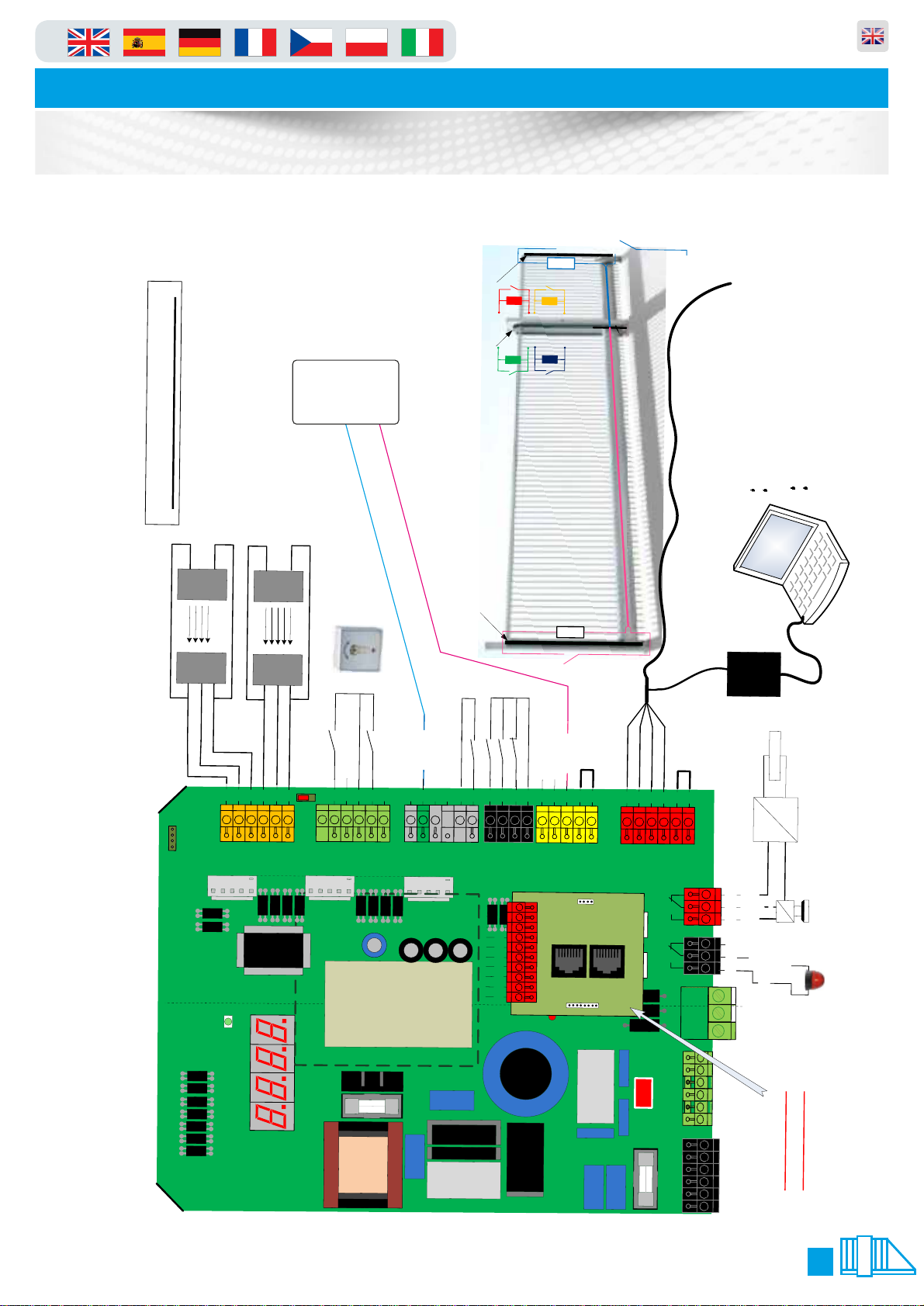
Wiring Diagram
Parking and access control equipment manufactured in the UK
8K2
ening)
il Safety
(Op
Mob
d Closing)
To Encoder
Relay
Safety
ASO
4x Stationary Safety
(Opening an
Gate P991 = 0200
Sending
Photo Eye
Sending
Photo Eye
(Closing)
Mobil Safety
8K2
Receiving
Photo Eye
6
5
4
3
e
s
d
o
l
a
c
p
p
y
o
e
t
k
s
-
l
i
n
o
e
F
p
O
D
N
E
U
L
R
8
V
4
2
+
2
8
8
8
8
V
D
7
6
N
4
N
N
2
I
I
G
+
Receiving
Photo Eye
1
8
.
m
m
a
r
g
o
r
D
P
N
-
G
P
I
D
an Switch
Deadm
e
s
o
l
C
.505 = 1502
P
5
4
7
7
V
D
5
4
N
N
2
I
G
+
n
e
p
O
.505 = 1501
P
3
2
7
7
V
4
4
N
2
I
+
n
e
n
p
e
s
e
o
p
o
t
p
l
O
S
C
O
n
a
i
r
t
s
Out 2
6
1
6
7
5
D
1
N
t
u
G
O
V
4
2
+
e
d
e
P
5
4
3
2
6
0
1
N
I
1
6
6
6
6
V
D
D
8
4
N
N
2
I
G
+
Out 1
4
3
2
1
5
4
3
2
1
6
5
5
5
5
4
4
4
4
4
i
2
e
D
L
-
N
i
G
S
Luminaire
1
1
1
A
A
N
N
RS485
V
V
2
3
1
4
2
N
N
N
2
I
I
I
1
+
+
1
2
3
4
5
6
7
8
9
10
5
3
3
D
N
B
G
O
u
t
2
CAN
O
u
t
1
TST RFUZ -COM
4
3
2
1
3
3
3
3
1
2
V
2
2
2
A
A
A
1
N
N
+
2
2
2
Out 2
Out 1
1
2
0
1
2
1
1
1
0
te
oolbox
Update Controller
Parameter update
Diagnose
TST T
Software upda
<->
USB
RS485
Brake
=
~
NC
1
L
=
N
NO
~
Link to
24+V
Link to
24-GND
+
3
T
2
T
1
T
Update WiCab
Brake
arning
Light
W
PE
N
N
N
1
L
1
L
L
l:
Contro
201 Master
200 Slave
= 0
A.820
A.820 = 0
Master Slave
Link Terminals 2,3,4 Only!
15
From Module Board
Page 16
in
Parking and access control equipment manufactured in the UK
Automatic Sliding Gates
Quick Connection Guide
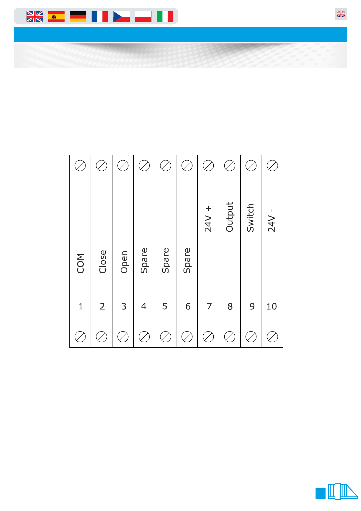
We have made the most common connections available without having to open the control panel cover
see below for info. Please NOTE that you will have to enable the corresponding parameters to activate the
inputs, as they are disabled in factory when testing the gates. The terminal block is GREEN in colour.
Photocell
NOTE
You Must enable the following parameters:
P.507 = 0501
P.506 = 0501
Photocell
Photocell
Photocell
16
Page 17
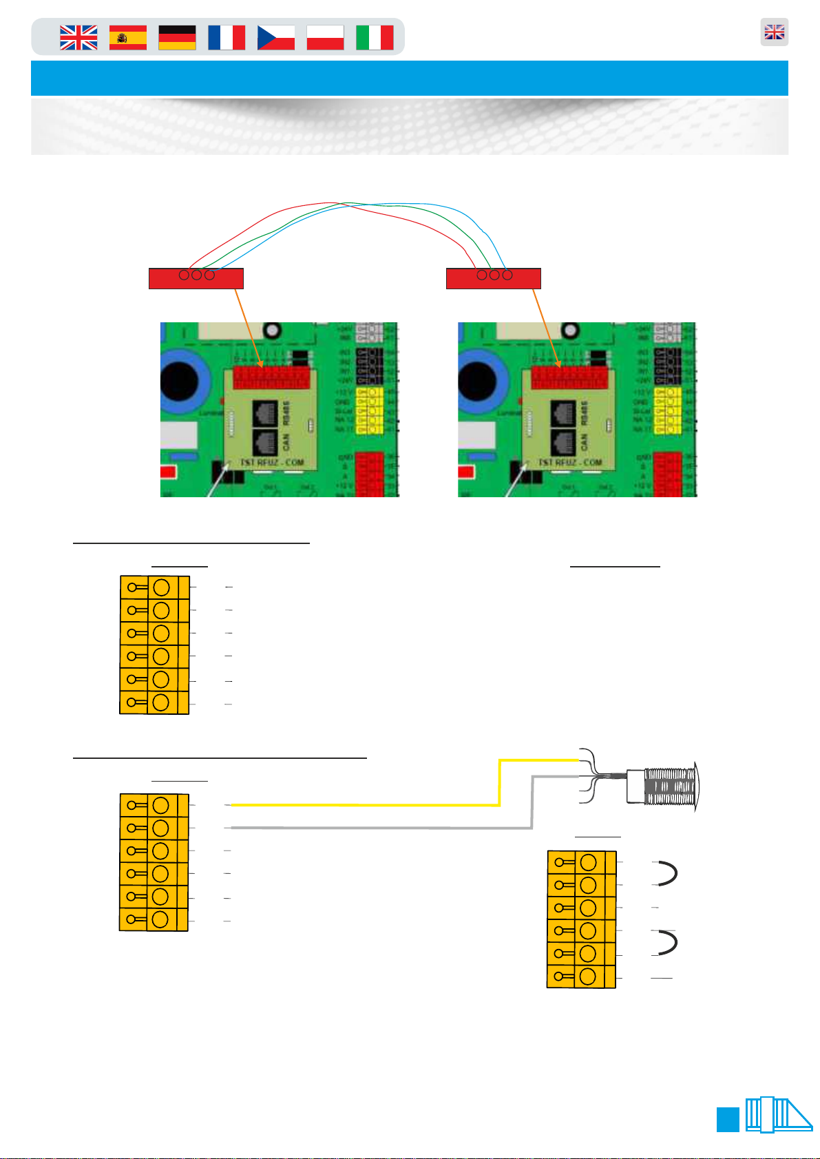
in
Automatic Sliding Gates
Master/Slave Wiring
Parking and access control equipment manufactured in the UK
3 wires only
3
4
2
Normal Photocell Wiring
Master
+
2
4
V
N
I
7
G
N
D
+
2
4
V
I
N
6
G
N
D
8
8
8
8
8
8
Yellow/Brown
6
Grey
5
Blue
4
Yellow/Brown
3
Grey
2
Blue
1
3
4
2
Catch Post
Wire to main panel IN 7
Terminals 86/85/84
Master/Slave Photocell Wiring
Master
8
+
2
4
V
N
I
7
G
N
D
+
2
4
V
I
N
6
G
N
D
6
8
5
8
4
8
3
8
2
8
1
Yellows from Slave Photocells
Greys from Slave Photocells
Blue
Yellow/Brown
Grey
Blue
Wire in Series to master
Terminals 85&86 Yellow
and Grey from slave
Link between terminals
85&86 and 82&83
Wire in Series
Slave
8
6
8
5
8
4
8
3
8
2
8
1
Link Out
85&86
Brown
Link Out
82&83
Blue
On Both Panels enable:
P.507=0501
P.506=0501
17
Page 18
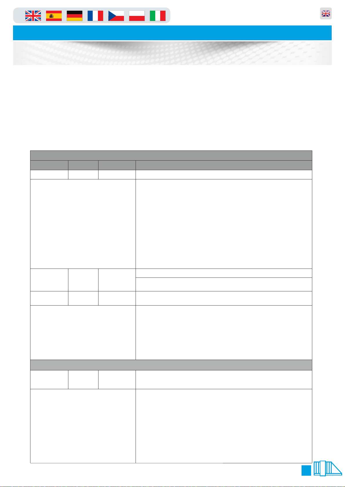
in
Parking and access control equipment manufactured in the UK
Automatic Sliding Gates
Wiring & Programming
Every input/output is highly configurable, and can be changed from its default/state use. The below is a
guide to what they can be changed to and the effect of this change. The logic behind this is as follows:
On the wiring diagram each terminal has an input number this is noted as “IN6" for example. To change
this or other values the table below quotes P. 0 the “ ” needs to be replaced with the input/output you 5x x
wish to configure. So as an example if we wanted to change input “6" (terminals 82&83) we would replace
the “ ” with “ " making it “P. 0". Also note that the number following “P.” (in our example “ ") denotes we x 6 65 5
are dealing with and “input” if instead we wanted to deal with an “output” we would replace the “ " with a 5
“ ". The below is a brief summary of common changes but there are MANY more options than listed here, 7
for a full list please contact the supplying company.
Inputs
Parameter Unit Range
P.5x0 0 ..... 18 Input Functions With this parameter the functionality for parameter x is set.
Notes Area...
P.5x2 0 ..... 1 Contact Type
P.5x4 0 ..... 7 Hold-open time /
Notes Area...
P.7x0 0 ..... 27 Switching
Notes Area...
Function Description/Value of Parameter
0: Input deactivated
1: OPEN command
2: Single channel / pull switch
3: Permanent open command
4: Stop command
5: Safety B
6: Jog mode / Automatic switch
7: Close command
8: Door locking in end position
9: Cross traffic input
10: Deactivation input
11: Limit switch input
14: Safety A
15: Simulation of foil key pad
16: Safety C
17: Door drive to intermediate stop / partial open
18: External detector
Specifies the contact type of the switch which is connected to the input.
0: N.O., Normally open
1: N.C., Normally closed
Priority
Condition of
output relay
This parameter specifies if and which hold-open time / forced closing time runs after
activating the input.
0: Without auto close time
1: With auto close time (P.010 or P.011)
2: With minimum auto close time (P.015)
3: No auto close time until a CLOSE command is given.
4: Auto close time as used before with the last open command.
5: The auto close time is stopped after activating in end position door OPEN
and will go on after deactivation. By reversing during closing the min. auto
close time is running.
6: With Priority 1 (highest Priority: like PULSE OPEN)
7: With Priority 2 (second highest Priority: like pull switch)
Outputs
The selected output relay is energized under the following conditions:
0: If End position Door OPEN was reliably detected
1: If End position Door OPEN was not reliably detected
2: If End position Door CLOSE was reliably detected
3: If End position Door CLOSE was not detected
4: If there is no fault condition or emergency stop, controller in Automatic mode
5: Courtyard light function, during every OPEN and CLOSE move with 10 turn-
off delay after opening. 6: Command forwarding
This setting involves additional setting under P.7xF.
7: During each OPEN and CLOSE move
8: During each OPEN and CLOSE move and during active clearing time.
9: Forward external door release (e.g., airlock operation)
10: Forward external door locking (e.g., airlock operation)
11: Magnet voltage during closing and in end position close
Continued Overleaf
18
Page 19
in
Outputs
Parameter
Unit Range
Function
Description/Value of Parameter
P.7x0
0 ..... 27
Switching Condition
of output relay
With this parameter the functionality for parameter x is set.
12: Traffic light function
This setting involves additional settings under Parameter P.7x6 to P.7xd.
14: Position forwarding
This setting involves additional settings under P.7x5.
15: Output warning message from maintenance counter
16: Airlock OPEN, forwards OPEN command to second airlock door
17: Test of draw in safety device.
Relay is active in Endposition Close and is used e.g. to switch of the photo eye of the draw in
safety in order to test it.
If this Function is used, you must use the N.O.(normally open) contact of the relay, because
the relay is switched on if the Test-Mode doesen`t work.
25: Test at the End-Position Door Open
Relay works at the End- Position Door Open
If this Function is used, you must use the N.O.(normally open) contact of the relay, because
the relay is switched on if the Test-Mode doesen`t work.
27: If the case temperature falls under the value adjusted with Parameter P.428
Notes Area...
P.7x1
0 ..... 1000,0
{Seconds}
Switching behaviour
of relay
This parameter is used to set the switching behavior of the relay after activation.
0: Relay flashes at 1Hz
1-999: Turn-on duration of the relay in seconds
1000: Relay continuously turned on
P.7x2
0 ..... 999,9
{Seconds}
Turn-on delay
The relay is turned on after a time delay specified in this parameter.
P.7x3
0 ..... 999,9
{Seconds}
Turn-off delay
The relay is turned off after a time delay specified in this parameter.
P.7x4
0 ..... 1
Contact type
0: Normally Open
1: Normally Closed
Automatic Sliding Gates
Wiring & Programming
Parking and access control equipment manufactured in the UK
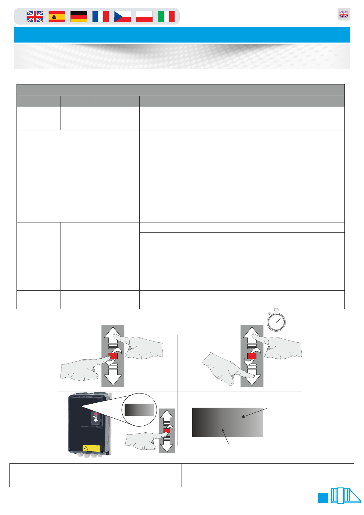
Reminder of how to enter/exit and navigate menus:
1. 2.
STOP
4.3.
P.999
1. Enter menu by pressing “stop” and “up” together
3. Press “stop” key to view parameter currently shown on
display
STOP
2. Use “up” and “down” arrows to scroll through parameters
4. LED dot flashes when changes are un-saved - press and
hold stop to save changes you have made
.0.99
LED Dot
Normal State = Static
Changed State = Flashing
STOP
60
5
55
10
50
10 mins
15
45
40
20
35
25
30
LED Letters
or numbers
19
Page 20
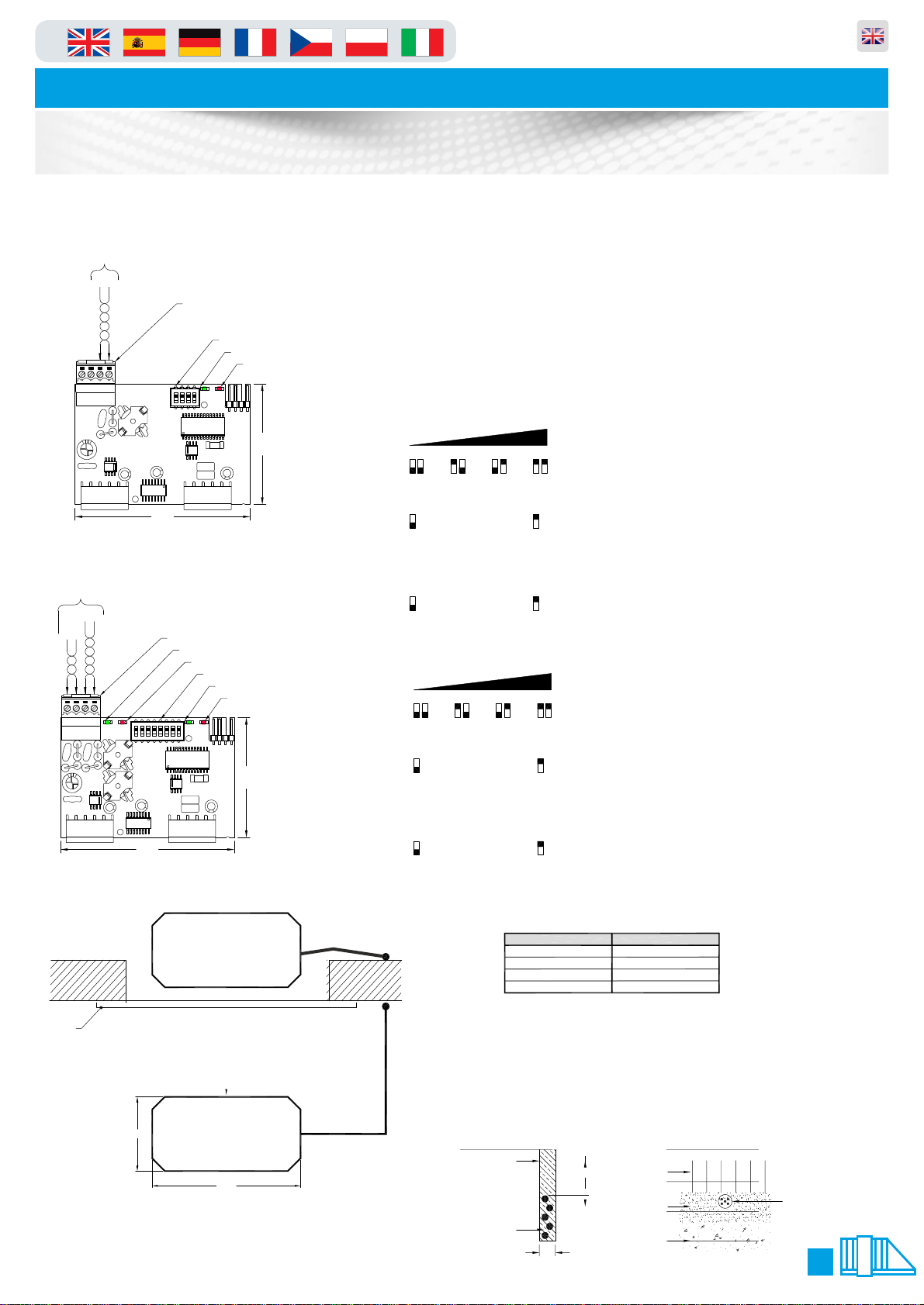
in
Automatic Sliding Gates
Loop Detector Settings
1 CHANNEL LOOP DETECTOR LAYOUT
Stock Code: TST-SUVEK1
TWISTED PAIR
CONNECTION
LOOP
#1
Terminal Connector
Function Dip-Switches
12
1 234
LOOP 1
ON
SUVEK1-A13
72.50
2 CHANNEL LOOP DETECTOR LAYOUT
Stock Code: TST-SUVEK2
TWISTED PAIR
CONNECTIONS
LOOP
#1
LOOP
#2
Terminal Connector
21
876543
'Power' Green L.E.D.
'Fault/Detect' Red L.E.D.
Function Dip-Switches
'Power' Green L.E.D.
12
LOOP 1LOOP 2
ON
SUVEK2-A13
'Power' Green L.E.D.
'Fault/Detect' Red L.E.D.
50.00
'Fault/Detect' Red L.E.D.
50.00
OPERATING INSTRUCTIONS
1. Turn OFF power to the control panel.
2. Plug the loop detector module into the pins provided on the motherboard of the control panel.
3.
4. Turn ON power to the control panel.
5.
6. If a loop is faulty/not connected properly the red `Fault/Detect` L.E.D. will illuminate constantly.
7. If
Parking and access control equipment manufactured in the UK
Adjust the function Dip-Switches on the loop detector card as required.
Please refer to Dip-Switch Function Settings.
The green `Power` L.E.D. will flash continuously until the loop is tuned.
Once tuned, the green `Power` L.E.D. will illuminate constantly.
a loop is covered the red `Fault/Detect` L.E.D. and the green `Power`
L.E.D. will illuminate together.
DIP-SWITCH FUNCTION SETTINGS
Loop 1:
DIP-Switches 1 & 2:- Sensitivity (4 Steps)
Detector is Tuning
Green Fast Flashing:-
Detector is Ready
Green ON Constantly:-
Loop has Detected
Green & Red ON Constantly:-
Loop is Defective
MIN. MAX.
ON ON ON ON
1
2 21 1 2 2
1
DIP-Switch 3:- Holding Time (5 mins - Infinity)
3
= 5mins
= INFINITE
3
Note:- Loop will recalibrate after 5 minutes constant detection
DIP-Switch 4:- Frequency (High/Low)
4
= HIGH
4
= LOW
Loop 2:
DIP-Switches 5 & 6:- Sensitivity (4 Steps)
MIN.
ON
ON ON
5
66 5 5 6 6
MAX.
ON
5
DIP-Switch 7:- Holding Time (5 mins - Infinity)
7
= 5mins
= INFINITE
7
Note:- Loop will recalibrate after 5 minutes constant detection
L.E.D. INDICATIONS
Red ON Constantly:-
DIP-Switch 8:- Frequency (High/Low)
72.50
TYPICAL EXAMPLE OF LOOP INSTALLATION
DOOR
1.0m
SAFETY
LOOP
AUTO
LOOP
2.0m
FEEDER CABLE IN TO
20mm PLASTIC CONDUIT
No. OF TURNS IN LOOP:
TWO or MORE LOOPS:
TO ENABLE LOOP WHEN PLUGGED
INTO PANEL P.802=0302
= HIGH
8
LOOP CABLE:
LOOP SIZE:
LOOP SLOT:
FEEDER CABLE:
LOOP PLACEMENT:
= LOW
8
INSTALLING A LOOP
Rubberised insulated wire of 0.75-1.50 sq.mm
(awg 20 - awg 16), preferably multi-stranded.
Note:- High bed vehicles require larger loops.
LOOP CIRCUMFERENCE
2 - 4m
4 - 7m
7 - 12m
12 - 25m
Recommended depth to top of loop cable 25-50mm. (Maximum depth 65mm)
Loop slot MUST be sealed after cable has been installed and tested.
Use a flexible, weather proof sealant (i.e. Hot bitumen, Rubberised bitumen sealant).
CAUTION! Never use cement / concrete, etc...
The feeder cable MUST be twisted a minimum 10 times
per meter & can be up to 250m long.
The loop must be placed at least 5m away from high tension cables and at least 1m away
from low tension cables. If the loop is placed in an area with reinforcing iron (typically a
concrete floor), the loop must be placed at least 50mm above the reinforcement.
If the detector is used for detecting high vehicles (lorries etc.) use only one loop for each
detector, otherwise it is possible to connect two loops to a single detector. Series coupling
the loops will give the largest sensitivity, parallel coupling gives the fastest reaction.
CONCRETE / TARMAC
SEALANT
25-50mm
LOOP
CABLE
5-10mm
NUMBER OF TURNS
6
5
4
3
BLOCK PAVING
BLOCK
SAND
BASE
PLASTIC CONDUIT WITH
LOOP CABLE INSIDE
20
Page 21
in
Automatic Sliding Gates
Loop Detector Settings
Parking and access control equipment manufactured in the UK
21
Page 22
in
Automatic Sliding Gates
Troubleshooting Guide
Parking and access control equipment manufactured in the UK
ELECTRICAL ERRORS
Blank screen on Panel but power to other devices
in the control panel
gate does not run (stays open)
Mains on but no power Isolator fuse Check and meter fuse in isolator
CAUSE CORRECTION
Door switch circuit not making Press door switch in and check Panel screen
Panel has developed an electrical fault or had a
power spike or blown on board fuses
Check panel is showing no F Codes or E codes Power down then back up press and hold “stop”
Loop detector is faulting or sensing presence Clear obstacle or reset the detector
Check panel settings have not been altered Set P.990=1 then P.991=0101
gate staying up in raise position Access control giving a constant pulse shorten
Photo cell batteries (if fitted)
Photo cells dirty (if fitted)
Change fuses or panel MAKE SURE that the
panel is run through a MCB 14 amp breaker
key to reset
this
Check that the fitted batteries still have power to
them. They should only be replaced with special
3.6V Lithium-ion batteries made for purpose. These
can be provided by your supplier
Clean photo cells make sure they are debris free
gate not going up Access control may be faulty Remove and check gate function via the Panel
gate Staying up Car has driven off before clearing the loop panel
“e.211” displaying on screen
gate staying open and not closing
is configured without “no passage” timer.
gate door is open Close door or check switch for faults
If photo-cells fitted then batteries may have
expired
Faulty loop detector Check & set or replace faulty unit
gate does not have loops fitted or these have
been removed
Key switch left in open position Put the switch back into the “Auto” position
Permanent supply/signal to the raise terminals Check wiring to terminal blocks remove any
gate programmed for safety only or gate is on a
timer
Complete cycle by going through the ground loop
Check and if needed replace batteries
Call the technical department for assistance the
program/wiring needs to change
Contact your supplier for a program modifacation
buttons
access control try again
chip
22
Page 23
in
Automatic Sliding Gates
Troubleshooting Guide
Parking and access control equipment manufactured in the UK
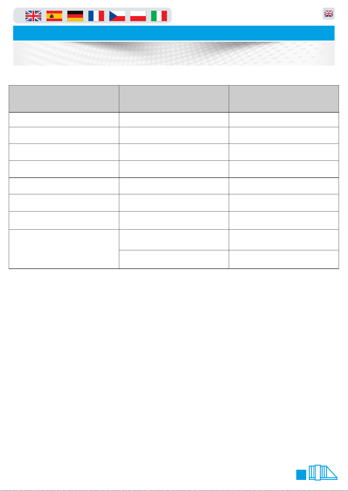
MECHANICAL ERRORS
Gate not Moving Motor brake locked on Check brake is releasing
Gate creaking when moving Gate alignment Check and align gate correctly
Gate motor not running Loss of voltage Check motor supply test 3 phases
Gate not moving or closing Drive shaft connections Re-connect any drive shaft connections
Gate not moving or moving half way Gearbox or gate track damaged Gears/Track stripped due to overlading replace
Gate crashes into catch post Cantilever arm not adjusted correctly Adjust and check alignment
Gate not running at all Door has been left open or switch not making Close the door and check display is not reading
Gate open and will not close Key switch is left in open position Turn key switch to auto if fitted
CAUSE CORRECTION
e.211
Loop fault or loop detecting Check if green light is on detector if so remove
object that it is detecting or replace loop
Notes Area
23
Page 24

in
Parking and access control equipment manufactured in the UK
Automatic Sliding Gates
Potential System Hazard Areas
Please note these are things that you should look out for with the equipment that has been installed on
your/your customers site. This is in no way a health and safety guide just a few key areas for you to be
aware of and possibly make future changes to.
Plan view (from above)
Sketch system layout, detailing and numbering potential hazard areas for the client.
Potential Hazard Areas - see diagram:
1.................................................................................................................................................................
2.................................................................................................................................................................
3.................................................................................................................................................................
4.................................................................................................................................................................
5.................................................................................................................................................................
Additional Comments / Descriptions concerning safety on this site
................................................................................................................................................................
................................................................................................................................................................
................................................................................................................................................................
................................................................................................................................................................
................................................................................................................................................................
..................................................................................Signed:....................................................................
24
Page 25
in
Automatic Sliding Gates
Handing Form
Section 1. What type of Gate do you require?
Parking and access control equipment manufactured in the UK
PF9000M Manual Sliding Gate
Section 2a. Additional Information
Additional Information for our records
What is the span of the clear
opening?
PF Quote Refrence
Your Order Number
Customer Contact No.
Height of Gate required
Spikes Required? (yes or no)
Type of Infill Required:
Todays Date:
Required Delivery Date:
Section 3. Gate Handing Choice
PF9000A Automatic Sliding Gate
Gate length = mm
Colour code required:
(please specify RAL or BS Colour
Below)
If more than one Gate
how are they operating?
Master/Slave
Independant
I require a LEFT handed gate shown above I require a RIGHT handed gate shown above
Section 4. Accessories Required
UPS Battery back-up used for panel protection and gate can open/close automatically after power loss. HIGHLY RECOMMENDED!
Section 5.a Delivery or Install Address
PF to install equipment
Section 5.b Additional Information (Use a separate sheet if necessary)
PF to supply only
25
Page 26
in
Automatic Sliding Gates
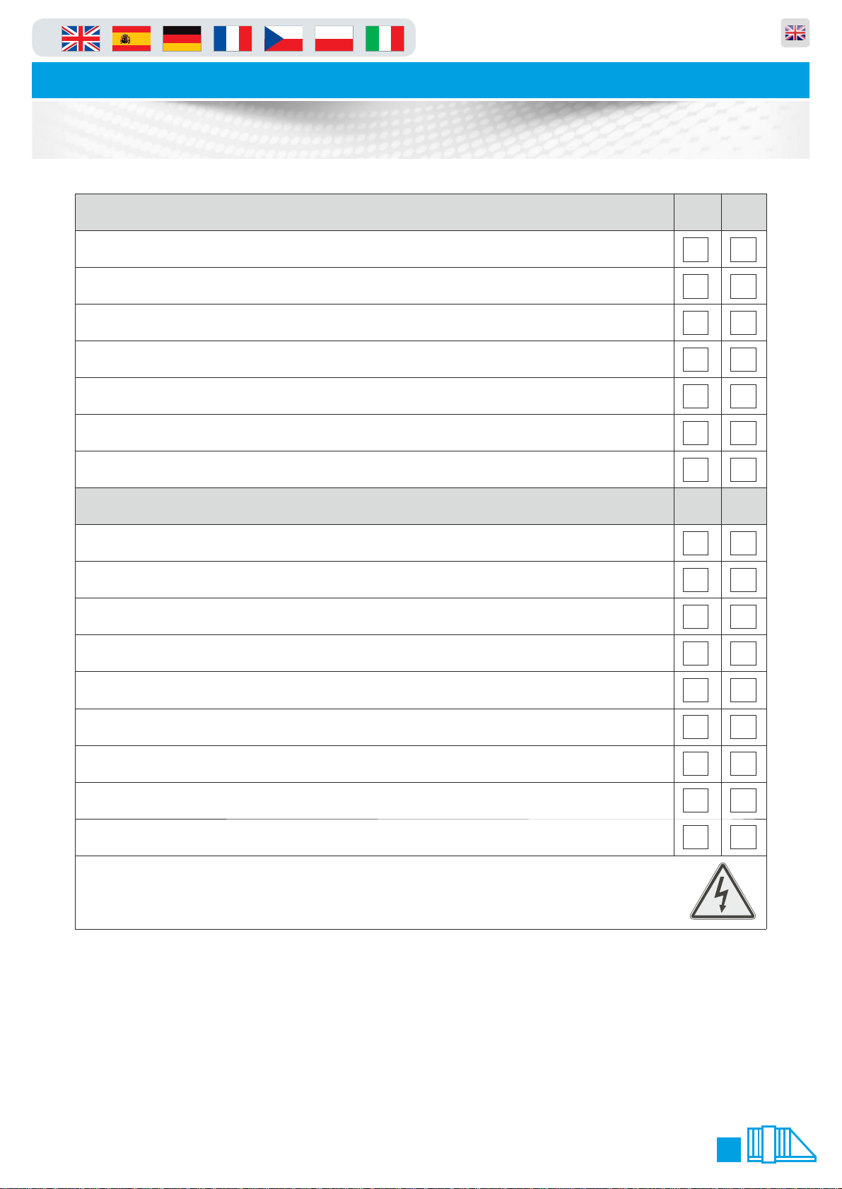
Installation & Commissioning Check List
System Operation - The user FULLY understands YES NO
How to operate the system with all control devices
How to isolate the power to the automation system
How to manually release the system in event of power failure
The safety rules and issues associated with your system
Safety devices on the system have been verified and checked
Safety devices and features suit the site/application for which it was designed
Parking and access control equipment manufactured in the UK
How to open the door on the equipment
Check the following items YES NO
Door keys have been handed over
Key switch keys have been handed over
All equipment and site has been left in a clean and safe state
Any warning signage has been fitted by Engineer/Client to make people aware
Any times and special programming instructions undertaken
Product works the way site need it to this includes “no passage time out” etc
System has had the completed conformity certificate
All items on the delivery note have been handed over to client/site -
this should be signed for on the separate sheet which is titled “Delivery Note” (green/ or yellow paper) if parts missing call supplier
The engineer has expressed the importance of regularly maintaining the equipment
POWER ISOLATION - The power isolator for your automation system is located at:
.....................................................................................................................................................
The following denotes that the above has been completed to a satisfactory standard. The engineer has explained the system of
operation to you and any devices that you have had fitted. If this is agreed and has been displayed please sign in the indicated
fields below. All information will be passed on correctly to other system users. The users of the system will use this system
correctly and safely.
Engineers Name: ........................................................................ Engineers Signature: ...........................................
Clients Name: ............................................................................. Clients Signature: .................................................
26
Page 27
in
Parking and access control equipment manufactured in the UK
Automatic Sliding Gates
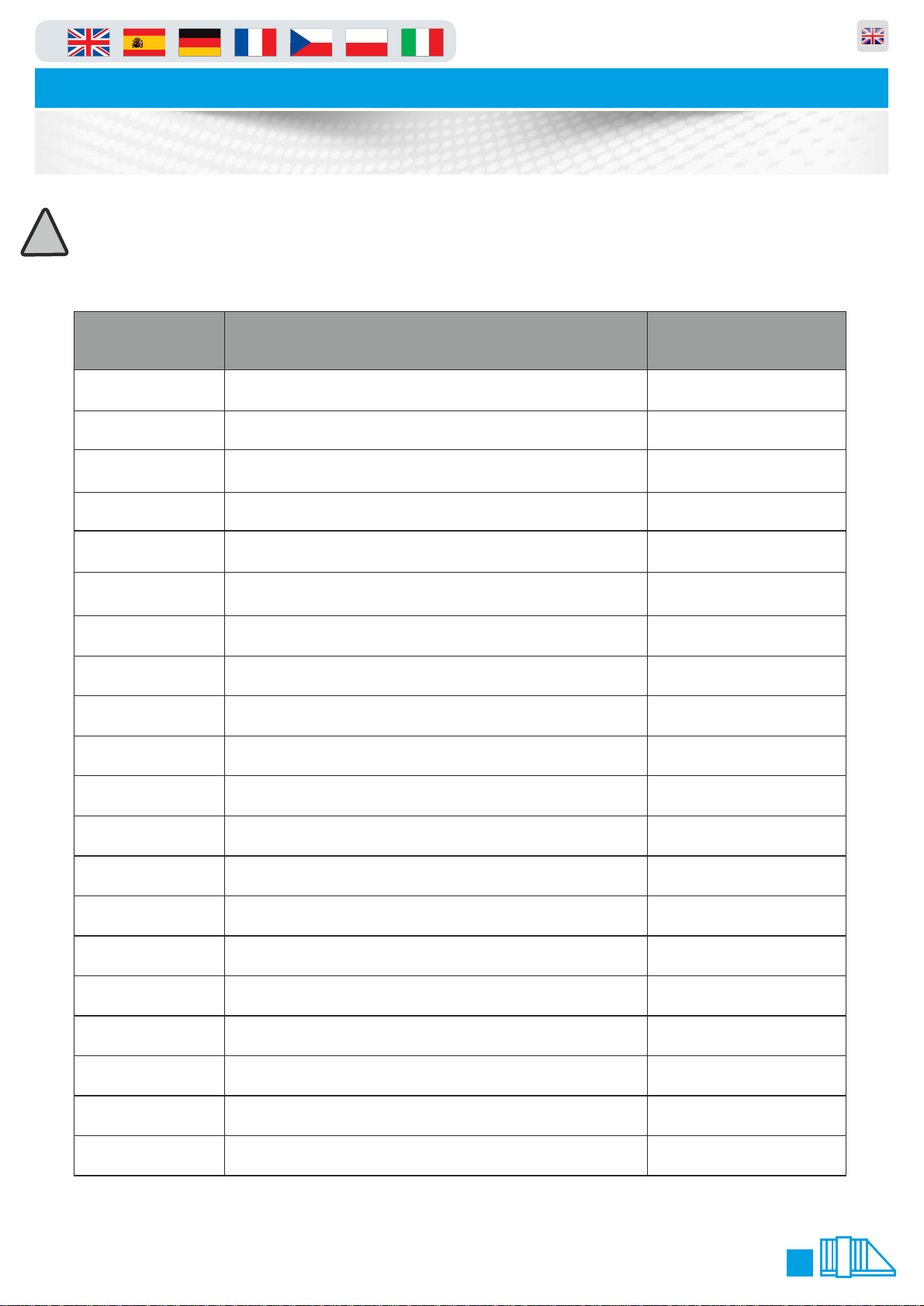
Service Log
This Manual must be completed in accordance with the guidelines below, at any point service/repair work is
carried out on the product. This is to achieve two things;
!
1. To keep a history of the product for yourself and your supplier/manufacturer.
2. To keep an accurate log of any historical or recent modifications, and/or problems, to help an engineer in
the event of any future work required on the product.
Date
/ /20
/ /20
/ /20
/ /20
/ /20
/ /20
/ /20
/ /20
/ /20
/ /20
Reason for visit/Action taken
Engineers Signature
/ /20
/ /20
/ /20
/ /20
/ /20
/ /20
/ /20
/ /20
/ /20
/ /20
27
Page 28
in
Parking and access control equipment manufactured in the UK
Automatic Sliding Gates
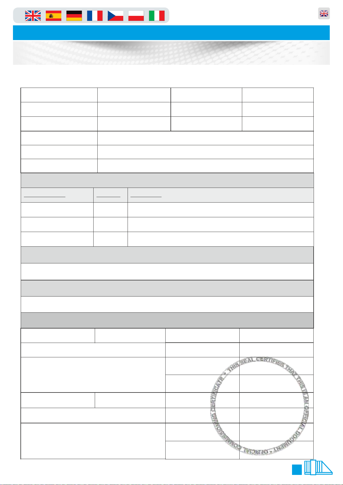
Commissioning Certificate
We certify that the system covered by this certificate has been commissioned satisfactorily.
Contract Reference
Contract Title
Installation Commenced / /20
Works Description
Part/Whole Certificate
Handover Date
Part 3.The system(s) designed and installed in accordance with the following documents:
Document Ref:
PF9000A/M
Part 4.The following test procedures refer:
Revision
5.0
Description
System guides and drawings as defined within O&M Manuals
Completion
Engineers Installing
Commissioning
Check Lists (pages 15 & 16) /Commissioning Certificate
Part 5. Existing Installation Items not covered under warranty/ This certificate:
Part 6. Certificate Signing off Section
Installers Name
On Behalf of
Address
Client Name
On Behalf of
Address
Signature
Date of Signing
Position
Parts Handed Over Qty:
Signature
Date of Signing
Position
Parts Handed over Qty:
28
Page 29

in
Automatic Sliding Gates
Declaration of Incorporation
We hereby certify that the machinery stipulated below complies with
all relevant provisions of the EC Machinery Directive and National
Laws and Regulations adopting this Directive.
Parking and access control equipment manufactured in the UK
Declaration
of
Incorporation
Manufacturer
& European
Agent:
Telephone:
Description:
Model Number:
Serial Number:
EU Directives &
Standards
Applied:
PF Ltd
Unit 1 Kingsbury Link Industrial Estate
Trinity Road
Tamworth
Staffs
B78 2EX
United Kingdom
01827 870 250
Automatic Cantilever Sliding Gate
PF9000A
The above product is in conformity with the essential Health and
Safety requirements of the Machinery Directive 2006/42/EC and the
following transposed harmonised standards, BS EN 292 Parts 1 &
2:1991, BS EN 60204 Part 1:1993, BS EN 294:1992, BS EN
249:1993, BS EN 418:1992, and BSEN13241-1 including other
standards BS EN 12445:2008, BS EN 12453:2008.
Responsible Person:
Damian Speer
PF Ltd
Name: Anthony Green
Signature:
Position: Managing Director
Date: 2nd November 2010
29
Page 30
in
Automatic Sliding Gates
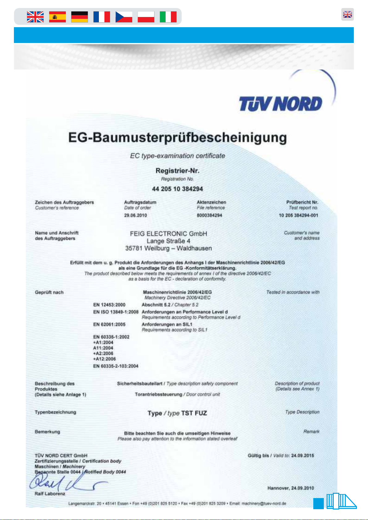
Electronics Certificate
Parking and access control equipment manufactured in the UK
30
Page 31

in
in
Automatic Sliding Gates
Automatic Sliding Gates
Notes
Parking and access control equipment manufactured in the UK
Parking and access control equipment manufactured in the UK
31
Page 32
in
Automatic Sliding Gate
Parking and access control equipment manufactured in the UK
EUROPEAN MARK CERTIFYING CONFORMITY
TO THE ESSENTIAL REQUIREMENTS OF THE
STANDARDS 2006/42/EC
Proudly Proudly MadeMade
Proudly Made
in the UK in the UK
Made using
recycled
paper
2003/108/CE Directive
GB
ENVIRONMENT - NOXIOUS MATERIALS
for waste electrical and
electronic Equipments
DISPOSE OF PROPERLY
The manufacturer reserves the right to make amendments to this manual without prior notice
and declines all responsibility for any errors, personal injury or damage to property.
 Loading...