

Page 1

PS-66 OPERATING INSTRUCTIONS
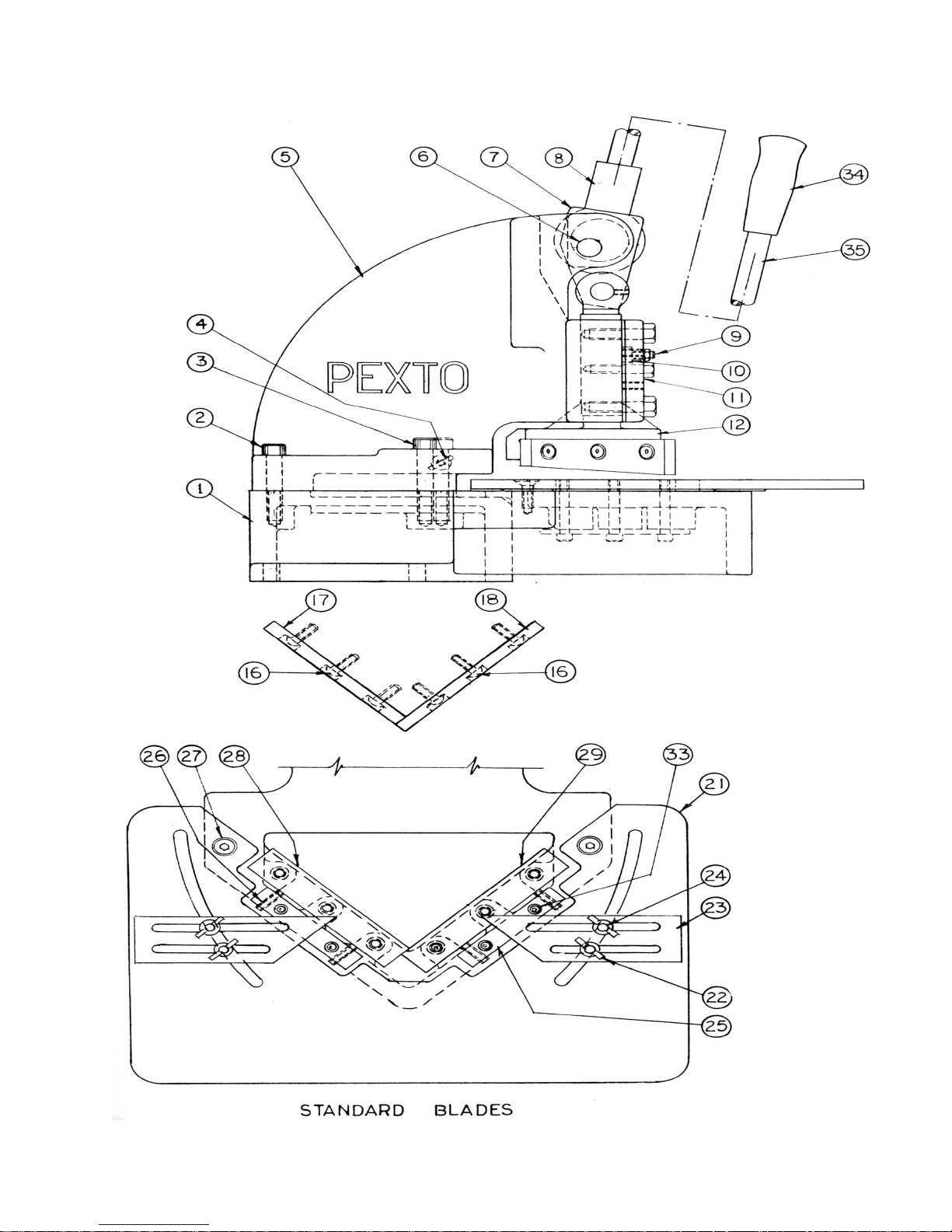
1. Mount and level Notcher with drop-out overhanging edge of bench and bolt or lag in place. Lubricate all
points with SAE 30 machine oil before operating.
2. Upper Standard Blades - 17 and 18 are set at factory for "pierce" cutting, starting at apex, or corner of inside
cut. To change to "splay" cutting, interchange blades 17 and 18 end for end so that cut starts at outside edge
of sheet. Align blades at point (elongated holes are provided in blades for this purpose) before tightening
blade bolts (16) securely.
3. Lower Standard Blades - 28 and 29 are each symmetrical and can be mounted to use all 4 cutting edges.
Blades are positioned by blade bolts (32) from underneath table.
4. Blade Adjustment:
A. Take off table (21) by removing two table screws (27)
B. Position the slide at bottom of stroke.
C. Loosen lower blade bolts (32) slightly.
D. Turn blade adjusting screws (26) mounted in adjusting plate (25) to bring blade to .002 normal clearance
between upper and lower blade. (Clearance should be greater for heavy stock - less for thin stock).
E. Tighten blade bolts (32) securely.
F. Remount table.
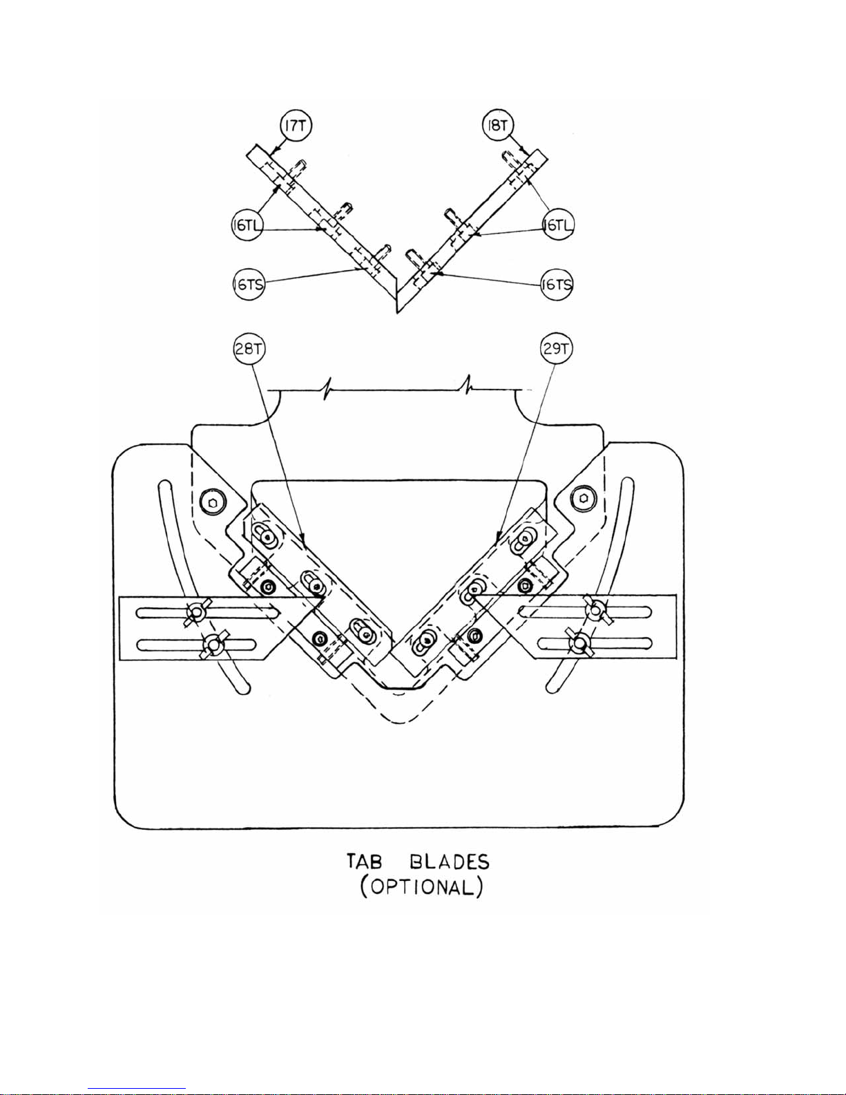
5. Tab Notching - To install tab blades:
a. Remove table (21) as in 4a and disassemble four standard blades.
b. Install top right hand (18T) and left hand (17T) tab blades using the 3/8" socket head cap screws furnished
with tab blade kit. (Use one 3/4 long screw (16TS) in front hole of each blade.) Tighten screws finger tight
until blades are properly positioned.
c. Top right hand blade should protrude past the edge of the left hand blade the desired depth of notch. Tighten
all screws securely.
d. Mount lower blades (28T & 29T), using blade plates (30T & 31T) furnished with kit, leaving screws finger
tight until proper setting is attained.
e. Position slide at bottom of stroke, taking care that lower blades are back, clear of the upper blades.
f. Set lower right hand blade so that front cutting corner is in line with front corner of the upper right hand blade
with the normal clearance of .002" between them. Tighten right hand blade screws securely.
g. Set lower left hand blade so that the notched front edge of the lower left hand blade just touches the front
corner of the lower right hand blade. Set for normal clearance of .002" between upper and lower blades and
at the beveled surface of the notch. Tighten lower left hand blade screws securely.
h. Check clearances at all points before operating.
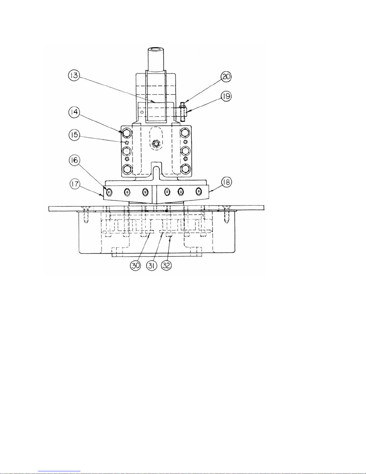
6. Depth of Cut can be limited by adjusting stop screw (20) and check nut.
7. Safety Brake is adjusted through screw (9) and check nut, to prevent dead-weight fall of handle and slide.
CAUTION: Check this adjustment frequently for safe operation.
8. Squaring or cut-off shearing stock of any length to 6 inches in width can be done by opening throat.
9. Throat - To open throat, back off frame bolt (3) and hold in "up" position with thumbscrew (4) Ito prevent its
being lost).
CAUTION: Open throat position used only for slitting, squaring and cut-o ff shearing.
Page 2

10. Slitting - Up to 6 inches wide strips can be slit from any width sheet. With upper blades mounted for "splay"
cutting, remove left hand upper blade (17) and open throat.
11. Frequent lubrication of slide ways and cam pivots will insure continued smooth operation.
12. Adjus tment of Slide - may become necessary to compensate for wear. Back off four slide adjusting screws
(15) and adjust slide cap screws (14) to "tight" fit. Then reset slide adjusting screw (15) to obtain sliding fit.
Oil ways.
13. Gage Setting - can be accomplished by using combination square. Table edges machined at 45º to cutting
edges.
14. Check clearances between upper and lower blades occasionally to see that normal .002 clearance is
maintained!
INDEX NAME PART NO.
1 BASE D6021
2 SHORT FRAME BOLT
3 LONG FRAME BOLT
4 THUMB SCREW
5 FRAME D 6020
6 CAM PIVOT A61219
7 LINK A60223
8 CAM A60218
9 FRICTION SHOE ADJ. SCREW
10 FRICTION SHOE A52149
11 SLIDE CAP B60141
12 SLIDE C6122
13 CAM ROLLER A60221
14 SLIDE CAP BOLTS
15 SLIDE ADJ. SCPEW
16 UPPER BLADE BOLTS
17 TOP L H BLADE A6226
18 TOP RH BLADE A6225
19 SLIDE PIVOT A60222
20 SLIDE STOP SCREW
21 TABLE D6022
22 THUMB NUT
23 GAUGE A62155
24 TEE BOLT 12438
25 ADJ.PLATE A60228
26 BLADE ADJ. SCREW
27 TABLE SCREW
28 LOWER L.H. BLADE A60227
29 LOWER R.H. BLADE A60226
30 L.H. BLADE PLATE A6217
31 R.H. BLABE PLATE A6219
32 LOWER BLADE SCR.
33 ADJ. PLATE SCREW
34 HANDLE GRIP
35 HANDLE A60220
TAB BLADF- KIT
16T TOP R.H. BLADE A62294
17T TOP L.H. BLADE A62295
29T LOWER R.H.BLADE A62296
26T LOWER L.H.BLADE A62297
31T R. H. BLADE PLATE A62298
30T L. H. BLADE PLATE A62299
16TS 3/8 x 3/4 SOC. HD. CAP SCR.
16TL 3/8 x 1 SOC.HD.CAP SCR.
5/16 KEY WRENCH
Page 3
Page 4
Page 5
 Loading...