

Page 1
V1.1/1012
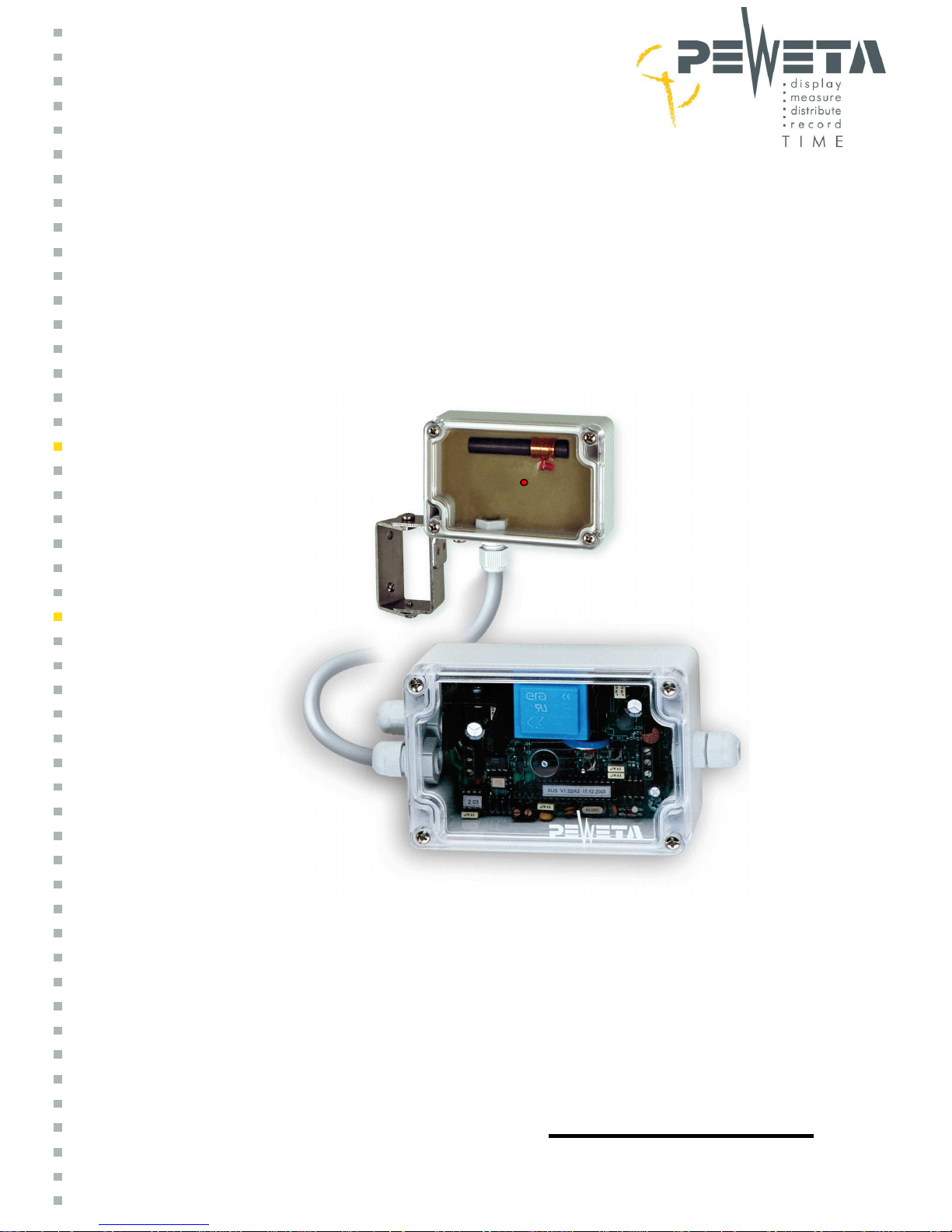
DCF77 Radio Control Unit
output: alternating polarity minute pulse 24 V line voltage
Item No. 10.950.100, 10.950.101
installation manual
Page 2

- 2 -
For your better understanding please read this instruction manual once before installation!
1.0 application and function
By means of a DCF77 aerial this
control unit receives the exact time including the trigger signal for
the automatic change-over between summer and winter time. In case of impaired reception due to
local conditions pulse transmission to the slave clocks connected will be kept up. After a power
outage the slave clocks connected will automatically be adjusted to match the correct time. After
installation the control unit operates completely autonomous and maintenance-free.
This control unit, governed by DCF77, is capable of controlling up to four indoor/outdoor slave
clock movements (6mA at 24 V each). Specifically suited to operate outdoor clock movements
(e.g. with advertising) and all other single, double, or 4-faced slave clocks.
2.0 pay attention before and during installation
All electrical installation works must be carried out by skilled persons only.
Watch and stick to national rules, standards and norms.
All cables and wires have to be disconnected before start of installation works.
3.0 security and disconnection
All-pole disconnection of 230 VAC mains operated fixed devices has to be secured by all-pole
disconnection switch(es) at site!
4.0 put into operation
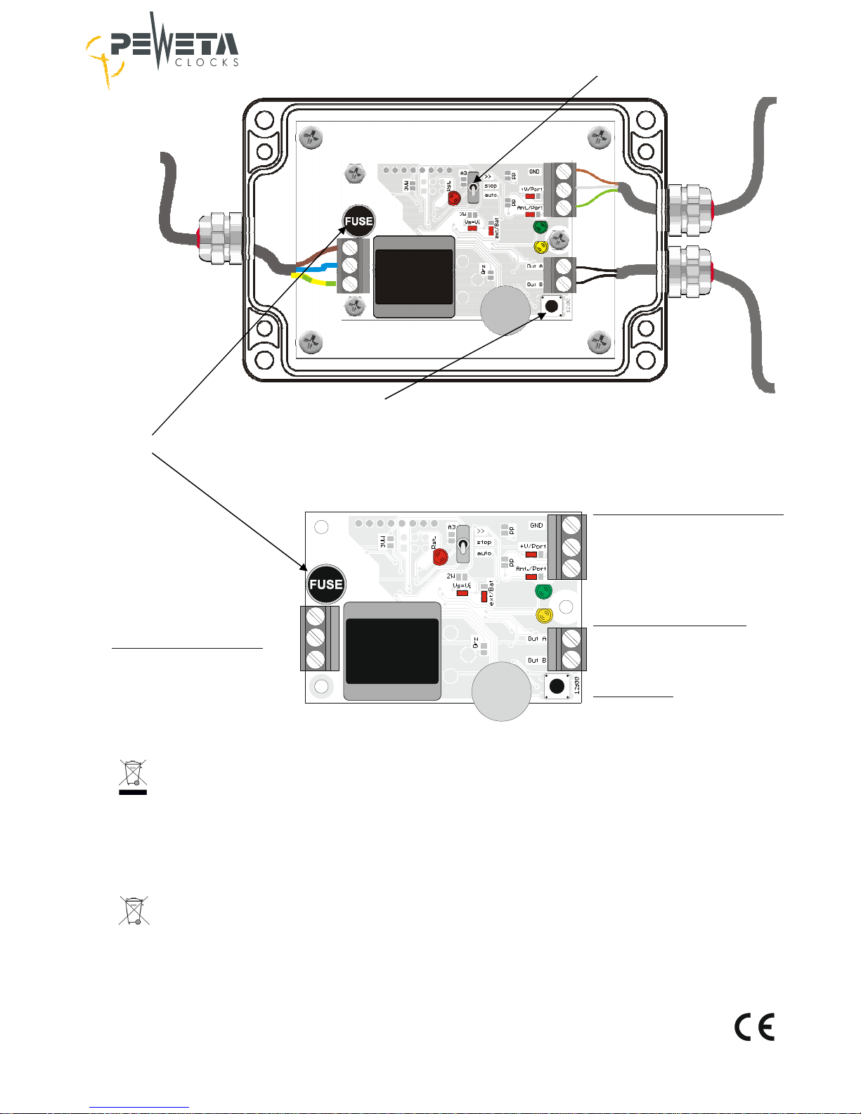
4.1 Put small metal-silver colored switch in position „stop“, see picture on page 4.
4.2 Connect control unit to mains power 220..230 VAC/50..60 Hz (fixed connection only), sticking
to national rules and instructions. The red and the green LED inside the control unit will blink
in seconds rhythm.
4.3 Adjust hour and minute hands of your slave clock(s) exactly to 12:00 position by turning the
small adjusting wheel at the slave clock movement.
4.4 Make sure that slave clock movement is adjusted to 24 V line voltage, see instruction manual
of slave clock movement.
4.5 Press “12:00 key” once, see picture on page 4. The red LED will blink 3 x for confirmation.
4.6 Now 1 minute pulse will be emitted. The minute hand(s) of your slave clock(s) should
now make 1 minute step, the clock hands show 12:01.
Note: If the minute hand(s) did not make 1 minute step change polarity at the corresponding
slave clock movements. How to do it see installation manual of the corresponding
slave clock movements. Press “12:00 key” again.
4.7 Put small metal-silver colored switch in position „auto“, see picture on page 4.
4.8 From now on 1 alternating polarity minute pulse 24 V will be emitted, the minute hand(s)
will make 1 minute step each 60 seconds.
4.9 The green and the red LEDs will blink in seconds rhythm.
4.10 Now mount DCF77 receiving aerial (= antenna) on best position to receive best quality of
DCF77 signals. Best reception conditions are achieved when red LED in antenna and green
LED in control unit will blink in steady, regular seconds rhythm.
4.11 Under normal conditions hour and minute hand(s) will now start moving in fast steps to
adjust clock(s) to local current time. Compare with a separate reference clock.
4.12 Now fix/mount DCF77 receiving aerial on final position and do not change position anymore.
Page 3

- 3 -
5.0 technical information
5.1 Operates up to max. 4 slave clock movements (6 mA at 24 V) in in- and outdoor clocks,
alternating polarity minute pulse 24 V line voltage, total output power approx. 24..30 mA at
24 V line voltage.
5.2 Operating power is mains 220..230 VAC/50..60Hz, power consumption max. 2 VA.
5.3 Electronic buffer memory and update circuitry, fuse: 250 V 80 mA, slow-blow.
5.4 Fully automatic read-in of current time upon installation or after power outage, automatic
change-over between summer and wintertime.
5.5 12:00 key for synchronization of connected slave clock(s).
5.6 Switch
„auto“ : regular operation with fully automatic time set-up when mains power returns
after mains power failure.
„stop“ : alternating polarity minute pulses will not be emitted.
„>>“ : fast forward trigger of clock hands.
5.7 Accuracy without DCF77 synchronization: +/- 0.5 seconds/24 hrs.
5.8 Protection grades:
Control unit : IP 54/EN 60529
DCF77 antenna: IP 68/EN 60529
5.9 Temperature range for control unit and DCF77 antenna: - 10°C…+ 40°C.
5.10 LEDs in control unit:
- green: reception quality of DCF77 radio control signal.
- red: blinks once each second: no DCF77 reception within the past 24 hours or no
DCF77 reception after mains power failure.
- red: blinks twice each second: short circuit at slave clock movement(s) and/or more
than 4 pcs slave clock movements connected.
- red: blinks 3 x once : confirmation of having successfully taken over the
12:00 position.
- yellow: blinks when an alternating polarity minute pulse has been emitted.
5.11 LEDs in DCF77 receiving aerial:
- red: shows reception quality of DCF77 radio control signal
- regular, in second’s rhythm = good quality
- irregular, flickers = poor quality or no reception.
5.12 External DCF77 receiving aerial: plastic case, protection grade IP 68/EN 60529, for in and outdoors mounting, incl. stainless steel mounting bracket. 5 m connecting wire
(LIYCY 4 x 0.25 sqmm) included, extendable up to max. 100 m “in situ”.
Page 4
- 4 -
DCF77 receiving aerial
brown (GND)
white (+3V)
green (signal)
slave clock(s) 24V
A
B
L
N
PE
230 VAC/50..60 Hz
12:00 key
■ Entsorgung von Altgeräten
Im Interesse unserer Umwelt und um die
verwendeten Rohstoffe möglichst vollständig zu recyceln,
ist der Endnutzer aufgefordert, gebrauchte und defekte Geräte
zu den öffentlichen Sammelstellen für Elektro-und Elektronikschrott
zu bringen. Das Symbol der durchgestrichenen Mülltonne mit Balken
bedeutet, dass dieses Produkt an einer Sammelstelle für Elektro- und
Elektronikschrott abgegeben werden muss, um es durch Recycling einer
bestmöglichen Rohstoffwiederverwertung zuzuführen. Altgeräte dürfen nicht
über den Hausmüll entsorgt werden.
■ Entsorgung von Altbatterien/Akkus
Batterien und Akkus können nach Gebrauch
an der Verkaufsstelle oder an den Sammelstellen
unentgeltlich zurückgegeben werden. Endnutzer sind
gesetzlich zur Rückgabe von Altbatterien und Akkus
verpflichtet. Das Symbol der durchgestrichenen Mülltonne bedeutet,
dass verbrauchte Batterien/Akkus an einer Sammelstelle für Altbatterien
abgegeben werden müssen, um sie durch Recycling einer bestmöglichen
Rohstoffwiederverwertung zuzuführen. Altbatterien/Akkus
dürfen nicht über den Hausmüll entsorgt werden
Symbole auf Batterien/Akkus bedeuten:
Cd=Cadmium, Hg=Quecksilber, Pb=Blei.
fuse: 250 V 80 mA slow blow
Control unit
12:00 key
switch
For any queries, additional information and
further questions please contact:
mains power
DCF77
slave clock
PEWETA KG (GmbH + Co.)
Holsteinischer Kamp 64-66
22081 Hamburg, Germany
[email protected]
www.peweta.com
Tel ++49 – 40 – 20 98 97 0
Fax ++49 – 40 – 20 98 97 96
 Loading...