

Page 1
Operating Guide
Guide d’emploi
Guia para el uso
Please read this entire guide before installing.
Veuillez lire tout ce manuel avant de commencer.
Por favor, lea completamente esta guía antes de comenzar.
Model Numbers: PPA11-10711 Small, PPA11-10709 Large
Numéros de modèles : Petit PPA11-10711, Grand PPA11-10709
Números de modelo: PPA11-10711 Pequeño, PPA11-10709 Grande
Page 2

Important Safety Information
Explanation of Attention Words and Symbols used in this guide
This is the safety alert symbol. It is used to alert you to potential personal
injury hazards. Obey all safety messages that follow this symbol to avoid
possible injury or death.
WARNING
CAUTION
NOTICE
WARNING
WARNING indicates a hazardous situation which, if not avoided, could
result in death or serious injury.
CAUTION, used with the safety alert symbol, indicates a
hazardous situation which, if not avoided, could result in minor or
moderate injury.
NOTICE is used to address safe use practices not related to
personal injury.
• When children are present in the home, it is important to consider the
pet door during child proofi ng activities. The pet door may be misused
by a child resulting in the child accessing potential hazards that may
be on the other side of the pet door. Purchasers/Homeowners with
swimming pools should ensure that the pet door is monitored at all
times and that the swimming pool has adequate barriers to entry.
If a new hazard is created inside or outside of your home, which
may be accessed through the pet door, Radio Systems® Corporation
recommends that you properly guard access to the hazard or remove
the pet door. The closing panel or lock, if applicable, is provided
for aesthetic and energy effi ciency purposes and is not intended
as a security device. Radio Systems® Corporation will not be liable
for unintended use and the purchaser of this product accepts full
responsibility for oversight of the opening it creates.
• Power Tools. Risk of severe injury; follow all safety instructions for
your power tools. Be sure to always wear your safety goggles.
CAUTION
NOTICE
2 1-800-732-2677
The user, prior to installation, must become familiar with all building
codes that may affect the installation of the pet door and determine,
along with a licensed contractor, its suitability in a given installation.
This pet door is not a fi re door. It is important for the owner and
contractor to consider any risks that may be present inside or outside of
the pet door, and any risks that may be created by subsequent changes
to your property and how they may relate to the existence and use,
including misuse of the pet door.
• Keep these instructions with important papers; be sure to
transfer these instructions to the new owner of the property.
• Unauthorized changes or modifi cations may void the user’s
authority to operate this equipment, and void the warranty.
Page 3

Thank you for choosing the PetSafe® brand. You and your pet deserve a companionship that
includes memorable moments and a shared understanding together. Our products and training
tools promote a lifestyle of protection, teaching, and love—essentials that infl uence memories
for a lifetime. If you have any questions about our products or training your pet, please visit our
website at www.petsafe.net or contact our Customer Care Center.
PRODUCT WARRANTY
To get the most protection out of your warranty, please register your product within 30 days at
www.petsafe.net. By registering and keeping your receipt, you will enjoy the product’s full
warranty and should you ever need to call the Customer Care Center, we will be able to help you
faster. Most importantly, PetSafe
Complete warranty information is available online at www.petsafe.net.
®
will never give or sell your valuable information to anyone.
________________________________________________________________________________
Table of Contents
Components .....................................................................................................................4
Tools Needed .................................................................................................................... 4
How the SmartDoor™ Works ................................................................................................ 4
Install the SmartDoor™ Through a Wall with the SmartDoor™ Conversion Kit ............................... 4
Key Defi nitions .................................................................................................................. 4
PREPARE
A. Place Batteries in SmartDoor™ ...................................................................................... 5
B. Place Battery in SmartKey™ .......................................................................................... 6
C. Check Operational Mode Before Installation ................................................................... 6
D. Check SmartDoor™ Location Before Installation .............................................................. 7
INSTALL
Installing your SmartDoor™ .............................................................................................. 7
SET
A. Setting SmartDoor
B. Understanding Sensitivity and the Active Area .............................................................. 10
C. Programming a New SmartKey™ ................................................................................. 11
D. Attaching SmartKey™ to Collar .................................................................................... 11
OPERATE
Operating Your SmartDoor™ ........................................................................................... 11
Troubleshooting Chart ...................................................................................................... 11
Revert SmartKey™ to Factory Default Settings ...................................................................... 12
Clear SmartKey™ Memory ................................................................................................. 12
Replacement Parts and Accessories .................................................................................... 12
Customer Care - International ........................................................................................... 12
Terms of Use and Limitation of Liability ............................................................................... 13
Perchlorate Battery .......................................................................................................... 13
Important Recycling Advice ............................................................................................... 13
Battery Disposal .............................................................................................................. 13
Compliance ..................................................................................................................... 13
Français ........................................................................................................................ 15
Español ......................................................................................................................... 29
™
’s Sensitivity Level ........................................................................ 10
www.petsafe.net 3
Page 4
Components
Operating Guide
Cutting Template
Located inside the battery
compartment is the SmartKey
battery, mounting screws and key ring.
Interior Frame
with Flap
Exterior Frame
™
, RFA-67
™
SmartKey
Mounting Screws
(4 pcs. small door)
(8 pcs. large door)
Key Ring
Battery
(PetSafe
RFA-67)
®
Tools Needed
• Jigsaw or Keyhole Saw
• Electric Drill
• ⅜” (10 mm) Drill Bit
• Phillips Screwdriver
• 4 D-Cell (LR20)
Batteries (required)
• Level
• Tape
• Pencil
• String
____________________________________________________________________________________________________________________________________________
How the SmartDoor™ Works
Using radio-frequency technology, the SmartDoor™ reads a SmartKey™’s unique signal and triggers
a battery power-driven fl ap to unlock so your pets can come and go as they please. When the
SmartDoor™ no longer senses your pets’ SmartKey™, the fl ap automatically locks back into place.
The SmartDoor™ can detect up to fi ve programmed SmartKeys™ and also operates in two other
modes: fully locked mode and unlocked mode.
Install the SmartDoor™ Through a Wall with the
SmartDoor
SmartDoor™ Conversion Kits are available for wall installation applications. The wall extension
conversion kit frames out exposed areas, giving your door installation a clean, smooth, fi nished
look. For brick, concrete or block wall construction an additional extension is available for the
large conversion kit. Note: The SmartDoor™ Conversion Kit Small is designed to be recessed into
the brick and does not require additional tunnel extensions. You may purchase a SmartDoor™
Conversion Kit or large extensions through selected online websites, www.petsafe.net or by calling
our Customer Care Center. See “Replacement Parts” on page 12.
™
Conversion Kit
Key Defi nitions
Radio-Frequency Technology – The use of a radio-frequency signal that can be transmitted
without wires.
SmartKey™ – A SmartKey™ is a battery-operated transmitter that sends a unique code to
the SmartDoor™.
4 1-800-732-2677
Page 5

SmartDoor™ – The SmartDoor™ is an intelligent receiver using an internal antenna to pick up a
unique SmartKey™ code for selective pet entry and exit.
SmartDoor™ Flap – The SmartDoor™ fl ap is a weather resistant, plastic fl ap with UV
sun protection.
Antenna - The antenna is located inside the SmartDoor™ and receives radio signals from the
SmartKey™. The SmartKey™ must be located within a certain proximity of the antenna in order for
the unique code to be read.
Radio-frequency Interference – Radio-frequency interference is due to radio-frequency signals
from other household appliances or common electronic products that negatively affect the ability
of the SmartDoor
can come from a variety of sources. Interference can be minimal, constant or ever changing based
on usage and closeness of other electronic household items during SmartDoor
™
to receive a signal from a SmartKey™. Radio-frequency interference or “noise”
™
’s operation. It is
recommended that household appliances and common electronic products be placed at least two
feet (60 cm) away from the SmartDoor™’s location.
Sensitivity Knob – Conveniently placed on the interior frame of the SmartDoor™ is the sensitivity
knob. You can easily adjust the SmartDoor™’s sensitivity, taking into account common interferences
and environmental factors to optimize SmartDoor™ operation.
Sensitivity Level – The level of sensitivity can be adjusted by turning the sensitivity knob
from minimum to maximum, depending on radio-frequency interference and the SmartDoor™’s
application and/or location. Pre-set from the factory, the sensitivity level should not be adjusted
until after installation. For example, the sensitivity level may need to be increased if the
SmartDoor™ is installed in a metal door. Reference page 10 for more information on how to
adjust sensitivity.
MODE-RESET Button – Easily select an Operational Mode on your SmartDoor™ by holding the
MODE-RESET button to cycle through selections of operation: LOCKED, UNLOCKED or AUTOMATIC.
LEARN Button – The LEARN button programs a SmartKey™’s unique code to be read by the
SmartDoor™. (One) SmartKey™ comes programmed and ready to use. You may program up to fi ve
SmartKeys™ (each sold separately) to one SmartDoor™.
Operational Modes
LOCKED Mode – The SmartDoor™ fl ap is locked and does not allow entry or exit for any pet.
™
UNLOCKED Mode – The SmartDoor
AUTOMATIC Mode – The SmartDoor
fl ap is unlocked and allows entry and exit for all pets.
™
fl ap is electronically locked and allows entry and exit for
the pet wearing a programmed SmartKey™.
Battery Compartment – The battery compartment is located on the Interior Frame and requires
(four) D-cell (LR20) batteries. Installation mounting screws, key ring, SmartKey™ and the (one)
RFA-67 battery are all located inside the battery box during shipping for your convenience.
RFA-67 Battery – The RFA-67 battery powers the SmartKey™ and is replaceable. Additional
RFA-67 batteries are available at retailers, or by calling PetSafe® Customer Care Center or visiting
www.petsafe.net. Typical life of the RFA-67 is approximately six months.
Outer Frame Size – Overall pet door dimensions
Cut-out Size – Opening cut in homeowner’s door for proper fi t and pet door installation
Replacement Flap Size – Overall fl ap size when removed from pet door
Flap Opening Size – Usable fl ap space for pet to enter and exit through the pet door
Interior Frame – Pet door frame on the inside of home
Exterior Frame – Pet door frame on the outside of home
PREPARE
Preparing Your SmartDoor
DO NOT PROCEED WITH CUT-OUT OR INSTALLATION UNTIL ALL STEPS A-D BELOW
HAVE BEEN COMPLETED. DO NOT REMOVE SENSITIVITY STICKER UNTIL AFTER
INSTALLATION.
www.petsafe.net 5
™
Page 6
A. Place Batteries in the SmartDoor
1. With a Phillips screwdriver, remove the two Battery
Compartment Cover screws.
2. Remove the Battery Compartment Cover.
3. Refer to the inside of the Battery Compartment
Cover for the proper orientation of the four D-Cell
(LR20) batteries.
4. Replace the Battery Compartment Cover and re-
install the two screws.
5. When the batteries are placed in the Electronic
SmartDoor
two seconds and the fl ap will move into the
locked position, unless the fl ap is already in the
locked position.
NOTE:
the fl ap to center properly and operate correctly.
™
the red light will illuminate for
The door must be in the upright position for
B. Place Battery in the SmartKey
1. Place the PetSafe® RFA-67 battery into the bottom of
the SmartKey™.
2. Using a coin, rotate one-quarter turn clockwise to
secure the PetSafe® RFA-67 battery.
NOTE:
The SmartKey
when the PetSafe® RFA-67 battery is low; the battery
should be replaced as soon as possible.
™
has a red light that will fl ash
™
™
C. Check Operational Modes Before Installation
Operational Indicators
Electronic SmartDoor
A. Sensitivity Knob
B. Locked or Low
Battery Red Indicator
C. Unlocked or Learn
Mode Green Indicator
D. Automatic or Error
Mode Yellow Indicator
E. Mode-Reset
Selection Button
F. Learn Mode Button
• To check if operational settings are working properly, hold down the MODE-RESET button
until each operational mode has cycled through once to allow red, green and yellow lights to
illuminate one at a time.
™
A
B C D E F
Operational Modes
LOCKED MODE – Does not allow entry or exit for any pet. The SmartDoor™ ships from the
factory in LOCKED MODE and when batteries are placed in the SmartDoor
LOCKED MODE. To set: hold the MODE-RESET button until red light illuminates and release
when selected.
UNLOCKED MODE – Allows entry and exit for all pets. To set: hold the MODE-RESET button
until the green light illuminates and release when selected.
6 1-800-732-2677
™
, it will enter
Page 7
AUTOMATIC MODE – Allows entry and exit for a pet wearing a programmed SmartKey™.
To set: hold the MODE-RESET button until the yellow light illuminates and release when
selected. Five SmartKeys
during AUTOMATIC MODE.
NOTE:
If at any time the red light remains illuminated, replace with a set of fresh batteries. If
that does not reset the red light, please call our Customer Care Center for additional help.
If any part of step C was unsuccessful, please call our Customer Care Center for additional help.
™
can be programmed to one SmartDoor™ for selective entry and exit
D. Check SmartDoor™ Location Before Installation
DO NOT REMOVE SENSITIVITY STICKER BEFORE INSTALLING THE SMARTDOOR
Prior to installation, it is recommended to check that the SmartDoor
intended location or application to guard against possible severe radio-frequency interference.
Household appliances and common electronic products should be located at least two feet (60 cm)
away from the SmartDoor™’s location. Radio-frequency interference detected from other household
appliances or common electronic products will negatively affect the ability of the SmartDoor™ to
receive a SmartKey™ signal. Typical appliances and products to consider are laptop computers,
wireless telephones, microwaves, televisions, garage door openers, hand-held electronic devices
(such as cell phones, game stations and remote controls).
The sticker placed over the sensitivity knob should not be removed until after installation, as the
factory default sensitivity setting is positioned at the optimal level for most installations.
It is recommended to install SmartDoor™ in a location where direct wind is not a factor. Operating
Temperature Range: -5˚ F to 180˚ F (-20.5˚ C to 82˚ C). Operating Humidity Range: 0 to 99.9%.
• To check if SmartDoor™’s radio-frequency technology will operate properly in desired location
and application, place SmartDoor™ directly in front of and against the door or application in the
upright position. After performing steps A-C, now set the SmartDoor™ in AUTOMATIC mode and
hold the SmartKey
about three seconds. Remember, the SmartKey™ included in the kit is already programmed to
the SmartDoor
NOTE:
If there are existing SmartKeys™ in the household, remove all (RFA-67)
batteries while performing step D except the SmartKey™ included with the SmartDoor™.
If the SmartDoor
once more. If the SmartDoor
Care Center for additional help.
When steps A-D are completed and all are successful, your SmartDoor™ is ready for installation.
™
directly in front of the SmartDoor™. The SmartDoor™ fl ap should unlock in
™
.
™
does not unlock, move the SmartDoor™ to another location and follow steps A-D
™
’s location test above was unsuccessful, please call our Customer
™
will operate properly in the
™
.
INSTALL
Installing Your SmartDoor
Step
Determine Pet Door Location
1A
™
1A
Measure and mark your pet’s shoulder
height on the door.
1B
1
www.petsafe.net 7
1B Determine location for the pet door. Draw
a vertical center line through the shoulder
height line using a level.
NOTICE
If homeowner’s door or other application is
not level, the pet door must be marked level to
swing properly.
Page 8
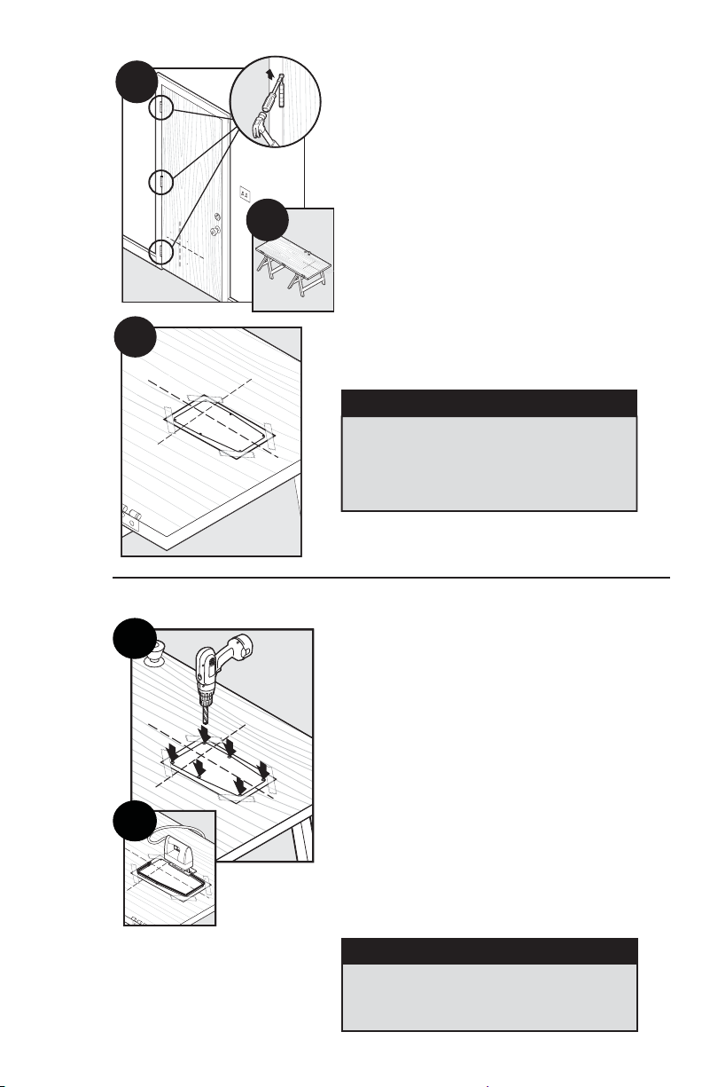
Step
2
Preparing Door
2A
2B
2A Remove door from hinges.
2B Place on a raised level surface such as
saw horses.
Helpful Tip:
prevent it from moving.
NOTE:
door hanging based on your skill level.
Clamp or weigh down the door to
The pet door can be installed with the
Step
3
2C
2C Match the marked lines on the door with the
shoulder and center lines on the template. Tape
the template in place.
When applying the template there should be a
minimum of 3” (7.6 cm) between the bottom
and sides of the door and the outer edge of the
template to maintain the structural integrity of
the door.
Cut Pet Door Opening
3A
3B
3A Leave template on and drill ⅜” (10 mm) holes
in the inside corners of template. These will be
the pilot holes for the saw blade.
Helpful Tip: Use both hands to hold drill steady and
straight at a 90° angle.
3B Beginning in one of the holes you just drilled,
cut along the template lines. After cutting out the
opening, remove excess template. You may need
to recut to square the opening. This is necessary
for the pet door frame to fi t correctly.
Helpful Tip:
to door material (for example a wood blade for
wood door and metal blade for a metal door).
When cutting use both hands to hold the saw
slow, steady and straight at a 90° angle. This will
prevent the blade from cutting unevenly between
interior and exterior areas of door.
NOTICE
Use a proper saw blade according
Make sure there is nothing underneath the
door where you will be drilling the holes or
cutting out opening.
8 1-800-732-2677
NOTICE
Page 9
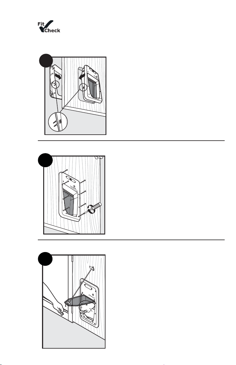
Step
4
Install Pet Door
Before putting away the jigsaw, place the interior frame (frame with the
fl ap) inside the cut out and check the fi t. Then, place the exterior frame into the
underside of the door to check the fi t. If frames do not fi t inside the opening, you
may need to recut to square opening before proceeding with installation.
4
4 Re-hang door and place interior frame with
fl ap inside cut-out of interior door. Place exterior
frame on exterior of door and press fi rmly against
interior frame and exterior frame with both hands.
Continue to press while moving hands from bottom
to top of frames until alignment tabs connect and
both frames are fi rmly in place.
Step
5
Step
6
Insert Screws
5
Train Your Pet
6
Helpful Tip:
interior frame and door to keep in place while
positioning the exterior frame.
5 Thread mounting screws through interior
frame and align with exterior frame. Tighten with
screwdriver. DO NOT OVERTIGHTEN.
Helpful Tip:
low torque.
NOTE:
placement holes and Large SmartDoor
screw placement holes.
6 Tape the fl ap open to help your pet become
familiar with the pet door opening. When your pet
is more comfortable let the fl ap down and operate
the SmartDoor™ in UNLOCKED Mode encouraging
your pet to push through the fl ap. Once your
pet is comfortable entering and exiting through
the closed fl ap, set SmartDoor™ to AUTOMATIC
Mode and operate with your pet’s programmed
SmartKey™. Walk your pet up to the SmartDoor™
until the SmartKey
Repeat training your pet to walk up to SmartDoor™
and push open fl ap to the other side.
Helpful Tip:
push through the SmartDoor™ fl ap.
Use painters’ tape across SmartDoor™’s
If using an electric screwdriver, set on
Small SmartDoor™ has four screw
™
is detected and fl ap unlocks.
Try treats to encourage your pet to
™
has eight
www.petsafe.net 9
Page 10
NOTE:
The SmartDoor™ is designed with an electric motor to release and unlock fl ap when a
SmartKey™ is detected. Do not allow your pet to run or charge through the SmartDoor
variable radio-frequency interferences it could take several seconds for SmartKey
to read properly and SmartDoor™’s fl ap to unlock.
™
. Due to
™
’s unique code
SET
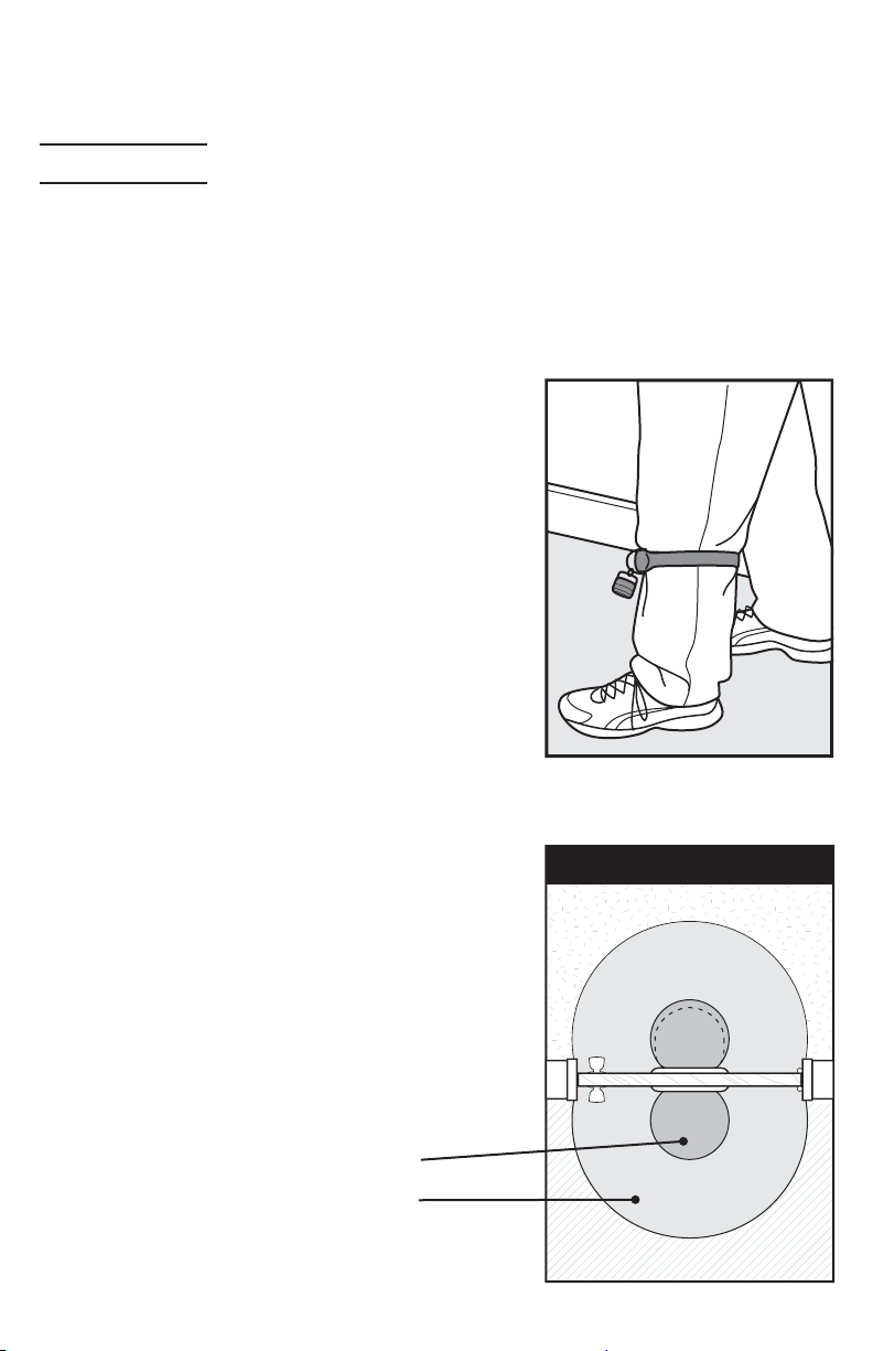
A. Setting SmartDoor™’s Sensitivity Level
It is necessary to set your SmartDoor™’s sensitivity level so your pet’s SmartKey™ works properly
due to location or application material, such as radio-frequency interferences, wood or metal
door installations.
To begin, it is recommended to use the split ring (included) to attach the SmartKey™ to the D-ring
on your pet’s collar. Also do not use metal tags as the additional metal can cause radio-frequency
interference and hinder the detection of your pet’s SmartKey™. Now, continue with the following
“product in use” steps:
1. Put the dog’s collar on your leg just below your knee. Tape
may be used to secure the collar, if necessary. See A.
2.
Stand directly in front of the SmartDoor™ so the SmartKey™
is approximately 2.5 feet (76 cm) from the SmartDoor™.
3. Put the SmartDoor™ in the UNLOCKED Mode. (See page 6
for operational instructions).
4. Put the SmartDoor™ in the Sensitivity Test Mode by
holding down the MODE-RESET and LEARN buttons at the
same time until all three lights fl ash once.
5. Turn the Sensitivity Knob counter clockwise to the
minimum position, then turn the Sensitivity Knob
clockwise until all lights begin to fl ash again.
6. Slowly continue to adjust the Sensitivity Knob clockwise
until you see a minimum of six consecutive fl ashes and
stop adjusting. Do not adjust higher than necessary.
7. Put the SmartDoor™ in AUTOMATIC Mode and step away
at least 10 feet (3 m), allowing the door to automatically
lock. This may take up to fi fteen seconds after the
SmartKey™ no longer is detected.
8. Now confi rm the sensitivity level by approaching the
SmartDoor™ again. The door should unlock when you
step within approximately 2 feet (60 cm) in front of the
SmartDoor™.
B. Understanding Sensitivity and the
Active Area
The Active Area is the area where the SmartDoor™ will
consistently open based on your adjustment of the
sensitivity level. In the Fringe Area the SmartDoor™ may
open inconsistently due to variables of radio-frequency
interferences or refl ections. In the Inactive Area the door
will generally not unlock automatically. See B.
You may see slight differences between Outside and Inside
Active Areas due to radio-frequency interferences.
A.
Door - Top View
B.
Outside
Inactive
Fringe
Active
Depending on location
and application
~ 2.5 feet (76 cm)
~ 6 feet (183 cm)
10 1-800-732-2677
Inside
Active
Fringe
Inactive
Page 11
C. Programming a New SmartKey
To reduce error while programming, remove the RFA-67 battery from all programmed SmartKeys™
except the one you are programming. Press and hold the LEARN button until the green light
illuminates and begins to fl ash, now release the button. Bring the SmartKey™ directly below the
green light and the light will stop fl ashing and illuminate for two seconds. Now your new SmartKey™
has been programmed and added to memory. Up to fi ve different SmartKeys™ can be added, one at
a time.
™
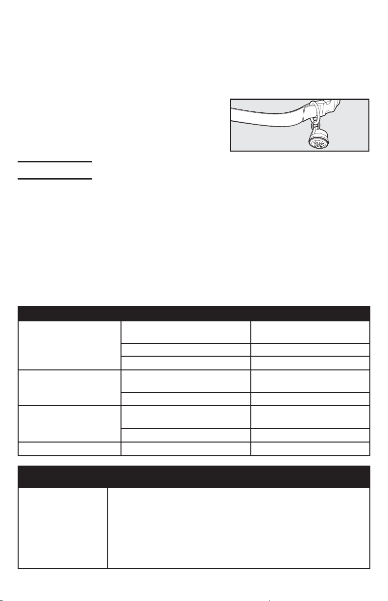
D. Attach the SmartKey™ to the Pet’s Collar
A split key ring has been provided to attach to your pet’s
collar and should hang under the pet’s neck.
The SmartDoor™ includes (one) SmartKey™ which comes
pre-programmed and ready to use.
OPERATE
Operating Your SmartDoor
LOCKED MODE – Does not allow entry or exit for any pet. The SmartDoor™ ships from the factory
in LOCKED MODE and when batteries are placed in the SmartDoor
set: hold the MODE-RESET button until the red light illuminates and release when selected.
UNLOCKED MODE – Allows entry and exit for all pets. To set: hold the MODE-RESET button until
the green light illuminates and release when selected.
AUTOMATIC MODE – Allows entry and exit for a pet wearing a programmed SmartKey™; up
to fi ve SmartKeys™ can be programmed into one SmartDoor™ for selective entry and exit during
automatic mode. To set: hold the MODE-RESET button until the yellow light illuminates and
release when selected.
NOTE:
If at any time the red light remains illuminated, replace with a set of fresh batteries. If that
does not reset the red light, please call our Customer Care Center for additional help.
Illuminating Color Condition Pet Door Status
Solid only for two seconds after
RED
GREEN
YELLOW
RED, GREEN AND YELLOW
selecting LOCKED Mode
Flashing Low battery alert
Constant solid Internal failure has occurred
Solid only for two seconds after
selecting UNLOCKED Mode
Flashing Learn Mode
Solid only for two seconds after
selecting AUTOMATIC Mode
Flashing Error alert
Flashing at the same time Sensitivity Test Mode
™
™
, it will enter LOCKED MODE. To
LOCKED Mode
UNLOCKED Mode
AUTOMATIC Mode
Troubleshooting
SmartDoor™ does
not respond to the
presence of the
SmartKey™ when my
pet is directly in front
of the SmartDoor™
within three seconds
www.petsafe.net 11
• Check that the SmartDoor™ is in AUTOMATIC Mode.
• Check that the SmartKey™ has been programmed to the SmartDoor™.
• Check sensitivity level has been properly set, see page 10.
• Check that the RFA-67 battery in the SmartKey™ is screwed in tightly.
• Check that the batteries in the SmartDoor™ are fresh.
• If the condition persists, check that there are no radio-frequency
transmitting devices or electronic devices that radiate electrical
energy, which may interfere with the operation of the SmartDoor
™
.
Page 12

Yellow light is fl ashing • Obstruction to the flap has been detected.
• Press the MODE-RESET button to cause the SmartDoor™ to attempt
to lock the flap. Clear any obstructions that keep the flap from
locking. When the flap successfully locks, normal operation is resumed.
™
• If your large SmartDoor
does not close properly, you can purchase
an additional magnet kit to help center flap due to constant wind
or a variance between indoor and outdoor pressure. Please call the
Customer Care Center for further assistance.
Red light remains
illuminated (internal
failure has occurred)
• Remove batteries and replace them with a fresh set of batteries. If
that does not reset the red light, please call Customer Care Center at
1-800-732-2677 for additional help.
Red light is fl ashing • Low battery indicator, replace batteries.
Red, green and yellow
lights are fl ashing
• Sensitivity set mode has been activated. It will automatically
de-activate in thirty minutes, or can be immediately de-activated by
pressing the MODE-RESET button once.
Revert SmartKey™ to Default Factory Setting
The SmartDoor™ can be cleared of all additional programmed SmartKey™ EXCEPT the one included
from the factory. To do this, fi rst take out batteries from battery compartment. Then, as you place
batteries back into the battery compartment, hold down the LEARN button. When LEARN button
is held and the last battery is in place, the red and green lights will illuminate three times. Now,
all SmartKeys™ programmed to the SmartDoor™ have been cleared except the one SmartKey™
included with your SmartDoor™.
Clear SmartKey™ Memory
The SmartDoor™ can be cleared of all programmed SmartKeys™, even the one included from the
factory. To do this, fi rst remove batteries from battery compartment. Then, as you place batter-
ies back into the battery compartment, hold down the MODE-RESET button. When MODE-RESET
button is held and the last battery is in place, the red and yellow lights will illuminate three times.
Now all SmartKeys™ have been cleared.
______________________________________________________________________________
Replacement Parts and Accessories
To purchase replacement parts for your PetSafe® SmartDoor™, contact the Customer Care Center
at 1-800-732-2677 or visit our website at www.petsafe.net to locate a retailer near you.
Customer Care International
Canada: 1-800-732-2677
United Kingdom: 0800 046 1414
Europe: 00 800 18 18 20 20
Component Part Number
SmartKey
PetSafe
™
®
RFA-67 Battery RFA-67
Small Replacement Flap CPA11-11580/MPA00-12830
Large Replacement Flap CPA11-11579/MPA00-12829
Small SmartDoor
Large SmartDoor
™
Hardware Kit CPA00-11617/MPA00-12814
™
Hardware Kit CPA00-11618/MPA00-12815
Small Wall Conversion Kit MPA11-12019
Large Wall Conversion Kit MPA11-12020
Large Extension Tunnel CPA00-12021/MPA00-12820
Small Wall Conversion – Hardware Replacement Kit CPA00-12054/MPA00-12821
Large Wall Conversion – Hardware Replacement Kit CPA00-12055/MPA00-12822
12 1-800-732-2677
Australia: 1800 786 608
New Zealand: 0800 543 054
PAC11-11405
Page 13

This product has the benefi t of a limited manufacturer’s warranty. Details of the warranty
applicable to this product and its terms can be found at www.petsafe.net and/or are available by
sending a stamped addressed envelope to PetSafe® Ltd. Redthorn House, Unit 9, Chorley West
Business Park, Ackhurst Road, Chorley, Lancashire PR7 1NL, United Kingdom.
______________________________________________________________________________
Terms of Use and Limitation of Liability
1. Terms of Use
This Product is offered to you conditioned upon your acceptance without modification of the
terms, conditions and notices contained herein. Usage of this Product implies acceptance of all
such terms, conditions, and notices.
2. Proper Use
This Product is designed for use with pets where training is desired. The specific temperament
of your pet may not work with this Product. If you are unsure whether this is appropriate for
your pet, please consult your veterinarian or certified trainer. Proper use includes reviewing
the entire Operating Guide provided with your Product and any specific Caution statements.
3. No Unlawful or Prohibited Use
This Product is designed for use with pets only. This pet training device is not intended to
harm, injure, or provoke. Using this Product in a way that is not intended could result in
violation of Federal, State or local laws.
4. Limitation of Liability
In no event shall Radio Systems
incidental, special or consequential damages, or any damages whatsoever arising out of or
connected with the use or misuse of this Product. Buyer assumes all risks and liability from
the use of this Product.
5. Modification of Terms and Conditions
Radio Systems Corporation reserves the right to change the terms, conditions and notices
under which this Product is offered.
®
Corporation be liable for any direct, indirect, punitive,
Perchlorate Battery
Perchlorate Material – special handling may apply. See www.dtsc.ca.gov/hazardouswaste/
perchlorate.
Important Recycling Advice
Please respect the Waste Electrical and Electronic Equipment regulations in your country. This
equipment must be recycled. If you no longer require this equipment, do not place it in the normal
municipal waste system. Please return it to where it was purchased in
placed in our recycling system. If this is not possible, please contact the Customer Care
Center for further information.
order that it can be
Battery Disposal
Separate collection of spent batteries is required in many regions; check the regulations in your area
before discarding spent batteries.
SmartDoor
This device operates on four Alkaline batteries of the type LR20/D-cell with a 1.5 Volt, 18,000 mAH
capacity. Replace only with the equivalent batteries.
SmartKey
This device operates on two Lithium batteries of the type CR2032 with a 3 Volt, 220 mAH capacity.
Replace only with equivalent battery available from the Customer Care Center.
Please see page 6 for instructions on how to remove the batteries from these products for
separate disposal.
______________________________________________________________________________
Compliance
FCC/Canada
This Class B digital apparatus complies with Canadian ICES-003. This equipment has been tested
and found to comply with the limits for a Class B digital device, pursuant to Part 15 of the FCC
Rules. These limits are designed to provide reasonable protection against harmful interference
when the equipment is operated in a residential environment. This equipment generates, uses,
and can radiate radio frequency energy and, if not installed and used in accordance with the
www.petsafe.net 13
™
:
™
:
Page 14

instruction guide, may cause harmful interference to radio communications. However, there is
no guarantee that interference will not occur in a practical installation. If this equipment causes
harmful interference to radio or television reception, which can be determined by turning the
equipment off and on, the user is encouraged to try to correct the interference by one or more of
the following measures:
• Relocate the interfered receiving antenna.
• Increase the separation between the equipment and receiver.
• Connect the equipment into an outlet on a circuit different to that to which the receiver
is connected.
• Contact the Customer Care Center.
This device complies with Industry Canada Rules. This device complies with part 15 of the FCC
Rules. Operation is subject to the following two conditions: (1) This device may not cause harmful
interference, and (2) this device must accept any interference received, including interference that
may cause undesired operation.
Unauthorized changes or modifi cations to the equipment, not approved by Radio Systems
®
Corporation, could result in not meeting compliance with FCC regulations and could void the user’s
authority to operate the equipment.
This equipment has been tested and found to comply with relevant EU Electromagnetic
Compatibility, Low Voltage and R&TTE Directives. Before using this equipment outside the EU
countries, check with the relevant local R&TTE authority. Unauthorized changes or modifi cations to
the equipment that are not approved by Radio Systems® Corporation are in violation of EU R&TTE
regulations, could void the user’s authority to operate the equipment, and void the warranty.
The Declaration of Conformity can be found at: http://www.petsafe.net/customercare/eu_docs.php.
Australia
This device complies with the applicable EMC requirements specifi ed by the ACMA (Australian
Communications and Media Authority).
14 1-800-732-2677
Page 15

Importante information de sécurité
Explication des mots et symboles d'alerte utilisés dans ce guide
Voici un symbole d'alerte de sécurité. Il signifi e un risque potentiel de
blessures corporelles. Suivez tous les messages de sécurité suivant ce
symbole pour éviter toutes blessures corporelles ou même la mort.
AVERTISSEMENT
ATTENTION
AVIS
AVERTISSEMENT
AVERTISSEMENT indique une situation dangereuse qui, si
non évitée, pourrait résulter en des blessures sérieuses ou
même la mort.
ATTENTION, utilisé avec un symbole d'alerte de sécurité,
indique une situation dangereuse qui, si elle n'est
pas évitée, pourrait entraîner des blessures légères à
modérées.
AVIS, indique les pratiques qui ne sont pas relatives aux
blessures corporelles.
•
Lorsque des enfants sont présents dans la maison, il est important
de toujours surveiller la chatière pendant les activités de ceux-ci.
La chatière pourrait être mal utilisée par un enfant, ce dernier
pouvant alors faire face à des risques potentiels se situant
de l'autre côté de la chatière. Les acheteurs et propriétaires
possédant des piscines devraient s'assurer que la chatière est
toujours surveillée et que la piscine est entourée d'une barrière
adéquate y empêchant l'accès. Si un nouveau risque est créé à
l'intérieur ou à l'extérieur de votre résidence, risque pouvant être
accéder par la chatière, Radio Systems® Corporation recommande
de sécuriser l'accès à ce danger adéquatement ou de retirer la
chatière. Le panneau de fermeture ou le verrou, si applicable, est
fourni en un but esthétique et d'économie d'énergie et ne doit
pas être utilisé comme un dispositif de sécurité. Radio Systems®
Corporation ne peut être tenu responsable d'intrusion involontaire
et il est entendu que l'acheteur de ce produit accepte la totale
responsabilité de la surveillance de l'ouverture qu'il créé ainsi.
• Outils électriques. Risques de blessures sérieuses; suivez toutes
les instructions de sécurité de vos outils électriques. Portez
toujours des lunettes de sécurité.
ATTENTION
AVIS
www.petsafe.net 15
L'utilisateur, avant l'installation, doit être familier avec les codes
de construction pouvant affecter l'installation de la chatière
et déterminer, en conjonction un entrepreneur autorisé, la
pertinence de son installation. Cette chatière n'est pas une sortie
d'incendie. Il est important pour le propriétaire et l'entrepreneur
de considérer tous les risques présents à l'intérieur comme à
l'extérieur de la chatière, ainsi que tous les risques pouvant être
créés suite à des changements effectués sur votre propriété et
comment l'existence et l'utilisation de la chatière, y compris une
mauvaise utilisation de celle-ci, peut représenter un danger.
•
Conservez ces instructions avec vos papiers importants; en cas de
vente de votre propriété, assurez-vous de transférer ces instructions
au nouveau propriétaire.
• Des changements ou modifi cations non-autorisées peuvent
annuler l'autorité de l'utilisateur pour l'utilisation de cet
équipement et rendre la garantie nulle.
Page 16

®
Merci d'avoir choisi la marque PetSafe
. Vous et votre animal méritez une camaraderie
qui comprend des moments mémorables et une franche compréhension. Nos produits et
outils d'entraînement favorise un style de vie de protection, d'enseignement et d'amour tous essentiels pour infl uencer de bons souvenirs pour la vie. Si vous avez des questions
sur nos produits ou l'entraînement de votre animal, veuillez visiter note site Internet au
www.petsafe.net
ou contactez notre service à la clientèle.
GARANTIE DU PRODUIT
Pour obtenir la protection maximale de votre garantie, veuillez enregistrer votre produit
moins de 30 jours suivant l'achat au
www.petsafe.net
. En enregistrant votre produit
moins de 30 jours après la date d'achat et en conservant votre reçu, vous bénéfi cierez
d'une réponse plus rapide du service à la clientèle s'il advenait que vous deviez
communiquer avec eux. Encore plus important, PetSafe® ne communiquera et ne vendra
jamais vos informations personnelles à qui que se soit. Consultez l'information complète
de la garantie au
www.petsafe.net
.
________________________________________________________________________________
Table des matières
Composants .................................................................................................................... 17
Outils requis ................................................................................................................... 17
Comment fonctionne la SmartDoor™ ................................................................................... 17
Installation de la SmartDoor™ dans un mur avec la trousse de conversion SmartDoor™ .............. 17
Défi nitions clefs ............................................................................................................... 18
PRÉPARATION
A. Installez les piles dans la SmartDoor™ ......................................................................... 19
B. Installez la pile dans la SmartKey
C. Vérifi ez les différents modes de fonctionnement avant l'installation indicateurs
de fonctionnement ................................................................................................... 19
D. Vérifi cation l'endroit de la SmartDoor avant l'installation ............................................... 20
INSTALLATION
Installation de votre SmartDoor™ .................................................................................... 21
RÉGLAGE
A. Réglage du niveau de sensibilité de la SmartDoor™ ........................................................ 23
B. Compréhension la sensibilité et de la zone active ......................................................... 24
C. Programmation d'une nouvelle SmartKey
D. Fixer la SmartKey™ au collier de votre animal ............................................................... 25
FONCTIONNEMENT
Fonctionnement de votre SmartDoor™ ............................................................................. 25
Schéma de dépannage ..................................................................................................... 26
Régler la SmartKey™ aux réglages par défaut ....................................................................... 26
Effacer la mémoire SmartKey™ ........................................................................................... 26
Pièces de remplacement et accessoires ............................................................................... 26
Service à la clientèle International ..................................................................................... 27
Conditions d'utilisation et limitation de responsabilité ........................................................... 27
Pile perchlorate ...............................................................................................................27
Avis de recyclage importante ............................................................................................ 28
Mise au rebut de pile ........................................................................................................ 28
Conformité .....................................................................................................................28
™
.............................................................................. 19
™
.................................................................. 25
16 1-800-732-2677
Page 17

Composants
Vous retrouverez, à l'intérieur du compartiment
à piles, la SmartKey
mise de montage ainsi qu'un porte-clefs
Mode d'emploi
Cadre intérieur
avec rabat
Gabarit de coupe
Cadre extérieur
Outils nécessaires
™
, une pile RFA-67, des
™
SmartKey
Vis de montage
(petite porte, 4 mcx)
(grande porte, 8 mcx)
Porte-clefs
• Scie sauteuse et scie
passe-partout
• Perceuse électrique
• Mèches de 10 mm (⅜ po)
• Tournevis Phillips
• 4 piles D (LR20) (requises)
• Niveau
• Ruban à mesurer
• Crayon
• Corde
Pile
(PetSafe
RFA-67)
®
____________________________________________________________________________________________________________________________________________
Comment fonctionne la SmartDoor
À l'aide de technologie radiofréquences, la SmartDoor™ lit le signal unique de la SmartKey™
et déclenche l'alimentation de la pile conçue pour déverrouiller le rabat afi n que votre animal
de compagnie puisse entrer et sortir comme il le veut. Lorsque la SmartDoor™ ne détecte
plus la SmartKey™ de votre animal, le volet se verrouillera automatiquement en place. La
SmartDoor™ peut détecter jusqu'à cinq SmartKey™ programmées et fonctionne en deux
modes différents : mode complètement verrouillé et mode déverrouillé.
™
Installation de la SmartDoor™ dans un mur avec la
trousse de conversion SmartDoor
Les trousses de conversion SmartDoor™ sont disponibles pour des installations murales. Cette
trousse de rallonge murale vous permet de faire ressortir les zones exposées, donnant ainsi à
votre installation un fi ni franc et régulier. Pour les constructions en brique, en béton ou en blocs,
une rallonge supplémentaire est disponible pour la grande trousse de conversion. Remarque :
la petite trousse de conversion SmartDoor
rallonge supplémentaire n'est nécessaire. Vous pouvez faire l'achat d'une trousse de conversion
SmartDoor
avec notre Service à la clientèle. Consultez la section « Pièces de remplacement » à la page 27.
www.petsafe.net 17
™
par l'entremise de l'un de nos sites Web au www.petsafe.net ou en communiquant
™
est conçue pour s'encastrer dans la brique; aucune
™
Page 18

Défi nitions clefs
Technologie radiofréquences - L'utilisation d'un signal radiofréquence peut être transmis sans fi ls.
SmartKey™ - Une SmartKey™ est un émetteur fonctionnant à pile qui envoie un code unique à la SmartDoor
SmartDoor™ - La SmartDoor™ est un récepteur intelligent utilisant une antenne interne pour
recevoir le code unique™ SmartKey contrôlant l'entrée et la sortie d'un animal en particulier.
SmartDoor™ Rabat - Le rabat de la SmartDoor™ est un rabat en plastique résistant aux
intempéries et protégé contre les rayons UV du soleil.
Antenne - L'antenne est située à l'intérieur de la SmartDoor
™
et reçoit les radio signaux de la SmartKey™.
La SmartKey™ doit être située assez près de l'antenne afi n que celle-ci puisse lire le code unique.
Brouillage aux radiofréquences - Le brouillage aux radiofréquences est dû à la provenance
d'autres signaux radiofréquences provenant d'appareils domestiques ou de produits électroniques
communs affectant négativement la capacité du SmartDoor™ à recevoir le signal provenant d'une
SmartKey™. Le brouillage radiofréquences ou « bruit » peut provenir de différentes sources. Le
brouillage peut être minime, constant ou constamment changeant selon l'utilisation et la proximité
des autres appareils domestiques lorsque la SmartDoor
™
est utilisée. Une distance de 60 cm (2 pi)
est recommandée entre les appareils domestiques et produits électroniques et la SmartDoor
Bouton de Sensitivity [sensibilité] - Le bouton de sensibilité est installé de façon pratique à
l'intérieur du cadre de la SmartDoor™. La sensibilité de la SmartDoor™peut aisément être ajustée
selon les interférences habituelles et les facteurs environnants, afi n d'obtenir un fonctionnement
optimal de la SmartDoor™.
Niveau de sensibilité - Le niveau de sensibilité peut être ajusté en tournant le bouton de
sensibilité de minimum vers maximum, dépendamment du brouillage aux radiofréquences et
l'application ou le lieu de la SmartDoor™. Réglez en usine, le bouton de sensibilité ne devrait pas
être ajusté avant que l'installation ne soit terminée. Par exemple, le niveau de sensibilité pourrait
devoir être augmenté si la SmartDoor
™
est installée dans une porte métallique. Consultez la page
24 pour plus d'information sur la façon d'ajuster la sensibilité.
Bouton MODE-RESET [MODE RÉINITIALISATION] - Sélectionnez aisément le Mode
opérationnel de votre SmartDoor
™
en pressant le bouton MODE RÉINITIALISATION afi n de
naviguer dans les sélections de fonctionnement : VERROUILLÉ, DÉVERROUILLÉ ou AUTOMATIQUE.
Bouton LEARN [APPRENDRE] - Le bouton APPRENDRE programme une SmartKey™ avec un
code unique afi n qu'elle puisse être lue par la SmartDoor™. (Une) SmartKey™ arrive programmée et
prête à l'emploi. Vous pouvez programmer jusqu'à cinq SmartKey™ (chacune vendue séparément)
pour une SmartDoor™.
Modes de fonctionnement
Mode LOCKED [VERROUILLÉ] - Le rabat SmartDoor™ est verrouillé et ne permet pas l'accès
ou la sortie, peu importe l'animal.
Mode UNLOCKED [DÉVERROUILLÉ] - Le rabat SmartDoor™ est déverrouillé et permet à tous
les animaux d'entrer et de sortir.
Mode AUTOMATIC [AUTOMATIQUE] - Le rabat SmartDoor™ est verrouillé électroniquement
et ne permet l'entrée et la sortie qu'aux animaux portant une SmartKey™ programmée.
Compartiment à pile
- Le compartiment à pile est situé à l'intérieur du cadre et
nécessite (quatre) piles D (LR20). Vous retrouverez les vis de montage, le porte-clefs, la
SmartKey™ et la pile RFA-67 dans le compartiment de pile.
Pile RFA-67
- La pile RFA-67 est remplaçable et alimente la SmartKey™. Des piles
supplémentaires RFA-67 sont disponibles chez les détaillants ou en communiquant avec
le service à la clientèle de PetSafe® ou en visitant le www.petsafe.net. La durée de vie
normale de la pile RFA-67 et d'environ six mois.
™
.
™
.
Dimension extérieure du cadre
Taille de l'ouverture
- Découpe de l'ouverture dans la porte du propriétaire pour
- Dimensions générales de la chatière
l'installation et l'ajustement adéquat de la chatière
Taille du rabat de remplacement
- Taille générale du rabat lorsque celui-ci est retiré
de la chatière
Taille de l'ouverture par rabat
- Espace utilisé par le rabat pour permettre l'entrer et
la sortie de l'animal à travers la chatière
Cadre intérieur
Cadre extérieur
- Cadre de la chatière sur la partie intérieur de la maison
- Cadre de la chatière sur l'extérieur de la maison
18 1-800-732-2677
Page 19

PRÉPARATION
Préparation de votre SmartDoor
NE FAIRE AUCUNE COUPE OU INSTALLATION TANT QUE LES ÉTAPES A À D CI-DESSOUS
N'ONT PAS ÉTÉ COMPLÉTÉES. NE RETIREZ PAS L'AUTOCOLLANT DE SENSIBILITÉ TANT
QUE L'INSTALLATION N'EST PAS TERMINÉE.
A. Installez les piles dans la SmartDoor
1. À l'aide d'un tournevis Phillips, retirez les deux vis
retenant le couvercle du compartiment à piles.
2. Retirez le couvercle du compartiment à piles.
3. Consultez l'intérieur du couvercle du compartiment
à piles pour installer correctement les quatre piles
D (LR20).
4. Réinstallez le couvercle du compartiment à piles à
l'aide des deux vis.
5. Lorsque les piles sont installées dans la SmartDoor™
électronique, le voyant rouge s'illuminera pendant
deux secondes et le rabat se déplacera en position
verrouillée, à moins que le rabat ne soit déjà en
position verrouillé.
REMARQUE :
pour que le rabat soit adéquatement centré et qu'il
fonctionne correctement.
la porte doit être en position verticale
B. Installez a pile dans la SmartKey
1. Installez la pile RFA-67 PetSafe® dans le bas de
la SmartKey™.
2. À l'aide d'une pièce de monnaie, faites un quart
de tour dans le sens horaire pour verrouiller la pile
RFA-67 PetSafe®.
REMARQUE :
qui clignotera lorsque la pile RFA-67 PetSafe® sera
faible; la pile devra alors être remplacée le plus
rapidement possible.
la SmartKey™ possède un voyant rouge
™
™
™
C. Vérifi ez les différents modes de fonctionnement avant l'installation
indicateurs de fonctionnement
SmartDoor™ électronique
A. Bouton de sensibilité
Voyant indicateur rouge
B.
pour verrouillé ou pile faible
C. Voyant indicateur vert pour
déverrouillé ou Mode
programmation
Voyant indicateur jaune pour
D.
Mode automatique ou erreur
E. Bouton de sélection Mode
réinitialisation
Bouton Mode programmation
F.
www.petsafe.net 19
A
B C D E F
Page 20

• Pour s'assurer que les réglages fonctionnent correctement, pressez et tenez le bouton MODE
RÉINITIALISATION jusqu'à ce que tous les modes de fonctionnement soient apparus et aient fait
allumés chacun une fois le voyant rouge, vert et jaune.
Modes de fonctionnement
MODE VERROUILLÉ - Le mode verrouillé n'autorise l'entrée ou la sortie à aucun
animal. La SmartDoor™ est expédiée de l'usine en MODE VERROUILLÉ et elle entrera
en MODE VERROUILLÉ lorsque Des piles sont installées dans la SmartDoor™. Pour le
réglage : appuyez et tenez le bouton MODE RÉINITIALISATION jusqu'à ce que le voyant
rouge s'allume, vous pouvez ensuite relâchez le bouton une fois la sélection effectuée.
MODE DÉVERROUILLÉ - permet l'entrée et la sortie à tous les animaux. Pour le
réglage : appuyez et tenez le bouton MODE RÉINITIALISATION jusqu'à ce que le voyant
vert s'allume, vous pouvez ensuite relâchez le bouton une fois la sélection effectuée.
MODE AUTOMATIQUE - ne permet l'entrée et la sortie qu'aux animaux portant une SmartKey
programmée™. Pour le réglage : appuyez et tenez le bouton MODE RÉINITIALISATION jusqu'à
ce que le voyant jaune s'allume, vous pouvez ensuite relâchez le bouton une fois la sélection
effectuée. Cinq clefs SmartKey™ peuvent être programmées à une SmartDoor™ pour l'entrée et
la sortie sélective en MODE AUTOMATIQUE.
REMARQUE :
si à tout moment le voyant rouge reste allumé, remplacez les piles. Si cela n'efface
pas le voyant rouge, veuillez contacter notre service à la clientèle pour de l'aide supplémentaire.
Si vous rencontrez un échec dans une des partie de l'étape C, veuillez contacter notre
service à la clientèle pour de l'aide supplémentaire.
D. Vérifi cation l'endroit de la SmartDoor™ avant l'installation
NE RETIREZ PAS L'AUTOCOLLANT DE SENSIBILITÉ TANT QUE L'INSTALLATION DE LA
SMARTDOOR
Il est recommandé de vérifi er, avant l'installation, le fonctionnement adéquat de la
SmartDoor™ dans l'endroit ou le lieu prévu d'utilisation. Vérifi ez contre tout brouillage
aux radiofréquences importants. Une distance de 60 cm (2 pi) est recommandée entre
les appareils domestiques et produits électroniques et le lieu™ où est situé la SmartDoor.
Le brouillage aux radiofréquences détecté par d'autres appareils domestiques ou de
produits électroniques communs affecteront négativement la capacité du SmartDoor™ à
recevoir le signal provenant d'une SmartKey™. Les appareils et produits normalement à
surveiller sont les ordinateurs portables, les téléphones sans fi l, les four micro-ondes, les
téléviseurs, les ouvre-portes de garage, les appareils électroniques portatifs (comme les
téléphones cellulaires, les consoles de jeux et les télécommandes sans fi l).
L'autocollant apposé sur le bouton de sensibilité ne devrait pas être retiré, sauf une
fois l'installation terminée, car le réglage de sensibilité réglé en usine est positionné au
niveau optimal convenant à la majorité des installations.
Il est recommandé d'installer la SmartDoor™ dans un endroit où le vent n'est pas un facteur.
Écart de température toléré pour le fonctionnement : -20,5˚ C à 82˚ C (-5˚ F to 180˚ F). Taux
d'humidité toléré pour le fonctionnement : 0 à 99,9 %.
• Pour vérifi er si la technologie radiofréquences de la SmartDoor
l'endroit et l'application désirée, positionnez SmartDoor™ directement en avant et contre la porte
ou l'application, en position verticale. Après avoir effectué les étapes A à C, ajustez maintenant
la SmartDoor™ en mode AUTOMATIQUE et tenez la SmartKey™ directement à l'avant de la
SmartDoor™. Le rabat de la SmartDoor™ devrait se déverrouillé après environ trois secondes.
Rappelez-vous que la SmartKey™ incluse dans la trousse est déjà programmée à la SmartDoor™.
REMARQUE :
piles (RFA-67) lors de l'exécution de l'étape D, sauf pour la SmartKey™ incluse avec la SmartDoor™.
Si la SmartDoor™ ne se déverrouille pas, déplacez la SmartDoor™ à un autre endroit
et effectuez de nouveau les étapes A à D. Si le test de localisation de la SmartDoor™
ci-dessus ne fonctionne pas, veuillez contacter le service à la clientèle pour de
l'aide supplémentaire.
Une fois les étapes A à D complétées avec succès, votre SmartDoor
™
.
™
fonctionne correctement dans
dans l'éventualité où des SmartKey™ existent déjà dans la maison, retirez toutes les
™
peut être installée.
20 1-800-732-2677
Page 21

INSTALLATION
Installation de votre SmartDoor
Étape
1
Étape
2
Déterminez le lieu d'installation de la chatière
1A
1B
Préparation de la porte
2A
1A
Mesurez la hauteur de l'épaule de votre
animal et faites une marque correspondante
sur la porte.
1B
Déterminez l'endroit de la chatière.
Dessinez, à l'aide d'un niveau, une ligne
centrale verticale à partir de la ligne
désignant la hauteur de l'épaule.
Si la porte du propriétaire ou toute autre partie
impliquée n'est pas au niveau, la chatière elle
doit l'être afi n de se rabattre correctement.
2A
Retirez les charnières de la porte.
2B
Déposez-la sur une surface soulevée au
niveau comme un chevalet de menuisier.
Astuce utile : Attachez ou déposez un poids
sur la porte afi n qu'elle ne bouge pas.
™
AVIS
REMARQUE :
2B
2C
www.petsafe.net 21
avec la porte en place, selon votre niveau
de compétence.
2C
Faites correspondre les lignes marquées
sur la porte avec les lignes d'épaule et
centrales sur le gabarit. Fixez la gabarit en
place à l'aide du ruban.
Lorsque vous fi xez le gabarit, un espace d'au
moins 7,6 cm (3 po) doit être présent entre le
bas et les côtés de la porte et le coin supérieur
extérieur du gabarit; cela permettra de
maintenir l'intégralité structurel de la porte.
l
a chatière peut être installée
AVIS
Page 22

Étape
3
Coupez l'ouverture pour la chatière
3A
3B
3A Laissez le gabarit en place et percez des
trous de 10 mm (⅜ po) à l'intérieur des coins de
celui-ci. Ceux-ci serviront de trous de guidage
pour la scie sauteuse.
Astuce utile : Utilisez vos deux mains afi n que
la perceuse soit stable et droite à un angle
de 90°.
3B En commençant dans un des trous que vous
venez tout juste de percer, coupez le long des
lignes du gabarit. Une fois l'ouverture coupée,
retirez l'excès de gabarit. Vous pourriez devoir
recouper afi n que l'ouverture soit à angle droit.
Cela est nécessaire pour que le cadre de la
chatière s'ajuste correctement.
Astuces utile :
au matériel de fabrication de votre porte (par
exemple, une lame à bois pour une porte en bois
et une lame à métal pour une porte métallique).
Pendant la coupe, utilisez vos deux mains pour
couper lentement, régulièrement et à un angle
de 90°. Cela empêchera aussi la lame de couper
de façon inégale entre l'intérieur et l'extérieur de
la porte.
Assurez-vous qu'il n'y a rien en-dessous de
la porte lorsque vous percerez les trous ou
couperez l'ouverture.
utilisez une lame de scie convenant
AVIS
Étape
4
22 1-800-732-2677
Installation de la chatière
avec rabat) dans l'ouverture et vérifi ez l'ajustement. Placez ensuite le cadre
extérieur sur le revers de la porte pour vérifi er l'ajustement. Si les cadres n'entrent
pas dans l'ouverture, vous pourriez devoir recouper l'ouverture à angle droit avant
de procéder à l'installation.
4
Avant de déposer la scie sauteuse, installez le cadre intérieur (cadre
4 Réinstallez la porte et le cadre intérieur avec
le rabat dans l'ouverture de la porte intérieure.
Installez le cadre extérieur sur l'extérieur de la
porte et, à l'aide de vos deux mains, pressez
fermement contre le cadre intérieur et extérieur.
Continuez d'appuyer tout en déplaçant vos mains
du haut vers le bas des cadres, jusqu'à ce que les
onglets d'alignement s'enclenchent et que les deux
cadres soient fermement insérés.
Astuces utile : utilisez un ruban de peintre à travers
l'intérieur du cadre SmartDoor™ et de la porte
afi n de les tenir ensemble pendant que vous
positionnez le cadre extérieur.
Page 23

Étape
5
Insérez les vis
5
5 Vissez les vis dans le cadre intérieur et alignez-
les avec le cadre extérieur. Serrez à l'aide d'un
tournevis. NE PAS TROP SERRER.
Astuces utile :
électrique, réglez-le à un couple de serrage faible.
REMARQUE :
trous d'installation à quatre vis et la SmartDoor™
large est pourvue de trous d'installation à huit vis.
si vous utilisez un tournevis
la petite SmartDoor™ est pourvue de
Étape
6
REMARQUE :
rabat lorsqu'une SmartKey™ est détectée. Ne laissez pas votre animal courir ou s'élancer vers
la SmartDoor™. À cause des brouillages aux radiofréquences, cela pourrait prendre quelques
secondes avant que le code unique SmartKey™’e soit lu correctement, permettant le déverrouillage
de la SmartDoor™.
Entraînement de votre animal
6
la SmartDoor™ est munie d'un moteur électrique pour dégager et déverrouiller le
6 Faites tenir votre rabat ouvert à l'aide de
ruban afi n que votre animal se familiarise
avec l'ouverture de la chatière. Lorsqu'il s'est
familiarisé, abaissez le rabat faites fonctionner
la SmartDoor
encourageant ainsi votre animal à pousser le
rabat. Lorsque votre animal de compagnie s'est
familiarisé avec l'ouverture et la fermeture
du rabat, réglez la SmartDoor™ au Mode
AUTOMATIQUE et utilisez-le en conjonction avec
la SmartKey™ programmée. Amenez votre animal
à la SmartDoor™ jusqu'au point où la SmartKey™
est détectée, déverrouillant le rabat. Répétez
l'entraînement de votre animal à e rendre à la
SmartDoor™ et qu'il pousse le rabat pour se rendre
de l'autre côté.
Astuce utile :
votre animal à pousser le rabat SmartDoor™.
™
en Mode DÉVERROUILLÉ,
utilisez des gâteries pour encourager
RÉGLAGE
A. Réglage du niveau de sensibilité de la SmartDoor
Il est nécessaire de régler le niveau de sensibilité de la SmartDoor™ afi n que la SmartKey™
de votre animal fonctionne correctement, selon le lieu ou le matériel utilisé, comme le
brouillage aux radiofréquences, les portes en bois ou métalliques.
Il est recommandé d'utiliser au départ l'anneau brisé (inclus) pour fi xer la SmartKey™
à l'anneau en D du collier de votre animal. N'utilisez pas d'étiquettes métalliques car
cela pourrait causer des brouillages aux radiofréquences et empêcher la détection de
la SmartKey™ de votre animal. Continuez maintenant à suivre les étapes suivantes
intitulées « Utilisation du produit » :
™
.
www.petsafe.net 23
Page 24

1. Déposez le collier de votre chien sur votre jambe, tout
juste en dessous de votre genou. Un ruban peut être
utilisé pour fi xer le collier, si nécessaire. Voir A.
2. Tenez-vous directement en avant de la SmartDoor™ afi n
que la SmartKey™ se situe à environ 76 cm (2,5 pi) de la
SmartDoor™.
3.
Réglez la SmartDoor™ en Mode DÉVERROUILLÉ. (Consultez
la page 20 pour les instructions de fonctionnement).
4. Réglez la SmartDoor™ en Mode Test de sensibilité
en tenant les boutons MODE RÉINITIALISATION et
APPRENDRE enfoncés en même temps jusqu'à ce que les
trois voyants clignotent une fois.
5. Tournez le bouton de sensibilité dans le sens antihoraire,
en position minimale, et tournez ensuite le bouton de
sensibilité dans le sens horaire jusqu'à ce que tous les
voyants recommencent à clignoter.
6. Continuez de tourner doucement dans le sens horaire
pour ajuster le Bouton de sensibilité jusqu'à ce que six
clignotements consécutifs se produisent; cessez alors
l'ajustement. Ne pas ajuster plus élevé que nécessaire.
7. Mettez la SmartDoor
™
en Mode AUTOMATIQUE et reculez
d'au moins 3 m (10 pi), permettant ainsi la porte de
se verrouiller automatiquement. Cela pourrait prendre
jusqu'à quinze secondes, une fois que la SmartKey
™
n'est
plus détectée.
8. Confi rmez maintenant le niveau de sensibilité en
approchant de la SmartDoor™. La porte devrait se
déverrouiller lorsque vous vous tenez à environ 60 cm (2
pi) à l'avant de la SmartDoor™.
A.
B. Compréhension la sensibilité et de la
zone active
La zone active est la zone où la SmartDoor™ s'ouvrira
B.
Extérieur
automatiquement selon l'ajustement du niveau de
sensibilité. Dans la zone de frange, la SmartDoor™
pourrait s'ouvrir inopinément due aux différents
brouillages aux radiofréquences ou aux réfl exions.
Dans la zone active, la porte ne se verrouillera
généralement pas automatiquement.
Consultez B.
Vous pourriez remarquer de légères différences entre
les zones actives intérieure et extérieure à cause des
brouillages aux radiofréquences.
Selon le lieu
et l'application
~ 76 cm (2,5 pi)
~ 183 cm (6 pi)
Intérieur
24 1-800-732-2677
Porte - Vue de dessus
Inactive
Frange
Active
Active
Frange
Inactive
Page 25

C. Programmation d'une nouvelle SmartKey
Pour réduire le risque d'erreur lors de la programmation, retirez la pile RFA-67 de toutes
les SmartKey™ programmées, sauf celle que vous désirez programmer. Enfoncez et tenez
le bouton APPRENDRE, jusqu'à ce que le voyant vert s'allume et commence à clignoter,
relâchez-le alors. Dirigez la SmartKey™ directement en-dessous du voyant vert, celleci sera alors immédiatement de clignoter et s'allumera pendant deux secondes. Votre
SmartKey™ est maintenant programmée et ajoutée en mémoire. Jusqu'à cinq SmartKey™
peuvent être ajoutées, une à la fois.
™
D. Fixez la SmartKey™ au collier de votre animal
Un anneau brisé est fourni pour fi xer celle-ci au
collier de votre animal et devrait être suspendue
en-dessous de son cou.
™
La SmartDoor
programmée et prête à l'emploi.
comprend (une) SmartKey™ déjà
FONCTIONNEMENT
Fonctionnement de votre SmartDoor
MODE VERROUILLÉ - Le mode verrouillé n'autorise l'entrée ou la sortie à aucun animal. La
SmartDoor™ est expédiée de l'usine en MODE VERROUILLÉ et elle entrera en MODE VERROUILLÉ
lorsque Des piles sont installées dans la SmartDoor™. Pour le réglage : appuyez et tenez le bouton
MODE RÉINITIALISATION jusqu'à ce que le voyant rouge s'allume, vous pouvez ensuite relâchez le
bouton une fois la sélection effectuée.
MODE DÉVERROUILLÉ - permet l'entrée et la sortie à tous les animaux. Pour le réglage :
appuyez et tenez le bouton MODE RÉINITIALISATION jusqu'à ce que le voyant vert s'allume, vous
pouvez ensuite relâchez le bouton une fois la sélection effectuée.
MODE AUTOMATIQUE – Ne permet l'entrée et la sortie qu'aux animaux portant une SmartKey™
programmée; jusqu'à cinq SmartKey™ peuvent être programmées dans une SmartDoor™,
permettant l'entrée et la sortie sélective en mode automatique. Pour le réglage : appuyez et tenez
le bouton MODE RÉINITIALISATION jusqu'à ce que le voyant jaune s'allume, vous pouvez ensuite
relâchez le bouton une fois la sélection effectuée.
REMARQUE :
pas le voyant rouge, veuillez contacter notre service à la clientèle pour de l'aide supplémentaire.
Couleur du voyant Condition Statut de la chatière
ROUGE
VERTE
JAUNE
ROUGE, VERTE ET JAUNE
si à tout moment le voyant rouge reste allumé, remplacez les piles. Si cela n'efface
Continue pendant seulement deux
secondes après la sélection du
mode VERROUILLÉ
Clignotante Avertissement de pile faible
Constamment allumée Une défectuosité interne s'est
Continue pendant seulement deux
secondes après la sélection du
mode DÉVERROUILLÉ
Clignotante Mode Apprendre
Continue pendant seulement deux
secondes après la sélection du
mode AUTOMATIQUE
Clignotante Avertissement d'erreur
Clignotant en même temps Mode Test de sensibilité
™
Mode VERROUILLÉ
produite
Mode DÉVERROUILLÉ
Mode AUTOMATIQUE
www.petsafe.net 25
Page 26

La SmartDoor™
ne répond pas à
la présence de la
SmartKey™ lorsque
mon animal se dirige
en moins de trois
secondes à l'avant de
la SmartDoor
™
.
La lumière jaune
clignote
La lumière rouge
demeure allumée (une
défectuosité interne
s'est produite)
La lumière rouge
clignote
Les lumières rouge,
verte et jaune
clignotent
Dépannage
• Assurez-vous que la SmartDoor
• Assurez-vous que la SmartKey™ a bien été programmée à la
SmartDoor™.
• Assurez-vous que le niveau de sensibilité a été ajusté correctement,
consultez la page 10.
• Assurez-vous que la pile RFA-67 de la SmartKey™ est bien vissée en
place.
• Assurez-vous que les piles de la SmartDoor
• Si le problème persiste, assurez-vous qu'aucun appareil ne transmet
ou ne reflète de radiofréquences ou d'énergie électrique, ce qui
pourrait nuire au bon fonctionnement de la SmartDoor™.
•
Une obstruction a été détectée au rabat.
• Appuyez sur le bouton MODE RÉINITIALISATION pour tenter de
verrouiller le rabat de la SmartDoor™. Dégage toutes obstructions
empêchant le rabat de se verrouiller. Lorsque le rabat se verrouille, le
fonctionnement normale reprend.
• Si votre grande SmartDoor™ ne se ferme pas correctement, vous
pouvez faire l'acquisition d'une trousse magnétique supplémentaire
pour assister le rabat central lors de vent constant ou d'écart entre
la pression intérieure et extérieure. Veuillez contacter le service à la
clientèle pour plus d'aide.
• Retirez les piles et remplacez-les par des nouvelles. Si cela n'efface
pas la lumière rouge, veuillez contacter notre service à la clientèle
pour de l'aide supplémentaire au 1-800-732-2677.
• Indicateur de pile faible, remplacez les piles.
• Le mode de réglage de sensibilité a été actionné. Il se
désactivera automatiquement dans trente minutes ou peut être
désactivé immédiatement en appuyant une fois sur le bouton
MODE RÉINITIALISATION.
™
est en mode AUTOMATIQUE.
™
sont bonnes.
Rétablir la SmartKey™ aux réglages par défaut
Toutes SmartKey™ déjà programmées dans la SmartDoor™ peuvent être effacées À L'EXCEPTION
de celle incluse lors de l'achat. Pour ce faire, vous devez retirer toutes les piles du compartiment
à piles. Ensuite, lorsque vous réinstallez les piles dans le compartiment, tenez le bouton
APPRENDRE. Lorsque le bouton APPRENDRE est maintenu enfoncé et la dernière pile en place,
les lumières rouge et verte clignoteront à trois reprises. Toutes les SmartKey
SmartDoor
Effacer la mémoire SmartKey
™
ont été effacées, à l'exception de celle incluse avec votre SmartDoor™.
™
™
programmées à la
Toutes SmartKey™ déjà programmées dans la SmartDoor™ peuvent être effacées,
y compris celle celle incluse lors de l'achat. Pour ce faire, vous devez retirer toutes
les piles du compartiment à piles. Ensuite, lorsque vous réinstallez les piles dans le
compartiment, tenez le bouton MODE RÉINITIALISATION. Lorsque le bouton MODE
RÉINTIALISATION est maintenu enfoncé et la dernière pile en place, les lumières rouge
et jaune clignoteront à trois reprises. Toutes les SmartKey
______________________________________________________________________________
™
ont été effacées.
Pièces de remplacement et accessoires
Pour faire l'achat de pièces de remplacement pour votre PetSafe® SmartDoor™, contactez le
Service à la clientèle au 1-800-732-2677 ou visitez notre site Internet au www.petsafe.net
pour localiser le détaillant le plus près de chez vous.
26 1-800-732-2677
Page 27

Service à la clientèle International
Canada : 1-800-732-2677
Royaume-Uni : 0800 046 1414
Europe : 00 800 18 18 20 20
Composant Numéro de pièce
SmartKey
Pile PetSafe® RFA-67 RFA-67
Petit rabat de remplacement
Grand rabat de remplacement
Petite trousse de quincaillerie
Grande trousse de quincaillerie
Trousse de conversion murale - petit
Trousse de conversion murale - grand
Tunnel de rallonge - grand
Conversion murale - petit - Trousse de quincaillerie
de remplacement
Conversion murale - grande - Trousse de quincaillerie
de remplacement
Ce produit est pourvu d'une garantie limitée du fabricant. Les détails de la garantie applicable à
ce produit et ainsi que ces termes sont disponibles au www.petsafe.net ou encore en nous faisant
parvenir une enveloppe affranchie à PetSafe
Park, Ackhurst Road, Chorley, Lancashire PR7 1NL, Royaume-Uni.
________________________________________________________________________________________________________
™
Australie : 1800 786 608
Nouvelle-Zélande : 0800 543 054
PAC11-11405
CPA11-11580/MPA00-12830
CPA11-11579/MPA00-12829
CPA00-11617/MPA00-12814
CPA00-11618/MPA00-12815
MPA11-12019
MPA11-12020
CPA00-12021/MPA00-12820
CPA00-12054/MPA00-12821
CPA00-12055/MPA00-12822
®
Ltd. Redthorn House, Unit 9, Chorley West Business
Conditions d'utilisation et limitation de responsabilité
1. Conditions d'utilisation
Ce produit vous est offert conditionnel à votre accord sans qu'aucune modifi cation ne soit
apportée aux termes, conditions et avis contenus aux présentes. Le fait d'utilisation de ce
produit signifi e votre accord à ces termes, conditions et avis.
2. Utilisation adéquate
Ce produit est conçu pour être utilisé avec des animaux où un entraînement est nécessaire.
Le tempérament particulier de votre animal peut ne pas convenir à ce produit. Si vous n'êtes
pas convaincu que cela convienne à votre animal, veuillez consulter votre vétérinaire ou un
entraîneur accrédité. Une utilisation appropriée comprend la révision complète du Mode d'emploi
fournit avec votre produit ainsi que les clauses d'avertissement spécifi ques.
3. Utilisation illicite ou interdite
Ce produit est conçu pour être utilisé avec des animaux seulement. Cet appareil de formation
pour animaux n'est pas conçu pour porter préjudice, blesser ou provoquer. L'utilisation de ce
produit d'une façon autre que celle pour laquelle il a été conçu pourrait résulter en la violation
de lois fédérale, provinciale ou régionale.
4. Limitation de responsabilité
En aucune circonstance Radio Systems® Corporation ne peut être tenu responsable de dommages
directs, indirects, punitifs, accessoires, spéciaux ou consécutifs, ou tout autre dommage quel qu'ils
soient survenant ou relié à l'utilisation ou au mésusage de ce produit. L'acheteur assume tous les
risques et toutes les responsabilités reliées à l'utilisation de ce produit.
5. Modifi cation de ces termes et conditions
Radio Systems Corporation se réserve le droit de modifi er ces termes, conditions et avis sous
lesquels ce produit est offert.
Pile perchlorate
Matériel perchlorate - une manipulation spéciale pourrait s'appliquer. Consultez le site
www.dtsc.ca.gov/hazardouswaste/perchlorate.
www.petsafe.net 27
Page 28

Avis de recyclage importante
Veuillez respecter les normes de déchet d'équipements électrique et électronique de
votre pays. Cet équipement doit être recyclé. Si vous n'utilisez plus ce produit, ne le
déposez pas dans votre système de déchet municipal régulier. Veuillez le retourner où
l'achat a été effectué afi n qu'il soit déposé dans notre système de recyclage. Si ce n'est
pas possible, veuillez contacter notre service à la clientèle pour plus d'informations.
Mise au rebut de pile
La cueillette séparée de piles usagées existe dans plusieurs régions; vérifi ez les
règlements de votre municipalité avant de vous départir de vos piles usagées.
SmartDoor™ :
cet appareil fonctionne avec des piles alcaline de type LR20/D de 1,5 volts, capacité de
18 000 mAH. Remplacez-les seulement par des piles équivalentes.
SmartKey™ :
cet appareil fonctionne avec deux piles au lithium de type R2032 de 3 volts, capacité de
220 mAH. Remplacez-les seulement par des piles équivalentes en contactant le service à
la clientèle.
Consultez la page 19 pour des instructions sur la façon de retirer les piles de ces
produits pour une élimination séparée.
______________________________________________________________________________
Conformité
CC/Canada
Cet appareil numérique de Classe B est conforme avec la norme ICES-003 Canada. Cet
équipement a été testé et a été trouvé conforme avec les limites d'appareil numérique de
Classe B, conformément à la Partie 15 des règles CCI. Ces limites sont conçues pour fournir
une protection raisonnable contre le brouillage préjudiciable lorsque l'équipement est utilisé
dans un environnement résidentiel. Cet équipement génère, utilise et peut refl éter de
l'énergie de radiofréquence et, si non installé et utilisé conformément au mode d'emploi,
pourrait causer un brouillage préjudiciable aux communications radio. Par contre, il n'existe
aucune garantie que ce brouillage ne se produira pas dans une installation pratique. Si cet
équipement cause un brouillage préjudiciable à la réception de radio ou téléviseur, ce qui
peut être déterminé en éteignant et allumant l'équipement, nous encourageons l'utilisateur
à corriger ce brouillage en adoptant l'une des mesures suivantes :
• Relocalisez l'antenne de réception brouillée.
• Augmentez l'écart entre l'équipement et le récepteur.
• Connectez l'équipement dans une prise électrique d'une circuit différent que celui où le récepteur
est actuellement connecté.
• Contactez le service à la clientèle.
Cet appareil est conforme aux règles d'Industrie Canada. Cet appareil est conforme à la Partie 15
des Règles CCI. Le fonctionnement est sujet aux conditions suivantes : (1) Cet appareil ne peut
causer de brouillage préjudiciable, et (2) cet appareil doit accepter tout brouillage reçu, incluant le
brouillage pouvant causer un fonctionnement inopportun.
Tous changements ou modifi cations non-autorisées de l'équipement, non approuvé par Radio
Systems
rendre nulle l'autorité de l'utilisateur pour faire fonctionnement cet équipement.
®
Corporation, pourrait résulter en la non-conformité avec les règles CCI et pourrait
Cet équipement a été testé et été trouvé conforme avec les directives la compatibilité
électromagnétique EU, bas et voltage et R&TTE. Avant d'utiliser cet équipement à l'extérieur
des régions de l'Europe, vérifi ez auprès des autorités locales R&TTE. Tous changements ou
modifi cations non-autorisées de l'équipement, non approuvé par Radio Systems® Corporation,sont
en violation avec les règlements EU R&TTE, pourrait rendre nulle l'autorité de l'utilisateur pour
faire fonctionnement cet équipement et rendre nulle la garantie.
On retrouve la déclaration de conformité au : http://www.petsafe.net/customercare/eu_docs.php.
Australie
Cet appareil est conforme aux exigences EMC applicables spécifi ées par le ACMA (Australian
Communications and Media Authority).
28 1-800-732-2677
Page 29

Información importante sobre seguridad
Explicación de los símbolos y palabras de atención utilizados en esta guía
Este es un símbolo de alerta. Se utiliza para advertir al usuario sobre posibles
lesiones personales. Obedezca todos los mensajes de seguridad que aparecen
junto a este símbolo para evitar posibles lesiones o la muerte.
ADVERTENCIA
ATENCIÓN
ADVERTENCIA
ATENCIÓN
ADVERTENCIA indica una situación peligrosa que, si no se
evita, podría provocar la muerte o daños serios.
ATENCIÓN, utilizada con el símbolo de alerta de seguridad,
indica una situación peligrosa que, si no se evita podría
provocar lesiones menores o moderadas.
AVISO se utiliza para referirse a prácticas no relacionadas con
las lesiones personales.
•
Cuando hay niños en la casa, es importante reconsiderar la
colocación de la puerta para mascotas durante la implementación de
medidas de seguridad. Un niño puede utilizar de manera indebida
la puerta para mascotas y acceder a lugares potencialmente
peligrosos al atravesar la puerta. Los compradores o propietarios
que tienen piscinas de natación en sus hogares deben asegurarse
de controlar la puerta para mascotas en todo momento y de que la
piscina tenga las barreras de protección adecuadas para impedir el
ingreso. En el caso de que se origine una nueva situación de peligro
ya sea dentro o fuera de su hogar y a la cual se pueda acceder a
través de la puerta para mascotas, Radio Systems® Corporation le
recomienda que evite el acceso a dicho peligro o quite la puerta para
mascotas. El panel de cierre o bloqueo, si corresponde, se incluye
con fi nes estéticos y de ahorro de energía, y no como un dispositivo
de seguridad. Radio Systems
por el uso inadecuado de este producto; el comprador asume total
responsabilidad por la supervisión de la abertura que instala.
• Herramientas eléctricas. Riesgo de lesiones graves; siga todas las
instrucciones de seguridad incluidas con las herramientas eléctricas.
Siempre utilice gafas de seguridad.
Antes de instalar el producto, el usuario debe familiarizarse con
todos los códigos de construcción que pudieran afectar la instalación
de la puerta para mascotas y decidir, junto con un contratista
habilitado, si su instalación es viable en un lugar determinado. La
puerta para mascotas no es una puerta contra incendios. Tanto el
propietario como el contratista deben considerar todos los riesgos
que pudieran presentarse tanto en el interior como en el exterior
del hogar; como así también, los riesgos que podrían originarse
debido a cambios posteriores que se realicen en la vivienda y de qué
manera estos cambios pueden relacionarse con la existencia y el
uso, incluido el uso indebido, de la puerta para mascotas.
• Guarde estas instrucciones junto con los documentos importantes y
recuerde entregárselas al nuevo propietario de la vivienda.
• Las modifi caciones o los cambios no autorizados pueden anular
el permiso entregado al usuario para utilizar este equipo y, por lo
tanto, anular la garantía.
®
Corporation no se responsabilizará
www.petsafe.net 29
Page 30

®
Gracias por elegir la marca PetSafe
para usted y su mascota. Ambos merecen contar
con un compañero que incluya momentos memorables y comparta un entendimiento
mutuo. Nuestros productos y herramientas de adiestramiento promueven un estilo
de vida dedicado a la protección, la enseñanza y el amor; pilares que infl uyen en los
recuerdos de una vida. Si tiene alguna pregunta sobre nuestros productos o sobre cómo
adiestrar a su mascota, visite nuestro sitio web en
www.petsafe.net
o comuníquese con
nuestro Centro de Atención al Cliente.
GARANTÍA DEL PRODUCTO
Para recibir el mejor servicio en virtud de la garantía, sírvase inscribir su producto en
www. petsafe.net dentro de los 30 días de haber realizado la compra. Al inscribir su
producto y guardar el comprobante de compra, usted podrá disfrutar de la garantía
completa del mismo, y si necesita llamar al Centro de Atención al Cliente, lo podremos
atender con mayor rapidez. Y, lo más importante, PetSafe
®
nunca divulgará ni venderá
sus valiosos datos personales a nadie. Encontrará información completa sobre la
garantía en nuestro sitio web en
www.petsafe.net.
________________________________________________________________________________
Tabla de contenido
Componentes .................................................................................................................. 31
Herramientas necesarias .................................................................................................. 31
Cómo funciona la puerta SmartDoor™ ................................................................................. 31
Instale la puerta SmartDoor™ en una pared con el kit de conversión ....................................... 31
Defi niciones clave ............................................................................................................ 32
PREPARACIÓN
A. Coloque las pilas en el receptor SmartDoor™ ................................................................ 33
B. Coloque la batería en el transmisor SmartKey™ ............................................................. 33
C. Verifi que el modo de funcionamiento antes de la instalación ........................................... 33
D. Verifi que el lugar donde colocará la puerta SmartDoor™ antes de instalarla ....................... 34
INSTALACIÓN
Cómo instalar el receptor SmartDoor
CONFIGURACIÓN
A. Cómo confi gurar el nivel de sensibilidad del receptor SmartDoor™ ................................... 37
B. Para comprender el área activa y de sensibilidad ......................................................... 38
C. Cómo programar un transmisor SmartKey™ nuevo ........................................................ 39
D. Coloque el transmisor SmartKey™ en el collar de su mascota .......................................... 39
FUNCIONAMIENTO
Cómo funciona el receptor SmartDoor™ ........................................................................... 39
Cuadro de resolución de problemas .................................................................................... 40
Cómo volver el transmisor SmartKey™ a los parámetros prefi jados en fábrica ........................... 40
Cómo borrar la memoria del transmisor SmartKey™ ............................................................. 40
Piezas de repuesto ........................................................................................................... 40
Atención al Cliente Internacional ........................................................................................ 41
Condiciones de uso y limitación de responsabilidad .............................................................. 41
Pila de perclorato............................................................................................................. 42
Aviso importante sobre reciclado ....................................................................................... 42
Eliminación de las pilas .................................................................................................... 42
Cumplimiento ................................................................................................................. 42
™
............................................................................. 35
30 1-800-732-2677
Page 31

Componentes
Guía de uso
La batería RFA-67 de SmartKey™, los tornillos
de montaje y el llavero se encuentran en el
interior del compartimento de la batería.
Estructura interior
con panel vaivén
™
SmartKey
Tornillos de montaje
(4 unidades - puerta pequeña)
(8 unidades - puerta grande)
Batería
(PetSafe
RFA-67)
®
Plantilla de corte
Estructura exterior
Llavero
Herramientas necesarias
• Sierra de mano o serrucho
de punta
• Taladro eléctrico
• Broca de ⅜” (10 mm)
• Destornillador Phillips
• 4 pilas secas (LR20)
(necesarias)
• Nivel
• Cinta
• Lápiz
• Hilo
____________________________________________________________________________________________________________________________________________
Cómo funciona el receptor SmartDoor
El receptor SmartDoor™ utiliza tecnología de radiofrecuencia para leer una señal única
emitida por el transmisor SmartKey
para permitir el ingreso y la salida de las mascotas según lo deseen. Cuando el receptor
SmartDoor
de la puerta para mascotas automáticamente vuelve a su lugar y se bloquea. El receptor
SmartDoor
™
ya no recibe la señal del transmisor SmartKey™ de la mascota, el panel vaivén
™
puede detectar hasta cinco señales programadas de transmisores SmartKey™ y
™
y accionar un panel vaivén a pilas que se desbloquea
™
funciona en otros dos modos: completamente bloqueado o desbloqueado.
Instale el receptor SmartDoor™ en una pared con el
kit de conversión SmartDoor
Hay Kits de conversión SmartDoor™ disponibles para aplicaciones de instalación en
paredes. El kit de conversión con extensión para pared crea un marco hacia afuera en
las áreas expuestas, lo que otorga un aspecto limpio, parejo y acabado a su instalación
de puerta. Para construcciones con paredes de ladrillos, concreto o bloques hay
una extensión adicional disponible para el kit de conversión grande. Nota: El Kit de
conversión SmartDoor™ pequeño está diseñado para empotrarse en la pared de ladrillos
y no requiere extensiones de túnel adicionales. Puede comprar un Kit de conversión
SmartDoor™ o extensiones grandes a través de sitios web en línea seleccionados, en
www.petsafe.net o llamando a nuestro Centro de Atención al Cliente. Consulte “Piezas
de repuesto” en la página 41.
™
www.petsafe.net 31
Page 32

Defi niciones clave
Tecnología de radiofrecuencia: El uso de una señal de radiofrecuencia que puede transmitirse de
manera inalámbrica.
SmartKey™: El dispositivo SmartKey™ es un transmisor a pilas que envía una señal con un código único
al receptor SmartDoor
SmartDoor™: El dispositivo SmartDoor™ es un receptor inteligente que utiliza una antena interna para
descifrar el código único de un transmisor SmartKey™ y permitir el ingreso y salida de una mascota
en particular.
Panel vaivén de la puerta SmartDoor
plástico, resistente al clima y aislante de los rayos UV del sol.
Antena: La antena se encuentra en el interior del receptor SmartDoor
emitidas por el transmisor SmartKey™, el cual debe encontrarse dentro de un radio determinado para que
la antena lea el código único.
Interferencia de radiofrecuencia: Las señales de radiofrecuencia emitidas por otros electrodomésticos
o productos electrónicos comunes originan interferencia, la cual afecta de manera negativa la capacidad
del receptor SmartDoor™ de recibir la señal del transmisor SmartKey™. La interferencia de radiofrecuencia
o "ruido" puede provenir de diferentes fuentes. La interferencia puede ser mínima, constante o siempre
cambiante de acuerdo con el uso o la proximidad de los electrodomésticos durante el funcionamiento del
receptor SmartDoor™. Se recomienda que los electrodomésticos y artefactos electrónicos comunes se
ubiquen a una distancia mínima de dos pies (60 cm) del lugar donde se instaló la puerta SmartDoor
Perilla Sensitivity [de Sensibilidad]: La perilla de sensibilidad está cómodamente ubicada en el marco
interior de la puerta SmartDoor™. Se utiliza para ajustar de manera sencilla el nivel de sensibilidad del
receptor SmartDoor™ de acuerdo con las interferencias habituales y otros factores ambientales a fi n de
optimizar su funcionamiento.
Nivel de sensibilidad: El nivel de sensibilidad puede ajustarse haciendo girar la perilla de sensibilidad
desde el nivel mínimo hasta el máximo, de acuerdo con la interferencia de radiofrecuencia, el lugar y
el material donde se instaló la puerta SmartDoor
fabricante y no debe modifi carse hasta después de la instalación del producto. Por ejemplo, es posible
que deba aumentar el nivel de sensibilidad si la puerta SmartDoor
metálica. Consulte la página 38 para más información sobre cómo ajustar la sensibilidad.
Botón MODE-RESET [RESETEAR MODO]: Seleccione fácilmente un modo de funcionamiento del
receptor SmartDoor™ presionando el botón RESETEAR MODO para pasar por los distintos modos de
funcionamiento: BLOQUEDADO, DESBLOQUEADO o AUTOMÁTICO.
Botón LEARN [APRENDER]: El botón APRENDER programa el código único del transmisor SmartKey™
que el receptor SmartDoor™ leerá. El kit incluye un transmisor SmartKey™ programado y listo para usar.
Puede programar hasta cinco transmisores SmartKey™ (se venden por separado) para usar con un único
receptor SmartDoor™.
Modos de funcionamiento
Modo LOCKED [BLOQUEADO]: El panel vaivén de la puerta SmartDoor™ está bloqueado y no
permite el ingreso o la salida de mascotas.
Modo UNLOCKED [DESBLOQUEADO]: El panel vaivén de la puerta SmartDoor™ está desbloqueado y
permite el ingreso o la salida de todas las mascotas.
Modo AUTOMATIC [AUTOMÁTICO]: El panel vaivén de la puerta SmartDoor™ está bloqueado y solamente
permite el ingreso y la salida de mascotas que tengan un transmisor SmartKey™ programado.
Compartimento para pilas: El compartimento para pilas se encuentra en el marco interior de la puerta
para mascotas y lleva cuatro (4) pilas secas (LR20). Para su comodidad durante el envío, la caja de
pilas incluye los tornillos de montaje para la instalación, el llavero, el transmisor SmartKey™ y una (1)
batería RFA-67.
Batería RFA-67: La batería RFA-67 acciona el transmisor SmartKey™ y puede reemplazarse. Puede
adquirir baterías RFA-67 a través de nuestros distribuidores, comunicándose al Centro de Atención al
Cliente de PetSafe® o en nuestro sitio web www.petsafe.net. La vida útil estándar de una batería RFA-67
es de aproximadamente seis meses.
™
™
: El panel vaivén de la puerta SmartDoor™ es un panel de
™
y recibe las señales de radio
™
™
. El nivel de sensibilidad está predeterminado por el
™
está instalada en una puerta
Tamaño del marco exterior:
Tamaño de la abertura:
y encastre de la puerta para mascotas
Tamaño del repuesto del panel vaivén:
Dimensión total de la puerta para mascotas
Hueco en la puerta de la vivienda para la correcta instalación
Tamaño total del panel vaivén cuando se
separa de la puerta para mascotas
Apertura del panel vaivén:
Marco interior:
Marco exterior:
Marco de la puerta para mascotas en el interior de la vivienda
Marco de la puerta para mascotas en el exterior de la vivienda
Espacio utilizable por donde entra y sale la mascota
32 1-800-732-2677
Page 33

PREPARACIÓN
Prepare el receptor SmartDoor
PRIMERO REALICE TODOS LOS PASOS A-D A CONTINUACIÓN ANTES DE COMENZAR
CON LAS TAREAS DE CORTE E INSTALACIÓN. QUITE LA ETIQUETA DE SENSIBILIDAD
DESPUÉS DE HABER FINALIZADO LA INSTALACIÓN DEL PRODUCTO.
™
A. Coloque las pilas en el receptor
SmartDoor
1. Quite los dos tornillos de la tapa del compartimento
para pilas con un destornillador Phillips.
2. Quite la tapa del compartimento para pilas.
3. Consulte el lado interno de la tapa para colocar
correctamente las cuatro pilas secas (LR20).
4.
Coloque nuevamente la tapa y ajuste los dos tornillos.
5. Cuando se colocan las pilas en el receptor
electrónico SmartDoor™, la luz roja se enciende
durante dos segundos y el panel vaivén de la
puerta para mascotas se posiciona en el modo de
bloqueo, a menos que anteriormente ya hubiera
estado en dicha posición.
NOTA:
para que el panel vaivén de la puert para mascotas
quede centrado y funcione correctamente.
B. Coloque la batería en el transmisor SmartKey
1. Coloque la batería RFA-67 de PetSafe® en la parte
inferior del transmisor SmartKey™.
2. Para ajustar la batería RFA-67 de PetSafe
moneda y haga girar la tapa un cuarto de vuelta en
sentido de las agujas del reloj.
NOTA:
parpadeará cuando la batería RFA-67 de PetSafe® esté
por agotarse; deberá cambiarla lo antes posible.
™
.
La puerta debe estar en posición vertical
®
, utilice una
El transmisor SmartKey™ tiene una luz roja que
™
C. Verifi que los modos de funcionamiento antes de la instalación
Indicadores de funcionamiento
Puerta electrónica SmartDoor™
A. Perilla de sensibilidad
B. Bloqueado o indicador rojo
de batería baja
C. Desbloqueado o indicador
verde de modo APRENDER
D. Automático o indicador
amarillo del modo Error
E. Botón RESETEAR MODO
F. Botón del modo APRENDER
• Para verifi car que el producto esté correctamente confi gurado, mantenga presionado el botón
RESETEAR MODO hasta pasar por todas las funciones y que las luces roja, verde y amarilla se
hayan encendido una vez.
www.petsafe.net 33
A
B C D E F
Page 34

Modos de funcionamiento
Modo BLOQUEDADO – No permite el ingreso o la salida de mascotas. El receptor
SmartDoor™ sale de fábrica en modo BLOQUEDADO y se encenderá en dicho modo cuando
se coloquen las pilas. Confi guración: presione el botón RESETEAR MODO hasta que se
encienda la luz roja y suéltelo cuando lo haya seleccionado.
Modo DESBLOQUEADO – Permite el ingreso y la salida de todas las mascotas.
Confi guración: presione el botón RESTEAR MODO hasta que se encienda la luz verde y
suéltelo cuando lo haya seleccionado.
Modo AUTOMÁTICO – Sólo permite el ingreso y la salida de mascotas que tengan un
transmisor SmartKey™ programado. Confi guración: presione el botón RESETEAR MODO
hasta que se encienda la luz amarilla y suéltelo cuando lo haya seleccionado. Es posible
programar hasta cinco transmisores SmartKey
™
para un sólo receptor SmartDoor™ a fi n
de restringir el ingreso y la salida de determinadas mascotas cuando el dispositivo se
encuentra en modo AUTOMÁTICO.
NOTA:
Si en algún momento la luz roja permanece encendida, reemplace las
pilas. Comuníquese con el Centro de Atención al Cliente para obtener ayuda si el
problema persiste.
Si alguno de los pasos del punto C falló, comuníquese con nuestro Centro de Atención al
Cliente para obtener ayuda.
D. Verifi que el lugar donde instalará la puerta SmartDoor
™
antes
de instalarla
NO QUITE LA ETIQUETA DE SENSIBILIDAD ANTES DE INSTALAR EL RECEPTOR SMARTDOOR
Antes de instalar el receptor SmartDoor™, le recomendamos verifi car que el lugar donde
lo instalará es el adecuado para su funcionamiento. Verifi que que no existan grandes
interferencias de radiofrecuencia. Los electrodomésticos y demás artefactos electrónicos
comunes deben estar a una distancia mínima de dos pies (60 cm) del lugar donde se
instaló el receptor SmartDoor™. La interferencia de radiofrecuencia emitida por los
electrodomésticos u otros artefactos electrónicos comunes afectará negativamente la
capacidad del receptor SmartDoor™ de recibir las señales del transmisor SmartKey™.
Los electrodomésticos y artefactos típicos que pueden causar interferencia son
computadoras portátiles, teléfonos inalámbricos, microondas, televisores, abridores de
puertas de garaje, artefactos electrónicos manuales (por ejemplo, teléfonos celulares,
consolas de juego y controles remotos).
La etiqueta adherida a la perilla de sensibilidad no debe quitarse hasta después de haber
instalado el producto, ya que éste sale de fábrica con el nivel de sensibilidad confi gurado
al máximo para casi todas las formas de instalación.
Recomendamos instalar la puerta SmartDoor™ en un lugar donde no esté expuesta a la acción
directa del viento. Rango de temperatura operativa: -5˚ F a 180˚ F (-20,5˚ C a 82˚ C). Rango de
humedad operativa: 0 a 99,9%.
™
• Coloque el receptor SmartDoor
directamente enfrente de la puerta o lugar donde desea
instalarlo y en posición vertical para verifi car si la tecnología de radiofrecuencia del receptor
SmartDoor™ funciona correctamente. Después de realizar los pasos A-C, coloque el receptor
SmartDoor™ en el modo AUTOMATIC y sostenga el transmisor SmartKey™ directamente en frente
del receptor SmartDoor™. El panel vaivén de la puerta con el receptor SmartDoor™ debería
desbloquearse en tres segundos. Recuerde que el transmisor SmartKey
™
incluido en el kit ya
está programado para usarse con el receptor SmartDoor™.
NOTA:
Si en la vivienda hay otros transmisores SmartKey
durante el tiempo en que realiza la maniobra del paso D, excepto por la del transmisor SmartKey™
incluido con el receptor SmartDoor
™
en cuestión.
™
, quite todas las baterías (RFA-67)
Si la puerta SmartDoor™ no se desbloquea, llévela a otro lugar y vuelva a repetir las
indicaciones de los pasos A-D. Si el receptor SmartDoor™ no funciona en el lugar de la
prueba, comuníquese con nuestro Centro de Atención al Cliente para obtener ayuda.
Después de concluir con éxito todas las indicaciones de los pasos A-D, la puerta
SmartDoor™ está lista para su instalación.
™
34 1-800-732-2677
Page 35

INSTALACIÓN
Cómo instalar el receptor SmartDoor
Paso
1
Paso
2
Seleccione el lugar donde instalará la puerta
para mascotas
1A
1B
Cómo preparar la puerta
2A
1A Mida la altura del hombro de su mascota
y márquela en la puerta donde instalará la
puerta para mascotas.
1B
Defi na el lugar donde colocará la puerta
para mascotas. Trace una línea vertical
central a través de la línea que indica la
altura del hombro de su mascota utilizando
un nivel.
Si la puerta o el lugar donde instalará la puerta para
mascotas no están nivelados, marque la puerta para
mascotas de modo tal que quede nivelada y así pueda
abrirse y cerrarse correctamente.
2A Quite la puerta de las bisagras.
2B Coloque la puerta en una superfi cie elevada y
nivelada, por ejemplo, sobre caballetes.
Consejo útil:
coloque peso sobre la misma para evitar que se
mueva.
Sujete la puerta con abrazaderas o
™
AVISO
NOTA:
2B
2C
www.petsafe.net 35
2C Haga coincidir las líneas marcadas en la
puerta con las líneas centrales y del hombro de la
mascota que se observan en la plantilla. Adhiera
la plantilla con cinta.
Dependiendo de sus habilidades, es
posible instalar la puerta para mascotas sin
quitar la puerta.
AVISO
Al colocar la plantilla, deje al menos 3" (7,6 cm)
entre la parte inferior y los laterales de la puerta y
el borde exterior de la plantilla para conservar la
integridad estructural de la puerta.
Page 36

Paso
Corte el hueco donde se colocará la puerta para mascotas
3
Paso
3A
3B
3A Sin quitar la plantilla, perfore orifi cios de ⅜”
(10 mm) en las esquinas interiores de la plantilla;
éstos le servirán de guía al cortar con una sierra.
Consejo útil:
el taladro fi rme y derecho en un ángulo de 90°.
3B Comience a cortar por uno de los orifi cios
que perforó siguiendo las líneas de la plantilla.
Quite la plantilla al terminar. Es posible que deba
volver a cortar para emparejar el corte. Esto es
necesario para que el marco de la puerta para
mascotas encaje correctamente.
Consejo útil:
adecuada según el material de la puerta (por
ejemplo, si tiene una puerta de madera, utilice
una hoja para madera, y si tiene una puerta de
metal, utilice una hoja para metal). Utilice ambas
manos para mantener la sierra fi rme y derecha
a un ángulo de 90° y así cortar lentamente; de
esta manera, evitará cortar la parte interior y
exterior de la puerta de manera despareja.
Asegúrese de que no haya nada debajo
de la puerta en el lugar donde perforará los
orifi cios o cortará el hueco.
Utilice ambas manos para mantener
Utilice una sierra con la hoja
Instale la puerta para mascotas
AVISO
Antes de guardar la sierra de mano, coloque el marco interior (el marco con el
panel vaivén) en el hueco y asegúrese de que encaje correctamente. Luego coloque
4
36 1-800-732-2677
el marco externo en la parte inferior de la puerta para verifi car que también encaje.
Si los marcos no entran en el hueco realizado, deberá agrandarlo antes de instalar la
puerta para mascotas.
4
4 Vuelva a colocar la puerta en su lugar y coloque
el marco interior con el panel vaivén en el hueco
que cortó. Coloque el marco exterior en la parte de
afuera de la puerta y presione con fuerza el marco
interior y exterior con ambas manos. Continúe
ejerciendo presión con ambas manos mientras
recorre los marcos de arriba hacia abajo hasta
que las lengüetas se traben y los marcos queden
fi rmes.
Consejo útil:
el marco interior de la puerta SmartDoor™ para
adherirlo a la puerta donde instalará la puerta para
mascotas y evitar así que ésta se mueva cuando
coloca el marco exterior.
Coloque cinta de enmascarar en
Page 37

Paso
Coloque los tornillos
5
Paso
6
5
Adiestre a su mascota
6
5 Coloque los tornillos de montaje en el marco
interior y hágalos coincidir con el marco exterior.
Ajústelos con un destornillador. NO LOS AJUSTE
DEMASIADO.
Consejo útil:
emplee la potencia más baja.
NOTA:
SmartDoor™ tiene cuatro orifi cios para colocar
tornillos, y el tamaño grande, ocho.
6 Mantenga abierto el panel vaivén de la puerta
para mascotas para que su mascota se familiarice
con el nuevo dispositivo. Cuando su mascota
ya esté más acostumbrada, suelte el panel
vaivén y haga funcionar el receptor SmartDoor™
en el modo DESBLOQUEADO y aliente a su
mascota a que empuje el panel vaivén. Una vez
que su mascota se acostumbró a entrar y salir
cuando el panel vaivén está cerrado, coloque el
receptor SmartDoor™ en el modo AUTOMÁTICO
y hágalo funcionar con el transmisor SmartKey™
programado de su mascota. Camine junto con su
mascota hasta el receptor SmartDoor™ para que
detecte el transmisor SmartKey™ y el panel vaivén
se desbloquee. Continúe adiestrando a su mascota
para que se dirija hacia el receptor SmartDoor™ y
empuje el panel vaivén para pasar al otro lado.
Consejo útil:
empuje el panel vaivén de la puerta SmartDoor™.
Si utiliza un destornillador eléctrico,
El tamaño pequeño de la puerta
Recompense a su mascota para que
NOTA:
el panel vaivén al detectar la señal de un transmisor SmartKey
atraviese corriendo o golpee la puerta SmartDoor™. Es posible que debido a diversas interferencias
de radiofrecuencia, el receptor SmartDoor™ tarde varios segundos antes de leer el código único del
transmisor SmartKey™ y desbloquear el panel vaivén de la puerta para mascotas.
La puerta SmartDoor™ está equipada con un motor eléctrico que suelta y desbloquea
™
. No permita que su mascota
CONFIGURACIÓN
A. Cómo confi gurar el nivel de sensibilidad del receptor SmartDoor
Es necesario confi gurar el nivel de sensibilidad del receptor SmartDoor™ para que
el transmisor SmartKey™ de su mascota funcione correctamente debido al material
o el lugar donde se instaló la puerta para mascotas; por ejemplo, interferencias de
radiofrecuencia o puertas de metal o madera.
Al principio, recomendamos utilizar la argolla (incluida en el kit) para colocar el
transmisor SmartKey™ en el collar de su mascota. No utilice identifi caciones de metal
www.petsafe.net 37
™
Page 38

porque pueden causar interferencia de radiofrecuencia y evitar que el receptor detecte la
señal del transmisor SmartKey
™
de su mascota. Una vez que el producto ya está en uso,
continúe con los siguientes pasos:
1. Colóquese el collar de su perro en la pierna, justo debajo
de la rodilla. Si fuera necesario, ajuste el collar con cinta.
A.
Ver Figura A.
2. Párese directamente enfrente del receptor SmartDoor™
para que el transmisor SmartKey™ quede a una distancia
aproximada de 2,5 pies (76 cm).
3. Coloque el receptor SmartDoor
™
en el modo
DESBLOQUEADO. (Consulte la página 6 para saber
cómo hacerlo).
4. Coloque el receptor SmartDoor™ en el modo Sensitivity
Test [Prueba de sensibilidad] presionando los botones
RESETEAR MODO y APRENDER al mismo tiempo hasta
que las tres luces parpadeen una vez.
5. Gire la perilla de sensibilidad en el sentido contrario a las
agujas del reloj hasta su posición más baja, luego hágala
girar en el sentido de las agujas del reloj hasta que todas
las luces comiencen a parpadear nuevamente.
6. Continúe girando suavemente la perilla de sensibilidad
en el sentido de las agujas del reloj hasta ver que las
luces parpadearon seis veces como mínimo. No ajuste la
sensibilidad más alta de lo necesario.
7. Coloque el receptor SmartDoor™ en modo AUTOMÁTICO
y aléjese al menos 10 pies (3 m), dejando que la puerta
se bloquee automáticamente. Esto puede demorar hasta
quince segundos una vez que no se detecta la señal del
transmisor SmartKey™.
8.
Ahora confi rme el nivel de sensibilidad acercándose
nuevamente al receptor SmartDoor™. La puerta se debería
desbloquear cuando se acerca a una distancia aproximada
de 2 pies (60 cm) enfrente del receptor SmartDoor
B. Para comprender el área activa y de
sensibilidad
El área activa es la zona donde la puerta SmartDoor™
™
.
B.
Exterior
se abrirá sistemáticamente de acuerdo con el nivel
de sensibilidad programado. En la zona periférica,
la puerta SmartDoor™ puede abrirse de manera
irregular debido a las diferentes interferencias de
radiofrecuencia o refl ejos. Por lo general, la puerta no
se desbloqueará automáticamente en el área inactiva.
Consulte el punto B.
Puede observar leves diferencias entre las áreas
activas interna y externa debido a las interferencias
de radiofrecuencia.
Puerta - Vista superior
Inactiva
Periferia
Activa
Activa
Según el lugar
y el material
~ 2,5 pies (76 cm)
~ 6 pies (183 cm)
38 1-800-732-2677
Interior
Periferia
Inactiva
Page 39

C. Cómo programar un transmisor SmartKey
Para reducir la posibilidad de cometer errores durante la programación, extraiga la
batería RFA-67 de todos los transmisores SmartKey™ excepto del que está programando.
Presione y mantenga presionado el botón APRENDER hasta que la luz verde se encienda
y comience a parpadear; suelte el botón en este momento. Acerque el transmisor
SmartKey™ directamente a la luz verde; la luz dejará de parpadear y quedará fi ja
durante dos segundos. Ya programó su transmisor SmartKey™ y lo agregó a la memoria.
Puede agregar hasta cinco transmisores SmartKey™, uno por vez.
™
nuevo
D. Coloque el transmisor SmartKey™ en el collar de su mascota
El kit incluye una argolla para colocar en el collar y
que cuelgue del cuello de su mascota.
El receptor SmartDoor™ incluye un transmisor
SmartKey™ que viene programado y listo para usar.
FUNCIONAMIENTO
Cómo funciona el receptor SmartDoor
MODO BLOQUEDADO: No permite el ingreso o la salida de mascotas. El receptor SmartDoor sale
de fábrica en modo BLOQUEDADO y se encenderá en dicho modo cuando se coloquen las pilas.
Confi guración: presione el botón RESETEAR MODO hasta que se encienda la luz roja y suéltelo
cuando lo haya seleccionado.
Modo DESBLOQUEADO: Permite el ingreso y la salida de todas las mascotas. Confi guración:
presione el botón RESETEAR MODO hasta que se encienda la luz verde y suéltelo cuando lo
haya seleccionado.
Modo AUTOMÁTICO: Sólo permite el ingreso y la salida de mascotas que tengan un transmisor
SmartKey
el ingreso y la salida de determinadas mascotas durante el funcionamiento en modo automático.
Confi guración: presione el botón RESETEAR MODO hasta que se encienda la luz amarilla y suéltelo
cuando lo haya seleccionado.
NOTA:
con el Centro de Atención al Cliente para obtener ayuda si el problema persiste.
Color de la luz Situación Estado de la puerta para
ROJA
VERDE
AMARILLA
ROJA, VERDE Y AMARILLA
™
programado; es posible programar hasta cinco transmisores SmartKey™ para restringir
Si en algún momento la luz roja permanece encendida, reemplace las pilas. Comuníquese
Fija únicamente durante dos
segundos después de seleccionar
el modo BLOQUEDADO
Intermitente Señal de poca batería
Fija todo el tiempo Ocurrió una falla interna
Fija únicamente durante dos
segundos después de seleccionar
el modo DESBLOQUEADO
Intermitente Modo Learn
Fija únicamente durante dos
segundos después de seleccionar
el modo AUTOMÁTICO
Intermitente Señal de error
Intermitente al mismo tiempo Modo de prueba de la
™
mascotas
Modo BLOQUEDADO
Modo DESBLOQUEADO
Modo AUTOMÁTICO
sensibilidad
www.petsafe.net 39
Page 40

Resolución de problemas
El receptor SmartDoor™
no responde a la
señal del transmisor
SmartKey
un lapso de tres
segundos después
que la mascota se
encuentra directamente
enfrente de la puerta
para mascotas.
La luz amarilla está
intermitente
La luz roja permanece
encendida (ocurrió
una falla interna)
La luz roja parpadea • Indica que las pilas se están agotando; reemplácelas.
Las luces roja, verde y
amarilla parpadean
™
en
• Verifique que el receptor SmartDoor™ esté en modo AUTOMÁTICO.
• Verifique que el transmisor SmartKey
interactuar con el receptor SmartDoor™.
• Verifique que el nivel de sensibilidad haya sido fijado correctamente.
Consulte la página 10.
• Verifique que la batería RFA-67 del transmisor SmartKey™ esté firme.
• Verifique que las pilas del receptor SmartDoor
• Si el problema persiste, verifique que no haya aparatos que emitan
señales de radiofrecuencia o aparatos electrónicos que irradien
energía eléctrica que puedan interferir en el funcionamiento del
receptor SmartDoor™.
• Algo está obstruyendo el panel vaivén de la puerta para mascotas.
• Presione el botón RESETEAR MODO para hacer que el receptor
SmartDoor
mascotas. Elimine todo lo que pudiera impedir que el panel se cierre.
Cuando el panel logra cerrarse, la puerta para mascotas reanuda su
funcionamiento normal.
•
Si la puerta SmartDoor™ de tamaño grande no se cierra adecuadamente
debido a la acción constante del viento o a la variación entre la presión
del interior y el exterior, puede comprar un kit adicional con imanes
para ayudar a centrar el panel vaivén de la puerta para mascotas.
Comuníquese con el Centro de Atención al Cliente para obtener
más ayuda.
• Quite las pilas y reemplácelas por otras nuevas. Si el problema
persiste, comuníquese con el Centro de Atención al Cliente al
1-800-732-2677 para obtener ayuda.
• Se activó el modo para configurar la sensibilidad. Se desactivará
automáticamente en treinta minutos o puede hacerlo de inmediato
presionando el botón RESETEAR MODO una vez.
™
intente cerrar el panel vaivén de la puerta para
™
haya sido programado para
™
sean nuevas.
Cómo volver el transmisor SmartKey™ a los parámetros
prefi jados en fábrica
Se pueden eliminar todas las señales programadas de otros transmisores SmartKey™ a
excepción del que viene de fábrica. Para hacerlo, primero saque las pilas del compartimento para
pilas. Luego, colóquelas nuevamente y presione el botón APRENDER. Con las pilas colocadas y con
el botón APRENDER presionado, las luces roja y verde se encenderán tres veces. De este modo, se
eliminaron todas las señales programadas de transmisores SmartKey™ a excepción de la señal del
transmisor incluido junto con el receptor SmartDoor™.
Cómo borrar la memoria del transmisor SmartKey
Es posible borrar todas las señales programadas de transmisores SmartKey™ del receptor
SmartDoor™, incluso la señal del transmisor que viene de fábrica. Para hacerlo, saque las
pilas del compartimento para pilas. Luego, colóquelas nuevamente y presione el botón
APRENDER. Con las pilas colocadas y con el botón APRENDER presionado, las luces
roja y verde se encenderán tres veces. De este modo, borró todas las señales de los
transmisores SmartKey™.
______________________________________________________________________________
™
Piezas y accesorios de repuesto
Para comprar piezas de repuesto para su equipo SmartDoor™ de PetSafe®, comuníquese con el
Centro de Atención al Cliente al 1-800-732-2677 o visite nuestro sitio web en www.petsafe.net
para encontrar el distribuidor más cercano a su domicilio.
40 1-800-732-2677
Page 41

Atención al Cliente Internacional
Canadá: 1-800-732-2677
Reino Unido: 0800 046 1414
Europa: 00 800 18 18 20 20
Australia: 1800 786 608
Nueva Zelanda: 0800 543 054
Componente Número de pieza
SmartKey
Batería RFA-67 de PetSafe
Panel vaivén de repuesto (pequeño)
Panel vaivén de repuesto (grande)
Kit de accesorios (pequeño)
Kit de accesorios (grande)
Kit de conversión para instalación en paredes (pequeño)
Kit de conversión para instalación en paredes (grande)
Túnel de extensión (grande)
Kit de accesorios de repuesto - conversión para
instalación en paredes (pequeño)
Kit de accesorios de repuesto - conversión para
instalación en paredes (grande)
Este producto está cubierto por una garantía limitada del fabricante. Encontrará una
descripción detallada de los términos y condiciones de la garantía en www.petsafe.net.
También puede enviar un sobre con estampilla y su domicilio a PetSafe® Ltd., Redthorn
House, Unit 9, Chorley West Business Park, Ackhurst Road, Chorley, Lancashire PR7 1NL,
Reino Unido.
______________________________________________________________________________
™
®
PAC11-11405
RFA-67
CPA11-11580/MPA00-12830
CPA11-11579/MPA00-12829
CPA00-11617/MPA00-12814
CPA00-11618/MPA00-12815
MPA11-12019
MPA11-12020
CPA00-12021/MPA00-12820
CPA00-12054/MPA00-12821
CPA00-12055/MPA00-12822
Condiciones de uso y limitación de responsabilidad
1. Condiciones de uso
Este producto se le ofrece a condición de que acepte, sin modifi caciones, los siguientes
términos, condiciones y observaciones. El uso de este producto implica la aceptación de la
totalidad de dichos términos, condiciones y observaciones.
2. Uso apropiado
Este producto está diseñado para adiestrar mascotas. Según el temperamento de la mascota,
es posible que este no sea el producto más adecuado a su caso. Si tiene dudas de que
este sea un producto adecuado para su mascota, consulte al veterinario o a un adiestrador
califi cado. El uso apropiado incluye la lectura de toda esta guía de uso del producto y todas sus
precauciones específi cas.
3. Sobre el uso ilícito o prohibido
Este producto está diseñado para ser usado solamente con mascotas. Es un dispositivo de
adiestramiento, cuyo fi n no es causar daño, lesiones o incitar la agresividad de la mascota. El
uso de este producto de alguna manera que no sea aquella para la cual fue diseñado puede
resultar en incumplimiento de leyes federales, estatales o locales.
4. Limitación de responsabilidad
En ningún caso, Radio Systems® Corporation será responsable por los daños directos,
indirectos, punitivos, secundarios, especiales o derivados, ni por daños que surjan o estén
relacionados con el uso debido o indebido de este producto. El comprador asume todos los
riesgos y responsabilidades por el uso del mismo.
5. Modifi cación de los términos y condiciones
Radio Systems Corporation® se reserva el derecho a modifi car los términos, las condiciones y
observaciones según los cuales se ofrece este producto.
www.petsafe.net 41
Page 42

Pilas de perclorato
Producto con perclorato: es posible que se requieran técnicas especiales para su
manipulación. Consulte www.dtsc.ca.gov/hazardouswaste/perchlorate.
Aviso importante sobre reciclado
Respete las normas sobre residuos de equipos eléctricos y electrónicos de su país. Este
equipo debe ser reciclado. Si ya no necesita este equipo, no lo elimine a través del
sistema usual de residuos de su municipio. Devuélvalo al lugar donde lo compró para
que ingrese al sistema de reciclado. Si esto no fuera posible, comuníquese con el Centro
de Atención al Cliente para más información.
Eliminación de las pilas
Algunos lugares exigen que las pilas usadas se eliminen por separado; consulte las
normas de su zona antes de eliminar las pilas usadas.
SmartDoor™:
Este dispositivo funciona con cuatro pilas alcalinas del tipo LR20/secas con una
capacidad de 1,5 Volt y 18.000 mAH. Utilice únicamente pilas de este tipo.
SmartKey™:
Este dispositivo funciona con dos baterías de litio del tipo CR 2032 con una capacidad de
3 Volt y 220 mAH. Utilice únicamente una batería de este tipo, que puede adquirirse a
través del Centro de Atención al Cliente.
Consulte la página 33 para conocer cómo eliminar las pilas de estos productos en
forma separada.
______________________________________________________________________________
Cumplimiento
Comisión Federal de Comunicaciones/Canadá
Este aparato digital de clase B cumple con la norma canadiense ICES-003. Este equipo ha sido
sometido a pruebas y se ha comprobado que cumple con la parte 15 de los reglamentos de la
Comisión Federal de Comunicaciones para dispositivos digitales de clase B. Estas restricciones
se establecen con el objeto de ofrecer una protección razonable contra las interferencias
perjudiciales cuando los equipos se usan en ambientes residenciales. Este equipo genera, usa
y puede irradiar energía de radiofrecuencia y, de no instalarse y usarse de conformidad con las
instrucciones de esta guía, puede interferir negativamente en las comunicaciones radiales. No
obstante, no se garantiza que no se produzcan interferencias en una instalación dada. Si este
equipo llega a ocasionar interferencia en la recepción de las señales de radio o televisión, lo
que puede determinarse con sólo encender y apagar el equipo, recomendamos al usuario que
intente corregir la interferencia de alguna de las siguientes maneras:
• Reubicar la antena que está recibiendo la interferencia.
• Aumentar la distancia entre el equipo y el receptor.
• Conectar el equipo en un tomacorriente de un circuito diferente del circuito en el que está
conectado el receptor.
• Comunicarse con el Centro de Atención al Cliente.
Este equipo cumple con las reglas de Canadá de la industria. Este equipo cumple con la parte 15 de
los reglamentos de la Comisión Federal de Comunicaciones. El funcionamiento de este dispositivo
está sujeto a las dos condiciones siguientes: (1) Este equipo no debe producir interferencias
perjudiciales; (2) el dispositivo debe ser capaz de aceptar cualquier tipo de interferencia, incluida
la que produzca efectos no deseados.
Los cambios o modifi caciones que se hagan al equipo sin la autorización de Radio Systems
Corporation, pueden dar lugar a que se infrinjan los reglamentos de la Comisión Federal de
Comunicaciones y podría revocar el permiso del usuario para operar el equipo.
®
42 1-800-732-2677
Page 43

Este equipo fue sometido a ensayos y se concluyó que cumple con las Directivas Europeas
sobre compatibilidad electromagnética, baja tensión, equipos radioeléctricos y terminales
de telecomunicación. Consulte con la autoridad de equipos radioeléctricos y terminales de
telecomunicación en cuestión antes de utilizar este equipo en el extranjero. Los cambios o las
modifi caciones no autorizadas que se realicen al equipo y que no hayan sido aprobadas por
Radio Systems® Corporation constituyen una violación a las normas europeas sobre equipos
radioeléctricos y terminales de telecomunicación; y podrían anular el permiso otorgado al usuario
para utilizar el equipo y, en consecuencia, anular la garantía.
Puede encontrar la declaración de conformidad en http://www.petsafe.net/customercare/eu_docs.php.
Australia
Este dispositivo cumple con los requisitos de EMC correspondientes, según lo exigido por la ACMA
(Australian Communications and Media Authority).
www.petsafe.net 43
Page 44

Radio Systems® Corporation
10427 Electric Avenue
Knoxville, TN 37932
1-800-732-2677
www.petsafe.net
400-900-11/9
©2007 Radio Systems® Corporation
 Loading...