

PetSafe PIG00-14673 Product Manual
PIG00-14673
Product Manual
Rechargeable In-Ground Fence
™
Please read this entire manual before beginning
Welcome
You and your pet were made for each other. Our aim is to help you have the best companionship and the most memorable moments together.
Your new PetSafe® Rechargeable In-Ground Fence™ system is designed to give your pet maximum freedom while keeping him safe.
We know that safe pets make happy owners. Before getting started, please have your utilities marked, and take a moment to read through the
important safety information. If you have any questions, please don’t hesitate to contact us.
Hereinafter Radio Systems Corporation, Radio Systems PetSafe Europe Ltd., Radio Systems Australia Pty Ltd. and any other affiliate or Brand of
Radio Systems Corporation may be referred to collectively as “We” or “Us”.
Important Safety Information
Explanation of attention words and symbols used in this product manual
This is the safety alert symbol. It is used to alert you to potential personal injury hazards. Obey all safety messages that follow this
symbol to avoid possible injury or death.
WARNING indicates a hazardous situation which, if not avoided, could result in death or serious injury.
CAUTION, used with the safety alert symbol, indicates a hazardous situation which, if not avoided, could result in minor
or moderate injury.
CAUTION, used without the safety alert symbol, indicates a hazardous situation which, if not avoided, could result in
harm to your pet.
NOTICE is used to address practices not related to personal injury.
• Not for use with aggressive dogs. Do not use this product if your dog is prone to aggressive behavior. Aggressive
dogs can cause severe injury or death to their owners and others. If you are not sure that this product is right for your
dog, please talk to your veterinarian or a certified trainer.
• Underground cables can carry high voltage. Have all underground cables marked before you dig to bury your wire.
In most areas this is a free service. Avoid these cables when you dig.
• This device contains a Lithium-Ion (Li-Ion) battery; never incinerate, puncture, deform, short-circuit, or charge with an
inappropriate charger. Fire, explosion, property damage, or bodily harm may occur if this warning is not followed.
• The battery should be charged in areas with temperatures ranging from 32°F to 113°F / 0°C to 45°C. Recharging
the battery outside of this temperature range can cause the battery to overheat, explode or catch fire.
• Follow all safety instructions for your power tools. Be sure to always wear your safety goggles.
• Do not install, connect or remove your system during a lightning storm. If the storm is close enough for you to hear
thunder, it is close enough to create hazardous surges.
• Risk of electric shock. Use the fence transmitter and surge protector indoors in dry location only.
• Turn off the power to the outlet before you install or remove your surge protector.
• Risk of electrical shock or fire. Use the surge protector only with a duplex outlet with a center screw. Attach the unit
with the long screw supplied.
+1 (800 ) 732-26772

• This PetSafe® Rechargeable In-Ground Fence™ system is NOT a solid barrier. It is designed to act as a deterrent to
remind pets to remain within the established boundary by use of static correction. It is important that you reinforce
training with your pet on a regular basis. Since the tolerance level to static correction varies from pet to pet, Radio
Systems Corporation CANNOT guarantee that the system will, in all cases, keep a pet within the established
boundary. Not all pets can be trained to avoid crossing the boundary! Therefore, if you have reason to believe that
your pet may pose a danger to others or harm himself if he is not kept from crossing the boundary, you should NOT
rely solely upon this system to confine your pet. Radio Systems Corporation shall NOT be liable for any property
damage, economic loss or any consequential damages sustained as a result of any animal crossing the boundary.
• Risk of injury. Wire placed on top of the ground may be a trip hazard; use care in how you place your wires.
• This product is not a toy. Keep it out of the reach of children.
Proper fit of the receiver collar is important. A receiver collar worn for too long or made too tight on the pet’s neck may
cause skin damage, ranging from redness to pressure ulcers. This condition is commonly known as bed sores.
• Avoid leaving the receiver collar on the dog for more than 12 hours per day.
• When possible reposition the receiver collar on the pet’s neck every 1 to 2 hours.
• Check the fit to prevent excessive pressure; follow the instructions in this manual.
• When using a separate collar for a leash, do not put pressure on the receiver collar.
• Wash the dog’s neck area and the contact points of the receiver collar weekly with a damp cloth.
• Examine the contact area daily for signs of a rash or a sore.
• If a rash or sore is found, discontinue use of the receiver collar until the skin has healed.
• If the condition persists beyond 48 hours, see your veterinarian.
• For additional information on bed sores and pressure necrosis, please visit our website.
These steps will help keep your pet secure and comfortable. Millions of pets are comfortable while they wear stainless
steel contact points. Some pets are sensitive to contact pressure. You may find after some time that your pet is very
tolerant of the receiver collar. If so, you may relax some of these precautions. It is important to continue daily checks of
the contact area. If redness or sores are found, discontinue use until the skin has fully healed.
You may need to trim the hair in the area of the contact points. Never shave the dog’s neck; this may lead to a rash
or infection.
• The receiver collar should not be on your dog when the system is tested. Your pet may receive an
unintended correction.
• The boundary width of the system must be tested whenever an adjustment is made to the pet area to prevent
unintended corrections to your pet.
• If you use a collar and leash for training, be sure the extra collar does not put pressure on the contact points.
• Always remove your dog’s receiver collar before performing any transmitter testing.
• To prevent an unintended correction, after the boundary flags have been placed, be sure to set the static correction
on the receiver collar back to level 1, which is tone only.
• If possible, DO NOT use an AC circuit protected with a Ground Fault Circuit Interrupter (GFCI) or Residual Current
Device (RCD). In rare cases, nearby lightning strikes may cause the GFCI or RCD to trip. Without power your dog
may be vulnerable to escape. You will have to reset the GFCI or RCD to restore power to the system.
Do not install the surge protector if there is not at least 30 ft. (10 m) or more of wire between the electrical outlet and electrical
service panel.
petsafe.com 3

• Plug the surge protector into a grounded (3-prong) outlet that is within 5 ft. of the fence transmitter. ALWAYS use a
grounded (3-prong) outlet to ensure maximum protection.
• Do not remove the ground prong from the surge protector plug. Do not use a 3-prong plug to 2-prong outlet
converter. Doing so will make the surge protector ineffective against surges or spikes.
• You should expect hundreds of recharge cycles from your battery. However, do not charge your receiver collar every
night. Charging too often can reduce battery life. Charge your receiver collar when the receiver indicator light blinks red.
• Use care when mowing or trimming your grass not to cut the loop wire.
• Verify that the boundary loop and transmitter wires connect to the proper surge protector terminals. Reversed
connections will result in an increased risk of surge related damage.
• For added protection, when unused for long periods of time or prior to thunderstorms, unplug from the wall outlet and
disconnect the loop boundary wires. This will prevent damage to the transmitter due to surges.
+1 (800 ) 732-26774

What’s Covered
In the Box ............................................................................................................................................................................................................................. 6
Other Items You May Need ........................................................................................................................................................................................... 6
How the System Works ....................................................................................................................................................................................................7
Key Definitions ................................................................................................................................................................................................................... 7
Operating Guide ........................................................................................................................................................................................................ 8
Step 1: Have Your Utilities Marked .........................................................................................................................................................................8
Step 2: Charge the Receiver Collar ........................................................................................................................................................................8
Step 3: Install the Surge Protector and Transmitter ............................................................................................................................................... 8
Step 4: Design Your Boundary Zone ................................................................................................................................................................... 10
Step 5: Position, Twist and Splice the Boundary Wire ......................................................................................................................................13
Step 6: Connect the Wires ..................................................................................................................................................................................... 14
Step 7: Prepare the Receiver Collar ..................................................................................................................................................................... 16
Step 8: Set the Boundary Width and Test the Receiver Collar ...................................................................................................................... 18
Step 9: Bury the Boundary Wire ........................................................................................................................................................................... 20
Step 10: Place the Boundary Flags .......................................................................................................................................................................21
Step 11: Fit the Receiver Collar .............................................................................................................................................................................. 22
Training Guide .......................................................................................................................................................................................................... 24
Day 1—Tone-only Training for Boundary Awareness ...................................................................................................................................... 25
Days 2 Through 4—Boundary Awareness with Static Correction ................................................................................................................ 26
Days 5 Through 8—Distraction Phase .................................................................................................................................................................. 26
Days 9 Through 14—Unleashed Supervision .................................................................................................................................................... 27
Days 15 Through 30—Pet Monitoring ................................................................................................................................................................. 28
Taking Your Pet Out of the Pet Area ............................................................................................................................................................................ 28
Accessories ...................................................................................................................................................................................................................... 28
System Test........................................................................................................................................................................................................................29
Wire Break Location Test .............................................................................................................................................................................................. 30
Troubleshooting .......................................................................................................................................................................................................32
Terms of Use and Limitation of Liability ..................................................................................................................................................................... 33
Compliance ...................................................................................................................................................................................................................... 34
Customer Care International ........................................................................................................................................................................................ 34
Battery Disposal .............................................................................................................................................................................................................. 34
Warranty ......................................................................................................................................................................................................................35
petsafe.com 5
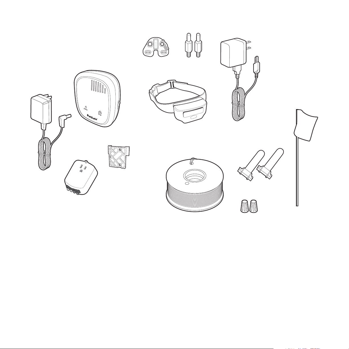
In the Box
Power
Adaptor
Fence Transmitter
Surge Protector
(USA & Canada Only)
Mounting
Bracket
Test Light
Tool
Contact Points
Receiver Collar with
Short Contact Points
Boundary Wire
Long
Receiver Charger
(USB Charging Cable
with Adaptor)
Gel-filled Capsules
Wire Connectors
(50)
Boundary Flags
Other Items You May Need
• Additional wire and flags (Part #PIG00-13769)
• Additional wire connectors and gel-filled splice capsules
• Drill and mounting hardware
• Tape measure
• Small Phillips screwdriver
• Pliers
• Staple gun
• Scissors
For help with setup and training, please visit petsafe.com.
+1 (800 ) 732-26776
• Lighter
• Shovel or lawn edger
• Wire stripping pliers
• Waterproofing compound (e.g. silicone caulk)
• PVC pipe or water hose
• Circular saw with masonry blade
• Non-metallic collar and leash
How the System Works
A radio signal travels from the fence transmitter through a buried wire, marking the boundaries you wish to set for your dog. Your dog wears
a receiver collar that detects the signal at the boundary. As your dog approaches the boundary, the receiver issues a warning tone. If he
proceeds further, he receives a safe but startling static correction. While harmless, the correction will persuade him to stay in the containment
area you have established. Boundary flags are a temporary visual aid for your pet; remove them after training. This PetSafe® Rechargeable
In-Ground Fence™ system has been proven safe, comfortable and effective for pets over 5 pounds.
Key Definitions
Fence Transmitter: Transmits the radio signal through the boundary wire.
Pet Area: The area within the warning zone where your pet can roam freely.
Warning Zone: The outer edge of the pet area where your pet’s receiver collar begins to
beep, warning him not to go into the static correction zone.
Static Correction Zone: The zone beyond the warning zone where your pet’s receiver collar
will emit a static correction, signaling him to return to the pet area.
Boundary Width: The combination of the warning zone and the static correction zone.
Surge Protector: Installed with the fence transmitter to protect it from lightning strikes and
power surges (USA and Canada only).
Receiver Collar: Receives the radio signal from the boundary wire.
Mode Button: Turns the receiver on/off and adjusts the level of static correction that your pet
receives outside the pet area.
Receiver Indicator Light: Indicates the level of correction at which the receiver collar is set.
This light also indicates battery status.
Contact Points: Delivers the safe static correction when your pet moves into the static
correction zone.
Receiver Charger: Charges the batteries inside the receiver collar.
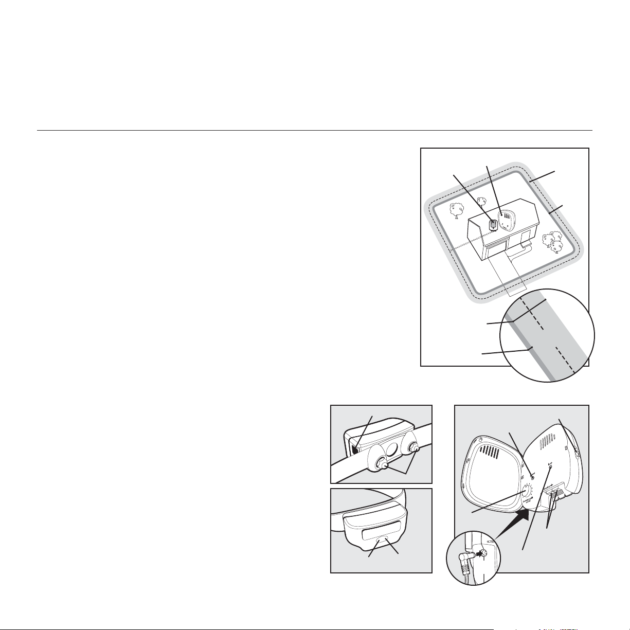
Receiver Charge Jack: The connection point for charging the
receiver battery.
Power Jack: Where the power adaptor plugs into the fence transmitter.
Boundary Control Switch: The switch located on the fence transmitter
to adjust according to the length of boundary wire used.
Boundary Wire Terminals: Where the boundary wires connect to the
fence transmitter in order to complete a continuous loop.
Loop Indicator Light: Indicates that the boundary wire makes a
complete loop, enabling the signal to be transmitted.
Boundary Width Control: Adjusts the width of the warning and static
correction zones.
Note: Adjusting the knob does not change the level of static correction
on the receiver collar.
Receiver Collar Fence Transmitter
Receiver Charge Jack
Contact Points
Mode Button
Receiver
Indicator
Light
Surge
Protector
with Power
Adapter
Fence
Transmitter
Static
Correction
Zone
Warning
Zone
Boundary Width
Control
Power
Jack
Pet
Area
Boundary
Boundary Control Switch
Power Light
Boundary Wire
Loop Indicator Light
Correction
Width
Terminals
Static
Zone
Warning
Zone
petsafe.com 7
Operating Guide
Step 1: Have Your Utilities Marked
1. Call your utility company to have your utility lines marked. If you
have neighbors using an in-ground pet containment system, you
will want to ask them where the boundary is located. Trust us, you
really do not want to skip this step.
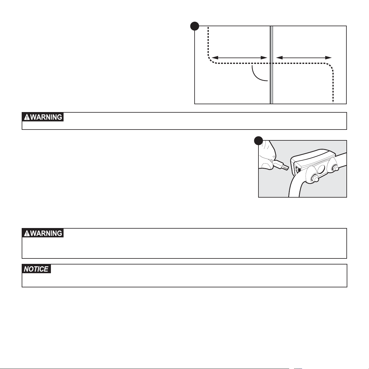
2. Make a plan for how you will work around any large metal
objects (like sheds) or wires. You can cross utility lines but only at
90° angles (1A).
Note: Large metal objects and wires can amplify and/or modulate
radio signals in unpredictable ways.
Underground cables can carry high voltage. Have all underground cables marked before you dig to bury your wire. In
most areas, this is a free service. Avoid these cables when you dig.
1A
Buried Cable
10’
90°
10’
Boundary Wire
Step 2: Charge the Receiver Collar
To charge the receiver collar, lift the rubber plug to allow access to the charge jack (2A). The
rubber plug needs to remain attached to the receiver collar. Plug one end of the charger into the
outlet and the other into the receiver collar. The jack and charger are keyed to fit one way. Do not
force it in backwards. The collar light is red while charging and green when fully charged. A built
in safety circuit prevents the receiver collar from overcharging. The first charge will take about 2 or 3
hours. Each charge can last up to 3 months depending on the frequency of use.
• The rechargeable Lithium Ion (Li-Ion) battery is not memory sensitive, does not require depletion
before charging, and cannot be over charged.
• The battery comes partially charged from the factory, but will require a full charge before first use.
• When storing the unit for long periods, remember to regularly give the battery a full charge. This should be done once every 3 to 4 months.
• This device contains a Lithium-Ion (Li-Ion) battery. Never incinerate, puncture, deform, short-circuit, or charge with an
inappropriate charger. Fire, explosion, property damage, or bodily harm may occur if this warning is not followed.
• The battery should be charged in areas with temperatures ranging from 32°F to 113°F / 0°C to 45°C. Recharging the
battery outside of this temperature range can cause the battery to overheat, explode or catch fire.
• You should expect hundreds of recharge cycles from your battery. However, do not charge your receiver collar every
night. Frequent charging can have a negative effect on the battery. We recommend that the receiver collar be used
until the receiver indicator light blinks red.
2A
Step 3: Install the Surge Protector and Transmitter
Lightning strikes that occur even several miles away from your installation can create power surges or spikes which may damage an
unprotected system. The surge protector is included to safeguard your Rechargeable In-Ground Fence™ system against surges or spikes that can
reach it via your AC power connection and/or boundary wire. Find a place to install the surge protector and transmitter. There are a few things
to consider when choosing an outlet for your surge protector and transmitter:
+1 (800 ) 732-26778
• We recommend using an outlet at least 30 ft. from the breaker box.
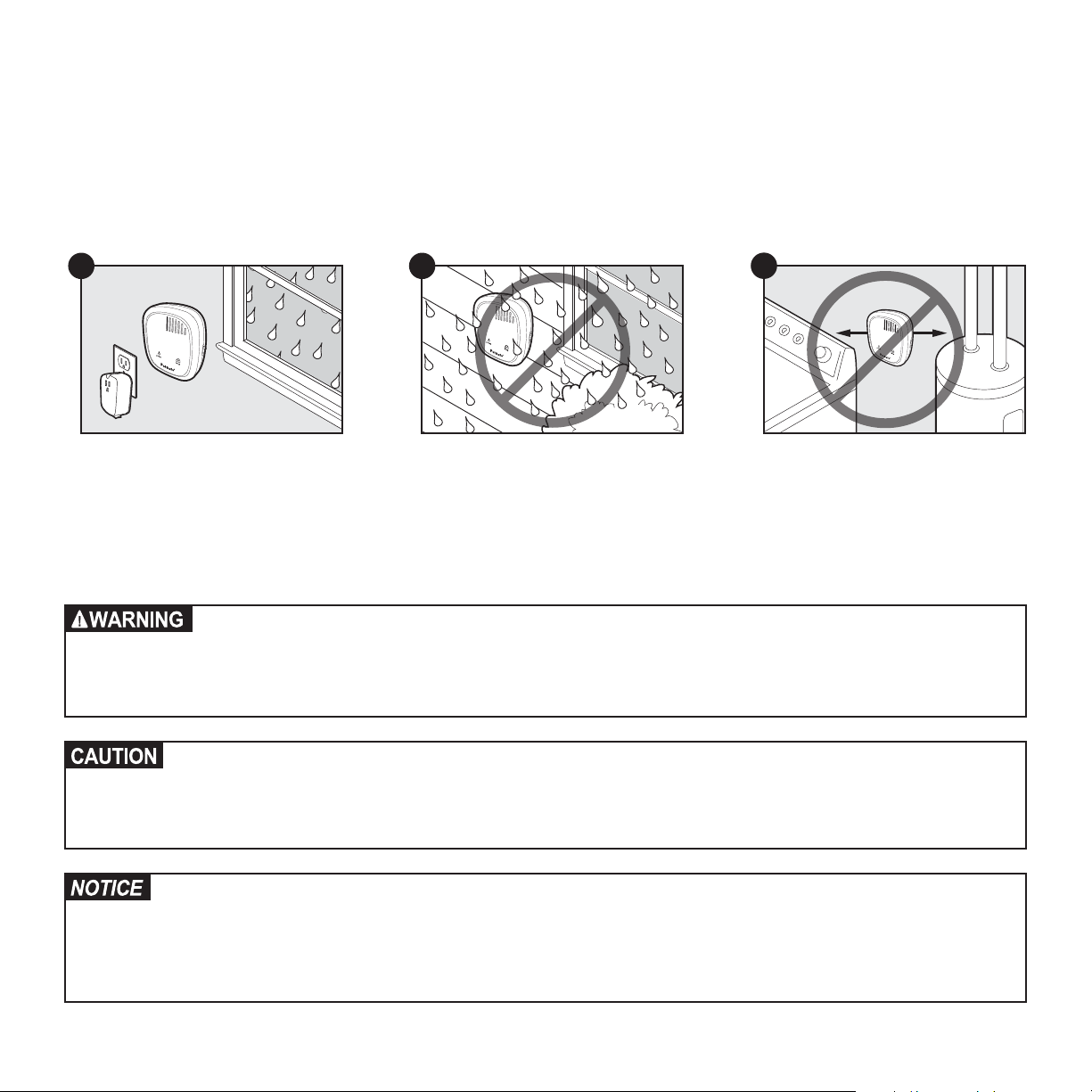
• Both the surge protector and transmitter should be indoors, in a dry, ventilated and protected area (3A, 3B).
• You will need to run wire from the transmitter to the boundary wire, so it must be near window or a wall that you can drill through (3A). The
wire should not be pinched or cross any utility lines.
• The temperatures in that location should not fall below -10°F / -23°C or rise above 104°F / 40°C.
• Both the surge protector and transmitter should be at least 3 ft. from large metal objects or appliances (3C). These items may interfere with
the signal consistency.
• In case your system sounds an alarm, place it where you will be able to hear and access it.
3A
3B
3C
3 ft.
3 ft.
To mount the fence transmitter, screw the mounting bracket onto a stationary surface such as a wall, and slide the fence transmitter onto the
bracket. Once you have mounted the fence transmitter, the boundary wire must exit the building. This can be accomplished via a window or
through a hole drilled through the wall. Ensure the drill path is clear of any utilities. Make sure the boundary wire is not cut off or pinched by a
window, door, or garage door, as this can damage it over time.
To prevent fires and electrical hazards, install the fence transmitter in buildings that are in accordance with state and local electrical codes.
• Do not install, connect or remove your system during a lightning storm. If the storm is close enough for you to hear
thunder, it is close enough to create hazardous surges.
• Risk of electric shock. Use the fence transmitter and surge protector indoors in dry location only.
• Turn off power to the outlet before you install or remove your surge protector.
• Risk of electric shock or fire. Use surge protector only with a duplex outlet with center screw.
• Do not install the surge protector if there is not at least 30 ft. (10 m) or more of wire between the electrical outlet
and electrical service panel.
• If possible, DO NOT use an AC circuit protected with a GFCI (ground fault circuit interrupter). Both the surge
protector and the fence system will function. However, in rare cases, nearby lightning may cause the GFCI to trip.
Without power, your pet may escape. You will have to reset the GFCI to restore power to the system.
• Plug the surge protector into a grounded (3-prong) outlet within 5 ft. of the fence transmitter. ALWAYS use a
grounded (3-prong) outlet to ensure protection.
• Do not remove the ground prong from the surge protector plug. Do not use a 3-prong plug to 2-prong outlet
converter. Doing so will make the surge protector ineffective against surges or spikes.
• For added protection, when unused for long periods of time or prior to thunderstorms, unplug from the wall outlet
and disconnect the loop boundary wires. This will prevent damage to the transmitter due to surges.
petsafe.com 9
Step 4: Design Your Boundary Zone
Basic Planning Tips
• Always design your layout, position the boundary wire and test the system as outlined in this guide before burying the boundary wire. You
do not want to find out after burying the wire that there is a problem with your layout or a loose connection somewhere.
• Sample layouts are provided in this section, and a grid for designing your layout is provided on the back of this guide.
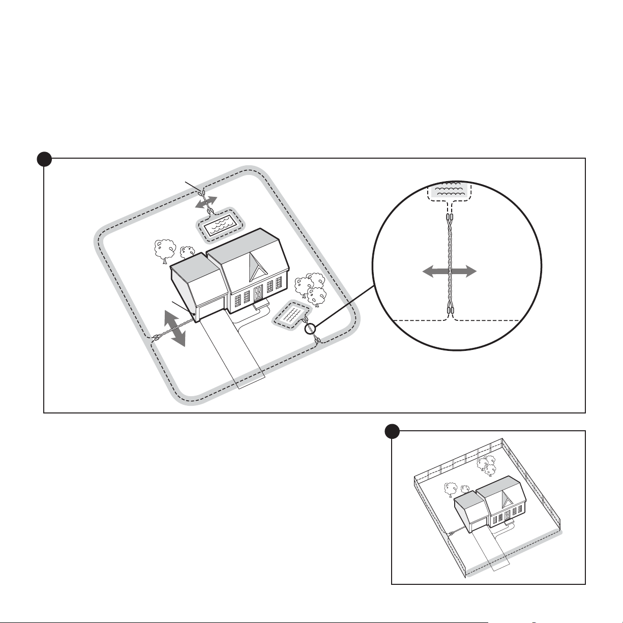
• The boundary wire must start at the fence transmitter and make a continuous loop back (4A).
• Always use gradual turns at the corners with a minimum of 3 ft. radius to produce a more consistent boundary (4B). Do not use sharp turns;
this will cause gaps in your boundary.
• Create areas in your yard that allow your pet to safely cross over the boundary wire without static correction by twisting the boundary wires
together 10 to 12 times per ft. (4C). This cancels the signal and allows your pet to safely cross over that area.
• To properly contain your pet, we recommend setting a boundary width for the warning and static correction zones to approximately
12–20 ft. (6 to 10 ft. on each side of the wire).
• Avoid making passageways too narrow for your pet to move about freely (e.g., along the sides of a house).
• The receiver collar can be activated inside the house if the boundary wire runs along the outside wall of the house. If this occurs,
remove your pet’s receiver collar before bringing him inside, decrease the range using the boundary width control knob or consider an
alternate layout.
4A
4B
+1 (800 ) 732-267710
Single or Double Loop Layout
The containment area can be created by using either a single boundary wire that is placed around the entire property (4C) or by doubling the
boundary wire along the same path (4E).
Single Loop Boundary
• To create a containment area for the entire property
• For exclusion areas around gardens, landscaping or pools
With a single loop layout, the boundary wire starts at the fence transmitter, advances out to the yard, continues all the way around the
perimeter of the property and connects back to the fence transmitter. This forms a boundary zone with a single wire.
4C
Wire
Splices
Place
Transmitter
Inside
Pets Can
Safely Cross
Twisted Wires
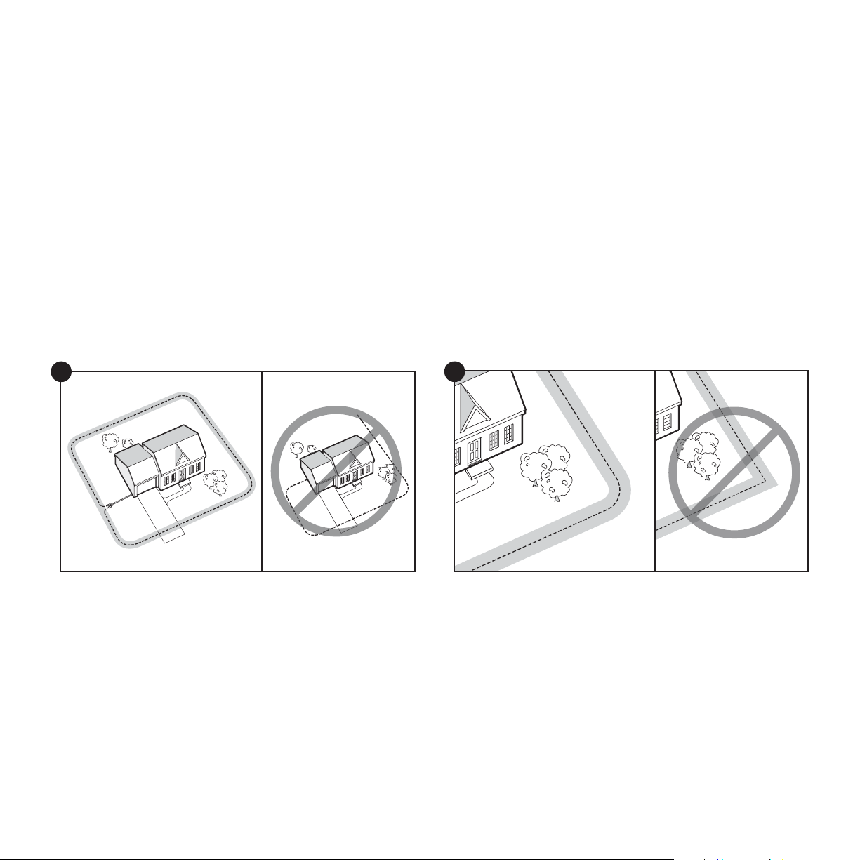
Sample 1: Perimeter Loop (4C) The perimeter loop is the most common layout. This
will allow your pet to freely and safely roam your entire property. It can also protect
gardens, pools and landscaping.
Sample 2: Full Perimeter Loop Using Existing Fence (4D) This layout allows you
to include your existing fence as part of your layout and keep your pet from jumping out
or digging under your existing fence. This layout also greatly reduces the installation time
since most of the wire will not need to be buried.
Run the wire from the fence transmitter to point A, then to point B and so on (B to C to D
to E) all the way around the entire property until back to point A again. The wires from
point A will then need to be twisted and connected back to the fence transmitter inside
your home.
10 Twists/ft.
Pets Can
Safely Cross
Twisted Wires
4D
C
B
D
A
E
petsafe.com 11
 Loading...